 Open Access Article
3D printing of anisotropic polymer nanocomposites with aligned BaTiO3 nanowires for enhanced energy density†
Hang
Luo
a,
Xuefan
Zhou
a,
Ru
Guo
a,
Xi
Yuan
*a,
Hehao
Chen
a,
Isaac
Abrahams
 b and
Dou
Zhang
 *a
*a
aState Key Laboratory of Powder Metallurgy, Central South University, Changsha, Hunan 410083, China. E-mail: dzhang@csu.edu.cn
bMaterials Research Institute, School of Biological Sciences, Queen Mary University of London, Mile End Road, London E1 4NS, UK
First published on 30th March 2020
Abstract
High power density capacitors possess broad application prospects in electric vehicles and power transmission systems. The development of capacitors with high energy density to realize miniaturization and lightweight application is the bottle-neck in this field. Strategies including orientated distribution of fillers have been utilized to increase the energy density of the dielectrics. In this work, we demonstrate high-performance flexible poly(vinylidene fluoride–chlorotrifluoroethylene) (P(VDF–CTFE)) nanocomposites with aligned BaTiO3 nanowires using 3D printing technology. The 3D printing process is computer-controlled, which can effectively achieve designed geometric shapes and precise size. The resulting BaTiO3 nanowires are highly aligned in a direction parallel to the surface of the nanocomposites due to the high shear environment within the very small 100 μm diameter nozzle. The highest energy density for these nanocomposites, with aligned BaTiO3 nanowires, was 14.52 J cm−3, which is 55% higher than that of nanocomposites with random BaTiO3 nanowires at the same loading level. This facile and readily scalable method of aligning one-dimensional fillers in a polymer matrix has potential not only in dielectric capacitor technology, but also in other fields where directional arrangement of low dimensional nanostructured materials is needed.
1 Introduction
High performance dielectric capacitors have been widely applied in electrical and electronic systems, such as electric vehicles, wind generators and aerospace power conditioning, due to their merits of super high power density and ability to withstand high operating voltage.1–7 The dielectric materials used in commercially available capacitors are mainly based on biaxially oriented polypropylenes (BOPP), which exhibit energy densities of only 1–1.2 J cm−3 at high applied electric field (∼640 kV mm−1).8 In this case, the low energy density of the dielectric becomes a limitation to their applications.9–11 Generally, the discharge energy density (Jdis) of a capacitor is determined by the eqn (1), | (1) |
 | (2) |
2 Experimental
2.1 Synthesis of BaTiO3 nanowires
The main materials used in the experiments are purchased from Sinopharm chemical reagent Co. Ltd., China, including titanium oxide powders (TiO2, anatase, 99.9% purity), sodium hydroxide (NaOH, 96% purity), Barium hydroxide octahydrate (Ba(OH)2·8H2O, 99.9% purity), hydrochloric acid solution (HCl, 37 wt%), and dimethylformamide solvent (DMF, 99.5% purity). The P(VDF–CTFE) powders with 15% CTFE are provided by PolyK Technologies, LLC, USA. All other chemicals were used “as received,” except for special notes. The BaTiO3 nanowires were synthesized by a hydrothermal method according to previous work.43 Firstly, 1.446 g of TiO2 was added to 70 ml NaOH solution (10 M) and the mixture was stirred for 2 h to form a homogeneous suspension. The hydrothermal reactions were carried out at 210 °C under an auto-generated pressure for 24 h in a 100 ml Teflon-lined autoclave. The Na2Ti3O7 products were washed using distilled water and then soaked in diluted 0.2 M HCl solution for 4 h to obtain hydrogen titanate nanowires (H2Ti3O7). Secondly, 0.150 g H2Ti3O7 were dispersed in 70 ml Ba(OH)2·8H2O solution (0.1 M) and the mixture was sonicated for 10 min. The hydrothermal reactions were carried out at 210 °C under auto-generated pressure for 24 h in a 100 ml Teflon-lined autoclave. The products were soaked in 0.2 M HCl solution briefly, then washed with distilled water several times and dried at 80 °C in an oven.2.2 Fabrication of BaTiO3/P(VDF–CTFE) dielectric nanocomposites
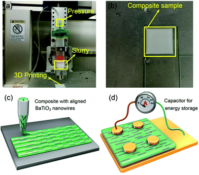
The anisotropic nanocomposites were fabricated using a deposition device based on a dispersing system (DR2203, EFD Inc., East Province, RI) according to our previous work.44 8 g of P(VDF–CTFE) was dissolved in 92 g dimethylformamide (DMF) and then was concentrated by evaporating the solvent to obtain high viscosity for printing. Samples with volume fractions of 2.5, 5.0 and 7.5% BaTiO3 nanowires relative to the P(VDF–CTFE) were prepared. Fig. 1a and b show optical photographs of the 3D printing equipment and a printed sample. The P(VDF–CTFE)/BaTiO3/DMF mixtures were stirred and ultrasonically treated to form a uniform slurry. The slurry was transferred to an extrusion syringe with a nozzle of 100 μm diameter and pressure of 10–20 psi. All of the samples were printed at room temperature on a three-axis CNC platform controlled by a computer regulator. The composites with randomly distributed BaTiO3 nanowires were prepared by a casting method. BaTiO3 nanowires were dispersed in 70![[thin space (1/6-em)]](https://www.rsc.org/images/entities/char_2009.gif) :
:![[thin space (1/6-em)]](https://www.rsc.org/images/entities/char_2009.gif) 30 (volume fraction) acetone/DMF hybrid solvent with sonication and stirring, and then mixed with P(VDF–CTFE) powder for further stirring and sonication for 48 h. The suspension was cast onto the surface of a clean glass, and dried at 80 °C for 12 h at vacuum. The capacitors were prepared by sputtering the Au electrode with a diameter of 2 mm using metal mask.
30 (volume fraction) acetone/DMF hybrid solvent with sonication and stirring, and then mixed with P(VDF–CTFE) powder for further stirring and sonication for 48 h. The suspension was cast onto the surface of a clean glass, and dried at 80 °C for 12 h at vacuum. The capacitors were prepared by sputtering the Au electrode with a diameter of 2 mm using metal mask.
2.3 Characterization
The crystalline phases of BaTiO3 nanowires were evaluated by X-ray powder diffraction (XRD, Rigaku D/max 2550, Japan) with Cu-Kα radiation (λ = 1.5418 Å) at room temperature. The morphology of the BaTiO3 nanowires and nanocomposite films were observed using a scanning electron microscope (SEM, Nova NanoSEM230, USA). High-resolution transmission electron microscopy (HR-TEM) images of the BaTiO3 nanowires were taken with a Titan G2 60-300, using an accelerating voltage of 300 kV. The morphology and orientation of the nanowire composites were examined using polarizing microscopy (POM, Leica DM-LM-P). The rheological properties of the BaTiO3/P(VDF–CTFE) slurry were studied using a rotational rheometer (AR2000 EX, TA Instruments, New Castle, DE) with a parallel plate diameter of 40 mm. The frequency dependent permittivity and dielectric loss of the nanocomposite films were measured using an Agilent 4294A LCR meter with frequency ranging from 100 Hz to 10 MHz. The electric displacement–electric field (D–E) loops was measured using a TF analyzer 2000 ferroelectric polarization tester (aixACT, Germany) and Delta 9023 furnace in a silicone oil bath at room temperature and 10 Hz.3 Results and discussion
Fig. 1c and d show sketches of anisotropic nanocomposites with aligned BaTiO3 nanowires induced by shear stress along the printing direction. During the extrusion process, the BaTiO3 nanowires suffer from a high shear environment along the inner wall of the 100 μm diameter nozzle, which forces the BaTiO3 nanowires to align parallel to the direction of printing.BaTiO3 nanowires were selected as the fillers due to the advantages of high permittivity and low dielectric loss.45–48 Firstly, high aspect ratio Na2Ti3O7 nanowires with smooth surface were prepared, of which the morphologies and crystal structure were confirmed as shown in Fig. S1a and b (ESI†). Then, the Na2Ti3O7 nanowires were converted into H2Ti3O7 and finally to BaTiO3 nanowires in the second step of the hydrothermal reaction. It is clear that the BaTiO3 nanowires possess super-high aspect ratios and uniform morphology, as shown in Fig. 2a and Fig. S1c (ESI†). Fig. S1d (ESI†) shows the XRD pattern of BaTiO3 nanowires, which can be attributed to the tetragonal phase of BaTiO3 (PDF: 31-0174). Fig. 2b shows a high resolution transmission electron microscrograph of a single BaTiO3 nanowire. Parallel lattice spacing of approximately 0.36 nm and 0.20 nm, corresponding to the (1![[3 with combining macron]](https://www.rsc.org/images/entities/char_0033_0304.gif) 1) and (002) planes of the tetragonal phase, respectively were identified. The distribution of BaTiO3 nanowire fillers in the nanocomposites is seen in the SEM and POM images shown Fig. 1c and d, respectively. It is clear that the BaTiO3 nanowires are well dispersed and aligned in one direction in the nanocomposite. For comparison, the SEM and POM images of the nanocomposites with randomly distributed BaTiO3 nanowires prepared by the casting method are shown Fig. S2e, f and S3b (ESI†).
1) and (002) planes of the tetragonal phase, respectively were identified. The distribution of BaTiO3 nanowire fillers in the nanocomposites is seen in the SEM and POM images shown Fig. 1c and d, respectively. It is clear that the BaTiO3 nanowires are well dispersed and aligned in one direction in the nanocomposite. For comparison, the SEM and POM images of the nanocomposites with randomly distributed BaTiO3 nanowires prepared by the casting method are shown Fig. S2e, f and S3b (ESI†).
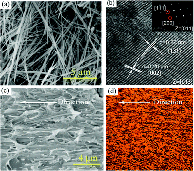 | ||
| Fig. 2 (a) SEM image of BaTiO3 nanowires; (b) HRTEM image of a single BaTiO3 nanowire; (c) SEM and (d) POM images of nanocomposites prepared by 3D printing with 5 vol% aligned BaTiO3 nanowires. | ||
Fig. 3a shows the relationship between shear rate and viscosity in P(VDF–CTFE) slurries with different volume fractions of BaTiO3 nanowires. The slurries show shear thinning characteristics at low shear rate, and when the shear rate increases to around 100 s−1, the viscosity of slurries is close to a constant value. At the shear rate of 100 s−1, the viscosity of the three samples is about 6.7 mPa s, which means that the change of filler loadings over a very small range shows little effect on the viscosity of the slurry. Fig. 3b shows the shear rate dependent shear stress of slurries with different BaTiO3 nanowires loadings. The slope of the curves represents the viscosity of the suspension. At a constant shear rate, the slurries shows similar viscosity, which is consistent with the results shown in Fig. 3a. Slurries with shear thinning behavior meet the rheological requirements for application in 3D direct writing. At low shear rate, the slurries shows high viscosity, which allow them to avoid agglomeration and settling of the BaTiO3 nanowires within the printing needle tube. At high shear rate, the slurries show low viscosity, which allows them to have sufficient fluidity to be extruded from the printing needle.49,50
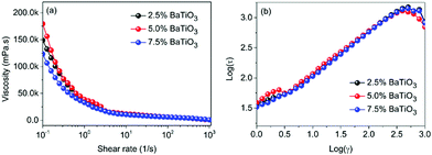 | ||
| Fig. 3 (a) Shear rate dependence of viscosity and (b) logarithmic plot of shear stress of the slurries with various BaTiO3 loadings. | ||
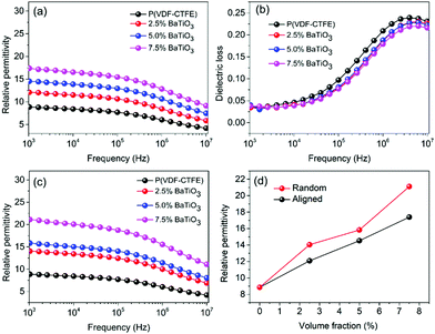
Nanocomposites with different BaTiO3 nanowire loadings were prepared by the 3D direct writing method and compared with those made using a traditional solution casting method. The permittivity and dielectric loss of the prepared nanocomposites are summarized in Fig. 4. Fig. 4a and c show the frequency dependent permittivity of BaTiO3 nanowire/P(VDF–CTFE) nanocomposites, where the BaTiO3 nanowires are aligned perpendicular to electric field direction (Fig. 4a) compared to the random distribution (Fig. 4c). The permittivity of the nanocomposites with aligned BaTiO3 nanowires is smaller than that of nanocomposites with random BaTiO3 nanowires. For example, when the loadings of random BaTiO3 nanowires is 2.5, 5.0 and 7.5 vol%, the permittivity of the nanocomposites with random BaTiO3 nanowires is 14, 15.5 and 21.5, respectively, while the permittivity of the nanocomposites with aligned BaTiO3 nanowires is 12, 14 and 17.5, respectively (Fig. 4d).
The total permittivity over the high and low frequency ranges ε′ is the sum of interfacial and space charge contributions (eqn (3)):
| ε′ = εMWS′ + εDIP′ | (3) |
 | (4) |
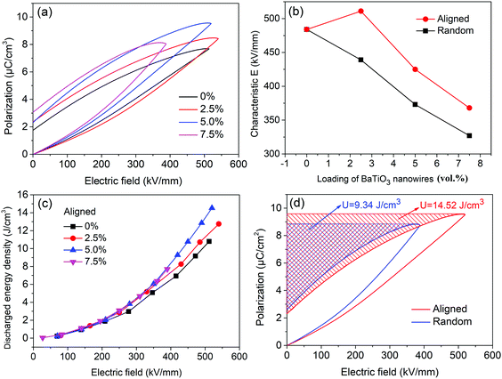
Fig. 5a shows typical P–E loops for P(VDF–CTFE) nanocomposites with aligned BaTiO3 nanowires, from which the saturation polarization and residual polarization can be obtained and the energy density can be calculated. Due to the high permittivity of BaTiO3 fillers and the introduction of interfacial polarization, the saturation polarization increases with increasing BaTiO3 loading. When the loading of aligned BaTiO3 nanowires is 2.5 vol%, the nanocomposites achieve higher polarization and breakdown strength (Fig. S4, ESI†) than that in P(VDF–CTFE). This means that nanocomposites with low loadings of aligned BaTiO3 nanowires can simultaneous improve permittivity and breakdown strength. Fig. 5b shows the characteristic breakdown strengths of nanocomposites with aligned and random BaTiO3 nanowires at various loading. The nanocomposite with aligned BaTiO3 nanowires possesses higher breakdown strength than the nanocomposite with random BaTiO3 nanowires at the same loading level. The discharged energy density of the nanocomposites with aligned BaTiO3 nanowires as a function of applied electric field is shown in Fig. 5c. The discharged energy density of all composites is similar at low field, but at high field increases with increasing loading level. The maximum energy density achieved in nanocomposites with aligned BaTiO3 nanowires was 14.52 J cm−3 for the sample with 5.0 vol% loading, which is 55% higher than that of the nanocomposite with randomly aligned BaTiO3 nanowires at the same loading level. The energy density is directly determined by two factors including the relatively permittivity (polarization) and breakdown strength of the composite according to eqn (2). Incorporated BaTiO3 fillers into the polymer matrix, the permittivity (polarization) of the composite will be increased and which will continue to increase with the loading of BaTiO3 fillers due to the high permittivity of the BaTiO3 itself. However, high loading of BaTiO3 filler will introduce inevitable defects, in addition, the mismatch between the filler and matrix will lead to the concentration of electric field distribution, both of which will decrease the breakdown strength of the composites. It means that the permittivity and breakdown strength are two contradictory factors. The results showed that the composite with 5.0 vol% BaTiO3 nanowires get the balance point, which simultaneously achieved high polarization and breakdown strength.51,52
4 Conclusions
It has been shown that 3D printing is an effective method to prepare aligned BaTiO3 nanowires/P(VDF–CTFE) nanocomposites. P(VDF–CTFE) nanocomposites with aligned BaTiO3 nanowires possess higher breakdown strength and energy density compared to those with randomly distributed BaTiO3 nanowires, with a maximum discharged energy density of 14.52 J cm−3 achieved with 5.0 vol% nanowire loading, 55.5% higher than that of nanocomposites with randomly distributed nanowires at the same loading level. This work provides a facile route to align one dimensional inorganic fillers in a polymer matrix that is readily scalable to prepare high performance dielectrics for capacitors.Conflicts of interest
There are no conflicts to declare.Acknowledgements
The authors would like to acknowledge funding from National Natural Science Foundation of China (51672311), Hunan Natural Science Foundation (2019JJ40349), and State Key Laboratory of Powder Metallurgy, Central South University, Changsha, China.Notes and references
- N. Meng, X. Ren, G. Santagiuliana, L. Ventura, H. Zhang, J. Wu, H. Yan, M. J. Reece and E. Bilotti, Nat. Commun., 2019, 10, 4535 CrossRef PubMed.
- R. Guo, J. I. Roscow, C. R. Bowen, H. Luo, Y. Huang, Y. Ma, K. Zhou and D. Zhang, J. Mater. Chem. A, 2020, 8, 3135–3144 RSC.
- X. Huang, B. Sun, Y. Zhu, S. Li and P. Jiang, Prog. Mater. Sci., 2019, 100, 187–225 CrossRef CAS.
- Y. Zhu, Y. Zhu, X. Huang, J. Chen, Q. Li, J. He and P. Jiang, Adv. Energy Mater., 2019, 9, 1901826 CrossRef.
- Q. Li, L. Chen, M. R. Gadinski, S. Zhang, G. Zhang, H. Li, A. Haque, L.-Q. Chen, T. N. Jackson and Q. Wang, Nature, 2015, 523, 576–579 CrossRef CAS PubMed.
- X. Zhang, B.-W. Li, L. Dong, H. Liu, W. Chen, Y. Shen and C.-W. Nan, Adv. Mater. Interfaces, 2018, 5, 1800096 CrossRef.
- Z. Pan, L. Yao, J. Zhai, X. Yao and H. Chen, Adv. Mater., 2018, 30, 1705662 CrossRef PubMed.
- H. Luo, X. Zhou, C. Ellingford, Y. Zhang, S. Chen, K. Zhou, D. Zhang, C. R. Bowen and C. Wan, Chem. Soc. Rev., 2019, 48, 4424–4465 RSC.
- A. Mannodi-Kanakkithodi, G. M. Treich, T. D. Huan, R. Ma, M. Tefferi, Y. Cao, G. A. Sotzing and R. Ramprasad, Adv. Mater., 2016, 28, 6277–6291 CrossRef CAS PubMed.
- Z. M. Dang, J. K. Yuan, S. H. Yao and R. J. Liao, Adv. Mater., 2013, 25, 6334–6365 CrossRef CAS PubMed.
- Z.-M. Dang, M.-S. Zheng and J.-W. Zha, Small, 2016, 12, 1688–1701 CrossRef CAS PubMed.
- G. Wang, X. Huang and P. Jiang, ACS Appl. Mater. Interfaces, 2015, 7, 18017–18027 CrossRef CAS PubMed.
- Y. Wang, L. Wang, Q. Yuan, J. Chen, Y. Niu, X. Xu, Y. Cheng, B. Yao, Q. Wang and H. Wang, Nano Energy, 2018, 44, 364–370 CrossRef CAS.
- N. L. Meereboer, I. Terzic, G. Portale and K. Loos, Nano Energy, 2019, 64, 103939 CrossRef.
- Y. Wang, L. Wang, Q. Yuan, Y. Niu, J. Chen, Q. Wang and H. Wang, J. Mater. Chem. A, 2017, 5, 10849–10855 RSC.
- K. Bi, M. Bi, Y. Hao, W. Luo, Z. Cai, X. Wang and Y. Huang, Nano Energy, 2018, 51, 513–523 CrossRef CAS.
- Z. Yao, Z. Song, H. Hao, Z. Yu, M. Cao, S. Zhang, M. T. Lanagan and H. Liu, Adv. Mater., 2017, 29, 1601727 CrossRef PubMed.
- H. Tang, Y. Lin and H. A. Sodano, Adv. Energy Mater., 2013, 3, 451–456 CrossRef CAS.
- P. Kim, N. M. Doss, J. P. Tillotson, P. J. Hotchkiss, M.-J. Pan, S. R. Marder, J. Li, J. P. Calame and J. W. Perry, ACS Nano, 2009, 3, 2581–2592 CrossRef CAS PubMed.
- H. Tang and H. A. Sodano, Nano Lett., 2013, 13, 1373–1379 CrossRef CAS PubMed.
- H. Tang, Y. Lin and H. A. Sodano, Adv. Energy Mater., 2012, 2, 469–476 CrossRef CAS.
- D. Zhang, C. Ma, X. Zhou, S. Chen, H. Luo, C. R. Bowen and K. Zhou, J. Phys. Chem. C, 2017, 121, 20075–20083 CrossRef CAS.
- D. Zhang, X. Zhou, J. Roscow, K. Zhou, L. Wang, H. Luo and C. R. Bowen, Sci. Rep., 2017, 7, 45179 CrossRef CAS PubMed.
- H. Luo, S. Chen, L. Liu, X. Zhou, C. Ma, W. Liu and D. Zhang, ACS Sustainable Chem. Eng., 2019, 7, 3145–3153 CrossRef CAS.
- H. Luo, J. Roscow, X. Zhou, S. Chen, X. Han, K. Zhou, D. Zhang and C. R. Bowen, J. Mater. Chem. A, 2017, 5, 7091–7102 RSC.
- D. Zhang, W. Liu, R. Guo, K. Zhou and H. Luo, Adv. Sci., 2018, 5, 1700512 CrossRef PubMed.
- D. Zhang, W. Liu, L. Tang, K. Zhou and H. Luo, Appl. Phys. Lett., 2017, 110, 133902 CrossRef.
- H. Luo, C. Ma, X. Zhou, S. Chen and D. Zhang, Macromolecules, 2017, 50, 5132–5137 CrossRef CAS.
- J. Li, P. Khanchaitit, K. Han and Q. Wang, Chem. Mater., 2010, 22, 5350–5357 CrossRef CAS.
- T. Kim, R. Trangkanukulkij and W. S. Kim, Sci. Rep., 2018, 8, 3805 CrossRef PubMed.
- N. Hu, Y. Karube, C. Yan, Z. Masuda and H. Fukunaga, Acta Mater., 2008, 56, 2929–2936 CrossRef CAS.
- S.-L. Zhong, L.-J. Yin, J.-Y. Pei, X.-Y. Li, S.-J. Wang and Z.-M. Dang, Appl. Phys. Lett., 2018, 113, 122904 CrossRef.
- C. Andrews, Y. Lin and H. A. Sodano, Smart Mater. Struct., 2010, 19, 025018 CrossRef.
- B. Xie, H. Zhang, Q. Zhang, J. Zang, C. Yang, Q. Wang, M.-Y. Li and S. Jiang, J. Mater. Chem. A, 2017, 5, 6070–6078 RSC.
- X. Zhang, J. Jiang, Z. Shen, Z. Dan, M. Li, Y. Lin, C.-W. Nan, L. Chen and Y. Shen, Adv. Mater., 2018, 30, 1707269 CrossRef PubMed.
- D. He, Y. Wang, S. Song, S. Liu and Y. Deng, ACS Appl. Mater. Interfaces, 2017, 9, 44839–44846 CrossRef CAS PubMed.
- M. Gao, L. Li, W. Li, H. Zhou and Y. Song, Adv. Sci., 2016, 3, 1600120 CrossRef PubMed.
- J. H. Kim, S. Lee, M. Wajahat, H. Jeong, W. S. Chang, H. J. Jeong, J. R. Yang, J. T. Kim and S. K. Seol, ACS Nano, 2016, 10, 8879 CrossRef CAS PubMed.
- B. G. Compton and J. A. Lewis, Adv. Mater., 2015, 26, 5930–5935 CrossRef PubMed.
- D. E. Yunus, W. Shi, S. Sohrabi and Y. Liu, Nanotechnology, 2016, 27, 495302 CrossRef PubMed.
- N. Phatharapeetranun, B. Ksapabutr, D. Marani, J. R. Bowen and V. Esposito, J. Mater. Chem. C, 2017, 5, 12430–12440 RSC.
- K. Kanguk, Z. Wei, Q. Xin, A. Chase, W. R. Mccall, C. Shaochen and D. J. Sirbuly, ACS Nano, 2014, 8, 9799 CrossRef PubMed.
- B. Xie, Q. Zhang, H. Zhang, G. Zhang, S. Qiu and S. Jiang, Ceram. Int., 2016, 42, 19012–19018 CrossRef CAS.
- J. Liao, H. Chen, L. Hang, X. Wang, K. Zhou and Z. Dou, J. Mater. Chem. C, 2017, 5, 5867–5871 RSC.
- B. Jiang, J. Iocozzia, L. Zhao, H. Zhang, Y.-W. Harn, Y. Chen and Z. Lin, Chem. Soc. Rev., 2019, 48, 1194–1228 RSC.
- W. Xu, G. Yang, L. Jin, J. Liu, Y. Zhang, Z. Zhang and Z. Jiang, ACS Appl. Mater. Interfaces, 2018, 10, 11233–11241 CrossRef CAS PubMed.
- P. Hu, S. Gao, Y. Zhang, L. Zhang and C. Wang, Compos. Sci. Technol., 2018, 156, 109–116 CrossRef CAS.
- Y. N. Hao, X. H. Wang, S. O'Brien, J. Lombardi and L. T. Li, J. Mater. Chem. C, 2015, 3, 9740–9747 RSC.
- N. Phatharapeetranun, B. Ksapabutr, D. Marani, J. R. Bowen and V. Esposito, J. Mater. Chem. C, 2017, 5, 12430–12440 RSC.
- M. Gao, L. Li, W. Li, H. Zhou and Y. Song, Adv. Sci., 2016, 3, 1600120 CrossRef PubMed.
- Y. P. Ma, H. Luo, X. F. Zhou, R. Guo, F. Dang, K. C. Zhou and D. Zhang, Nanoscale, 2020 10.1039/C9NR08572F.
- H. Luo, D. Zhang, C. Jiang, X. Yuan, C. Chen and K. Zhou, ACS Appl. Mater. Interfaces, 2015, 7, 8061–8069 CrossRef CAS PubMed.
Footnote |
| † Electronic supplementary information (ESI) available. See DOI: 10.1039/d0ma00045k |
| This journal is © The Royal Society of Chemistry 2020 |

