
 Open Access Article
 This Open Access Article is licensed under a Creative Commons Attribution-Non Commercial 3.0 Unported Licence
Alkoxy-functionalized ionic liquid electrolytes: understanding ionic coordination of calcium ion speciation for the rational design of calcium electrolytes†
Xinpei
Gao
 ab,
Xu
Liu
ab,
Alessandro
Mariani
ab,
Giuseppe Antonio
Elia
ab,
Manuel
Lechner
c,
Carsten
Streb
c and
Stefano
Passerini
*ab
ab,
Xu
Liu
ab,
Alessandro
Mariani
ab,
Giuseppe Antonio
Elia
ab,
Manuel
Lechner
c,
Carsten
Streb
c and
Stefano
Passerini
*ab
aHelmholtz Institute Ulm (HIU), Helmholtzstrasse 11, 89081 Ulm, Germany
bKarlsruhe Institute of Technology (KIT), P.O. Box 3640, 76021 Karlsruhe, Germany. E-mail: stefano.passerini@kit.edu
cInstitute of Inorganic Chemistry I, Ulm University, Albert-Einstein-Allee 11, 89081 Ulm, Germany
First published on 9th July 2020
Abstract
There is growing interest in the rational design of electrolytes for multivalent-ion batteries by tuning the molecular-level interactions of solvate species present in the electrolytes. Herein, we report our effort to control Ca-ion speciation in ionic liquid (IL) based electrolytes through the design of alkoxy-functionalized cations. Quantitative analysis reveals that the alkoxy-functionalized ammonium cation (N07+), bearing seven ether oxygen atoms, can effectively displace the bis(trifluoromethanesulfonyl)imide anion (TFSI−) from the Ca2+ ion coordination sphere, facilitating the reversible Ca deposition/stripping process. More importantly, post-analysis of Ca deposits surface chemistry and density functional theory calculations of Ca-ion speciation indicate the formation of an organic-rich, but inorganic-poor solid electrolyte interphase layer, which enables Ca2+ ion diffusion rather than passivating the Ca metal electrode. Finally, as a proof-of-concept, a prototype Ca/V2O5 cell using the optimized IL-based electrolyte ([Ca(BH4)2]0.05[N07TFSI]0.95) is demonstrated for the first time, exhibiting a remarkable initial discharge capacity of 332 mA h g−1 and reversible capacity of 244 mA h g−1.
Broader contextThe present lithium-ion batteries will continue to dominate the market and research efforts as the most promising electrochemical energy storage system. However, aside from controversial debates on cobalt and lithium supply, the rapidly growing global energy storage demand is leading research efforts toward new sustainable battery chemistries based on abundant elements. From the viewpoint of element strategy, multivalent-ion batteries based on magnesium and calcium have attracted substantial interest as potential post-lithium ion energy storage devices. The problem generally encountered with multivalent metal anodes is the limited development of suitable electrolytes. Accordingly, there is a growing interest in the rational design of electrolytes for multivalent-ion batteries by tuning the molecular-level interactions of solvate species present in the electrolytes. Herein, we report our effort to control Ca-ion speciation in ionic liquid-based electrolytes, which may provide guidance for future multivalent electrolytes. |
Introduction
The prevailing lithium-ion battery (LIB) technology will continue to dominate the market and research efforts for a fairly long period of time. However, the large-scale application of LIBs is raising critical concerns about the limited and unevenly distributed raw materials such as cobalt, nickel, and lithium, which are essential elements in current LIB technologies.1 Furthermore, substitution of metal-ion for metal-anode battery chemistries is enthusiastically pursued, as it can substantially enhance the energy density of the battery systems.2 If more abundant, eco-friendly, and non-toxic metals could be used, the overall battery technologies would also benefit from cost and sustainability.3 Thus, there is a re-emerged interest in multivalent-ion batteries (MIBs) such as those based on magnesium,4 calcium,5 and aluminum6 as potential energy storage devices beyond LIBs. Among the multivalent electropositive metals, most research efforts have focused on magnesium-based chemistries.7,8 However, in comparison with the extensively studied magnesium, calcium offers higher abundance (the third most abundant metal element in the Earth's crust), lower reduction potential (−2.87 V for Ca vs. −2.38 V for Mg, based on SHE), and expected faster reaction kinetics owing to the lower ion charge density.5 Hence, rechargeable calcium batteries promise higher cell voltage and better power performance than rechargeable magnesium batteries.It is now well accepted that the solid electrolyte interphase (SEI) model proposed by Peled in 1979 is essential for the successful operation of non-aqueous, alkali-metal batteries such as lithium and sodium systems.9 This model concludes that the degradation products of salts, solvents, and impurities, form a protective solid passivation layer adhering to the metal electrode surface. This SEI layer is ion conductive and electron insulating, facilitating the metal anode dissolution/deposition processes while preventing further parasitic reductions of the electrolyte components.10 However, like for other alkaline-earth metals, one of the most serious hurdles associated with the use of the calcium anode arises from the unsuitable SEI layer, which blocks calcium diffusion and disables plating and stripping processes.11 In fact, while the typical SEI layer of alkali-metal anodes consists of inorganic compounds like LiF and LiO2 that are cationic conductors, that of alkaline-earth metal anodes consist of fluorides and oxides, which are anionic conductors.9,12 Inspired by the success of magnesium batteries using Grignard reagents as electrolytes, a first attempt to develop rechargeable calcium batteries might be based on the analogous calcium-based Grignards, which is probably an SEI-free system.13 However, hindered by the instabilities of organocalcium reagents, no reports have been made of similar calcium electrolytes.14 Thus, a viable electrolyte forming a Ca2+ ion conductive SEI on the metal anode is strongly desirable for the development of rechargeable calcium batteries.
Although it has been found that CaF2 is not a good SEI compound because of its extremely low cation diffusivity, two independent studies have indeed demonstrated successful calcium plating and stripping in the presence of CaF2 as the major component of the SEI layer.15,16 The pioneering work from Ponrouch et al. proved reversible plating/stripping of calcium metal using Ca(BF4)2/ethylene carbonate/propylene carbonate electrolyte at elevated temperature.15 Recently, successful calcium plating and stripping at room temperature was also reported using calcium fluorinated alkoxyborate salt dissolved in Dimethoxy ethane.16,17 In both cases, the formation of CaF2 can derive from salt decomposition; thus it is most likely present in the SEI layer. Compared with CaF2, CaH2 might be a better candidate for Ca2+ ion conductive SEI layer. In fact, it has been found that in the Ca(BH4)2/tetrahydrofuran electrolyte, the SEI layer is composed entirely of CaH2, granting 95% coulombic efficiency of calcium plating and stripping.18–20 However, CaH2 is highly reactive, and the formation of CaH2 passivation layer requires additional electrochemical purification of the electrolyte and a rather clean glovebox atmosphere.
Instead of a predominantly inorganic SEI, a polymeric SEI layer based on the rational design of electrolyte components might be a more attractive strategy to achieve reversible calcium plating and stripping.21 In order to demonstrate this, we focused on the use of ionic liquid (IL)-based electrolytes. ILs have been widely studied as electrolyte components for LIBs and MIBs benefitting from their negligible volatility as well as high thermal and electrochemical stability.22 Moreover, ILs are prepared by coupling charge delocalized organic or inorganic ions, thus their physicochemical properties can be easily tailored to a specific application by changing the structure of the component ions.23 ILs do provide ideal model systems to control speciation of metal ions and ionic interaction in the electrolyte, which are crucial for understanding the electrolyte activity and SEI formation process.
Herein, we report our effort to control Ca-ion speciation in IL-based electrolytes through the design of alkoxy-functionalized cations. Quantitative analysis revealed that the polyether chains could effectively displace TFSI− anion from the Ca2+ ion coordination sphere, which facilitates the reversible Ca deposition/stripping process. More importantly, post-analysis of Ca deposits surface chemistry and density functional theory calculation of Ca-ion speciation indicate the formation of an organic-rich, but inorganic-poor SEI layer, which enables Ca2+ ion diffusion rather than passivates the Ca metal. Finally, as a proof-of-concept, a prototype Ca/V2O5 cell using the IL-based electrolyte ([Ca(BH4)2]0.05[N07TFSI]0.95) is demonstrated for the first time, exhibiting a remarkable initial discharge capacity of 332 mA h g−1 and reversible capacity of 244 mA h g−1.
Results and discussion
Compared with the lithium and magnesium analogues, calcium salts have a significantly lower solubility in TFSI-based ILs. The solubility of calcium bis(trifluoromethanesulfonyl)imide (Ca(TFSI)2) in Pyr14TFSI is only around 3 mol%, while that of LiTFSI and Mg(TFSI)2 are all above 30 mol%.24,25 This is because the Ca2+ ion exhibits a larger radius (1.00 Å) as compared to Mg2+ ion (0.72 Å) and Li+ ion (0.76 Å), which results in larger preferred coordination numbers.26 Differential Scanning Calorimetry (DSC) was used to determine the phase behavior of different IL electrolytes (chemical structures of the ILs are given in Scheme S1 in ESI†) and the corresponding thermograms are shown in Fig. 1. In the heating trace of neat Pyr14TFSI, a glass transition (Tg) was detected followed by a crystallization peak (Tc) and a melting peak (Tm), which behaves as a typical supercooled liquid.24 With the addition of Ca(TFSI)2, the Tc shifts to lower temperature while the Tm shifts to a higher temperature, indicating a more pronounced freezing phenomenon. In addition, a new crystallization peak (Tc′) is observed, which can be attributed to the crystalline phase [Pyr14]2[Ca(TFSI)4].27 The introduction of alkoxy group in the IL's cation structure is known to lower the lattice energy and reduce/suppress the crystallization of neat ILs as well as IL-based solutions.28 Indeed, the crystallization of the Pyr1201TFSI electrolytes is effectively suppressed while the solubility of Ca(TFSI)2 is slightly increased to 5 mol%. In the thermograms of Pyr1201TFSI with and without Ca-salt (Fig. 1b), the Tc and Tm peaks completely disappear. The IL and its mixture with the Ca-salt behave as glass-forming liquids with low glass transition temperatures. It is worth noting that replacing the pyrrolidinium cation with an ammonium cation, e.g., N01TFSI and N07TFSI, further increases the solubility of Ca(TFSI)2 to about 15 mol%. The N01TFSI-based electrolytes exhibit a similar glass-forming behavior as the Pyr1201TFSI-based ones (Fig. 1c). In the thermogram of neat N01TFSI, the only phase transition detected is Tg, which value increases with increasing Ca-salt contents. In the heating trace of [Ca(TFSI)2]0.1[N01TFSI]0.9, a new pair of Tc and Tm peaks is observed, which indicates a faint freezing phenomenon. Interestingly, the thermal behavior of the [Ca(TFSI)2]x[N07TFSI]1−x electrolytes (Fig. 1d) is quite different than those of Pyr14TFSI-, Pyr1201TFSI-, and N01TFSI-based electrolytes. In these latter cases, in fact, increasing the Ca-salt content facilitates the solidification (freezing) of the IL solution, which suggests that the ionic interactions between the Ca2+ ion and the ionic liquids (most likely with the TFSI− anion) promote crystallization.24 On the contrary, the increasing Ca-salt content inhibits the crystallization of the [Ca(TFSI)2]x[N07TFSI]1−x electrolytes. As shown in Fig. 1d, the Tc and Tm peaks gradually diminished with the increasing of Ca(TFSI)2 molar fraction, indicating that the interactions between the Ca2+ ion and the N07TFSI lead to the formation of different Ca2+–IL complexes, which crystallization is inhibited.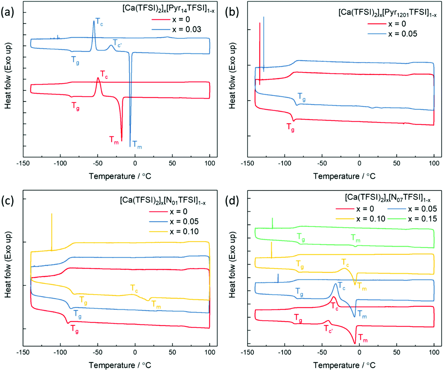 | ||
| Fig. 1 DSC thermograms of [Ca(TFSI)2]x[Pyr14TFSI]1−x (a), [Ca(TFSI)2]x[Pyr1201TFSI]1−x (b), [Ca(TFSI)2]x[N01TFSI]1−x (c), and [Ca(TFSI)2]x[N07TFSI]1−x (d). Scan rate: 5 °C min−1. The traces are vertically shifted for clarity; all tick marks on the left axis correspond to heat flow differences of 0.25 W g−1. | ||
Concurrent with the limited research on Ca electrolytes, information about the solvation structure of Ca-ion speciation is seldom reported in the literature.29 Herein, Raman spectroscopy was employed to study the ionic coordination of Ca-ion speciation in the ILs. The characteristic Raman bands of free30 and metal ion coordinated25,31,32 TFSI− anion are well-known, i.e., bands’ assignments are already available. Thus, the ionic interactions between the Ca2+ ion and the TFSI− anion can be clearly verified. Selected regions of the Raman spectra of [Ca(TFSI)2]x[N01TFSI]1−x and [Ca(TFSI)2]x[N07TFSI]1−x electrolytes are compared in Fig. 2. The νs(SNS) vibration in 720–770 cm−1 region as well as the νs(SO2) vibration in 1100–1180 cm−1 region are the most influenced as the TFSI− anion coordinates to the cation in a chelating mode through the oxygen atoms.25 Specifically, the intense peak centered at 742 cm−1 (Fig. 2a) in the N01TFSI electrolytes spectra is attributed to νs(SNS) vibration of the “free” TFSI anions (i.e., not coordinated or very weakly interacting with metal ions). The same applies for the peak centered at 1137 cm−1 (Fig. 2b), which is associated with the νs(SO2) vibration of the “free” TFSI anions.30 As the Ca2+ ion content increases, the coordinative bond toward the metal ions shifts the νs(SNS) and νs(SO2) vibrations to higher energy, resulting in the appearance of two new peaks at 749 cm−1 and 1146 cm−1, respectively.27 The quantification of “free” and coordinated TFSI− anion was performed using the integrated areas of Voigt peak fits in the 720–770 cm−1 region (see Fig. S1a–c, ESI†).31 The average number of TFSI− anion per Ca2+ cation ranges from 3.54 to 4.1 depending on the Ca-salt content. These values are higher than those obtained for IL-based electrolytes containing LiTFSI and NaTFSI due to the higher charge density of Ca2+.33 The interaction between the Ca2+ ion and the TFSI− anion is also evident from the low energy region of the [Ca(TFSI)2]x[N01TFSI]1−x electrolytes Raman spectra. As shown in Fig. 2c, a new peak appears around 245 cm−1 growing as the Ca2+ ion content increases, which can then be ascribed to the intermolecular interactions between the Ca2+ cation and the TFSI− anion.34,35 Fig. S1d–f (ESI†) show a similar coordination behavior between Ca2+ ion and TFSI− anion in Pyr1201TFSI electrolytes over the mole fraction range explored.
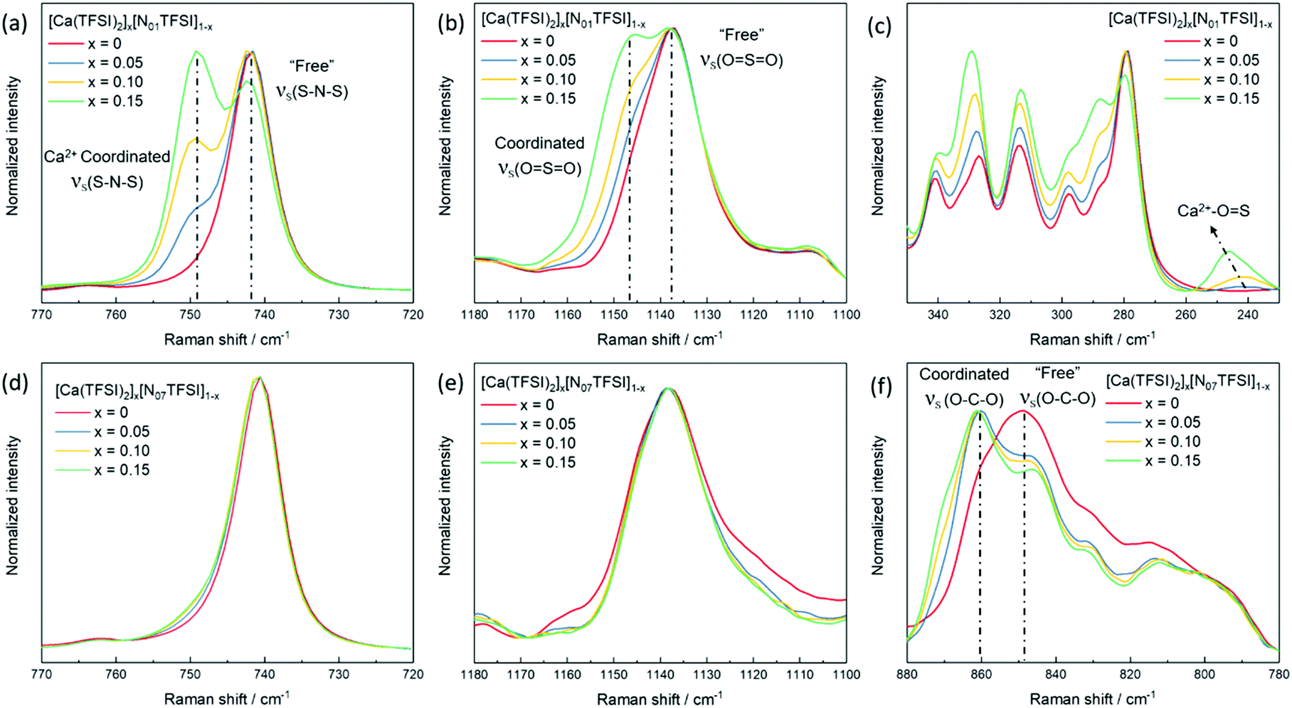 | ||
| Fig. 2 Raman spectra of [Ca(TFSI)2]x[N01TFSI]1−x (a–c) in comparison with [Ca(TFSI)2]x[N07TFSI]1−x (d–f). | ||
Interestingly, in the νs(SNS) and νs(SO2) vibrations and the low energy intermolecular interaction regions of the N07TFSI-based electrolytes (Fig. 2d, e and Fig. S2 (ESI†), respectively), no (or rather weak) evidence for the Ca2+ ion coordinating with the TFSI− anion is observed. However, the broad C–O–C stretching feature centered at 849 cm−1 shifts to 860 cm−1 as the Ca2+ ion content increases (Fig. 2f), which is then attributed to the Ca2+ ion coordinated with the C–O–C groups in the alkoxy chains of the N07 ammonium cation.36,37 The comparison of the Raman spectra of the N01TFSI electrolytes (Fig. 2a–c) and the N07TFSI electrolytes (Fig. 2e and f) clearly indicates that the alkoxy-functionalized ammonium cation with seven oxygen atoms can effectively displace TFSI− from the Ca2+ ion coordination sphere. This is consistent with our previous report of Mg2+-ion speciation in similar ILs, in which this displacement was found to improve the reversibility of Mg electrochemical deposition/dissolution process.31 Herein, the displacement of TFSI− from the Ca2+ coordination sphere is revisited below in comparing the electrochemical deposition/dissolution of Ca in the four ILs.
The solvation structure of Ca-ion speciation in the IL electrolytes was further identified by single-crystal X-ray diffraction. Colourless, transparent crystals were obtained from oversaturated solutions of Ca(TFSI)2 in Pyr1201TFSI and N01TFSI. The [Pyr1201]2[Ca(TFSI)4] compound crystallizes in the monoclinic space group P21/c. Its crystal packing diagram is shown in Fig. 3. The Ca2+ ion is coordinated in a distorted square antiprism geometry by eight oxygen atoms of four different TFSI− anions and the isolated square antiprismatic [Ca(TFSI)4]2− complexes are separated by two Pyr1201+ cations to compensate the charge. All TFSI− ligands show a cisoid conformation and are coordinated in a bidentate geometry via one oxygen atom from each SO2 group. The crystal structure of [Pyr1201]2[Ca(TFSI)4] is similar to that previously reported for the [Pyr14]2[Ca(TFSI)4] compound,27 which is the only other reported crystal structure containing Ca(TFSI)2 to the best of our knowledge. Substitution of the alkyl-functionalized pyrrolidinium cation with the alkoxy-functionalized ammonium cation has been shown to reduce the lattice energy and suppress crystallization of the IL solution. Correspondingly, the crystals obtained from N01TFSI electrolyte are more fragile than those from [Pyr1201]2[Ca(TFSI)4], which makes it impossible to obtain a meaningful XRD analysis.
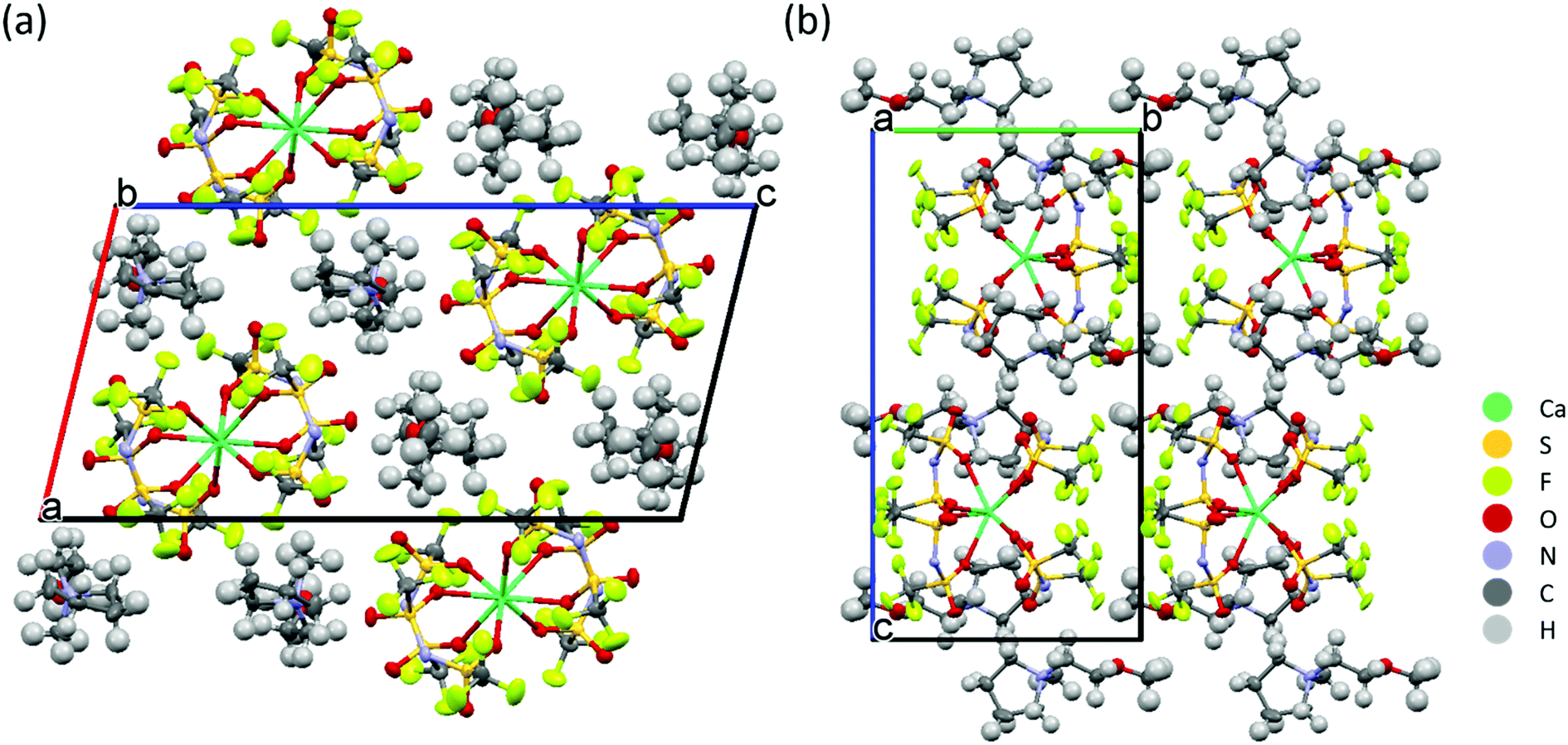 | ||
| Fig. 3 Projection of the crystal structure of [Pyr1201]2[Ca(TFSI)4] along the crystallographic (a) b- and (b) a-axes. | ||
Previous studies about Mg have demonstrated that the nature of the Mg2+-ion species is one of the keys to successful Mg deposition/dissolution in IL media.28 For IL-based electrolytes containing only TFSI− anion, Mg ions are typically found as Mg(TFSI)3−.25,36 The electrochemical deposition and dissolution of Mg from this complex is not reversible since the TFSI− anion is not stable towards reduction.38 However, just displacing TFSI− from the coordination sphere of Mg2+ is insufficient to achieve the reversible Mg2+/Mg electrochemistry.32 To ensure the removal of any residual impurities is vital as well, which prevents the formation of an ion-blocking SEI layer. For example, the Mg deposition/dissolution in electrolytes based on ILs and containing TFSI− anion occurs only when Mg(TFSI)2 is replaced with Grignard reagent or Mg(BH4)2, both of which can serve as scavengers of water traces.22,32 Inspired by the Mg results, we also investigated Ca deposition/dissolution in the relatively reducing electrolyte solutions based on calcium borohydride dissolved in ILs. Unfortunately, due to the limited solubility of the Ca(BH4)2 in the ILs, we could not quantitatively investigate the coordination sphere of Ca-ion speciation in such electrolytes. However, the thermograms (Fig. S3, ESI†) and Raman spectra (Fig. S4, ESI†) of the Ca(BH4)2/IL electrolytes suggest that the solvation structure of Ca-ion speciation is similar to that of the Ca(TFSI)2/IL electrolytes. Specifically, the TFSI− anion is coordinated to the Ca2+ center in the case of Pyr14TFSI, Pyr1201TFSI, and N01TFSI electrolytes, but is displaced from the Ca2+ ion coordination sphere by polyether chains in the case of N07TFSI electrolyte.
The investigation of Ca plating and stripping in the Ca(BH4)2/IL electrolytes was carried out by cyclic voltammetry (CV) in three-electrode cells, using Au as working electrode (WE) and Ca metal as counter electrode (CE) and reference electrode (RE). As shown in Fig. 4a, an intense current was observed in the cathodic scan of the Pyr14TFSI-, Pyr1201TFSI-, and N01TFSI-based electrolytes. However, no signal corresponding to Ca stripping could be detected in the anodic scan of all these three electrolytes. The only existing study about IL-based electrolytes for Ca batteries reported a similar CV curve of Ca(TFSI)2/N01TFSI electrolyte, in which the intense cathodic current has been attributed to Ca deposition.39 However, according to the above-mentioned Raman investigation on the solvation structure of Ca-ion speciation in N01TFSI, we believe this intense current should be attributed to TFSI− anion fragmentation.38 Fig. S5a (ESI†) shows the deposition product obtained from [Ca(BH4)2]0.05[N01TFSI]0.95. EDX elemental analysis reveals a high content of F (21.4%) and S (21.1%) in the deposited product, which is characteristic of TFSI− anion decomposition and leads to surface fouling. Interestingly, when the TFSI− anions are displaced from the Ca2+ ion coordination sphere by the polyether chains, as in the N07TFSI-based electrolyte, typical reversible metal plating and stripping voltammograms are observed (Fig. 4b), although the peaks are centered at around −1.25 V versus Ca metal pseudo-RE. In order to calibrate this potential shift, CV measurements were performed using three-electrode cells employing Li metal pseudo-RE and leakless Ag/AgCl RE. As shown in Fig. S6 (ESI†), the plating/stripping process is centered at ca. −0.1 V vs. Li metal pseudo-RE or −3.3 V vs. Ag/AgCl RE. Although the reason for the significant potential shift remains unclear, it seems the shift might related to the Ca metal pseudo-RE passivation rather than the electrolyte ohmic drop.40,41
 | ||
| Fig. 4 (a and b) Cyclic voltammograms for the Ca deposition and dissolution reaction in different Ca(BH4)2/IL electrolytes. Working electrode: Au, counter and reference electrodes: Ca. (c and d) Powder X-ray diffraction pattern (c) and SEM image (d) of the Ca deposits obtained from [Ca(BH4)2]0.05[N07TFSI]0.95 electrolyte. | ||
To confirm whether the reversible redox process observed in the CV scans of [Ca(BH4)2]0.05[N07TFSI]0.95 electrolyte corresponds to Ca metal deposition/dissolution processes, galvanostatic deposition was carried out at a constant current of 0.2 mA cm−2 on a copper substrate. The gray-white deposit on the Cu electrode was collected for powder X-ray diffraction (PXRD) and scanning electron microscopy (SEM). The PRXD pattern of the deposit is shown in Fig. 4c. The dominant deposition product is Ca metal in the cubic phase, along with a small amount of Ca(OH)2, which may generate from atmosphere contamination. It is worth to mention that Ca metal may have a propensity for dendrite formation.16 In fact, as shown in Fig. 4d, the SEM image of the Ca deposit reveals a dendritic morphology, which is distinctly differs from the smooth hemispherical morphology of the Mg deposit obtained from the analogous Mg(BH4)2/N07TFSI electrolyte.31 Another point worth noting is that the coulombic efficiency of Ca plating and stripping process is only around 37% in [Ca(BH4)2]0.05[N07TFSI]0.95 electrolyte, which indicates the redox process is accompanied by side reactions. Nonetheless, these side-reactions do not block the Ca plating and stripping processes. Thus, in contrast to the surface blocking TFSI− fragmentation, the degradation products of the side-reactions occurring in the N07TFSI-based electrolyte form a Ca-ion conductive SEI layer. The EDX analysis of the deposits obtained from the [Ca(BH4)2]0.05[N07TFSI]0.95 electrolyte shows a significantly reduced fraction of F and S elements (2.0% and 1.4%, respectively), indicating that the unwanted TFSI− anion decomposition is effectively suppressed (Fig. S5b, ESI†). Nevertheless, large amounts of C and O elements are evidenced, which appear to be the main components of the conductive SEI layer.
To gain further information on the plating process, the surface chemistry of the Ca deposit was characterized in detail by X-ray photoelectron spectroscopy (XPS). The XPS survey spectrum in Fig. S7 (ESI†) confirms the presence of large amounts of C and O and minor amounts of F, corroborating the EDX results mentioned above. Representative high-resolution XPS detail spectra including the corresponding fits are shown in Fig. 5. The Ca 2p detail spectrum (Fig. 5a) shows two features centered at 351.2 and 347.7 eV, which could correspond to the Ca or CaF2 2p1/2 and Ca 2p3/2 peaks.42,43 In the C 1s spectrum (Fig. 5b), four peaks can be discerned at binding energies of 290.2, 288.1, 286.0, and 284.8 eV, which can be assigned to ![[C with combining low line]](https://www.rsc.org/images/entities/char_0043_0332.gif) –F, –OO, –O– and –(C,H) groups, respectively.44–46 The O 1s spectrum in Fig. 5c displays three obvious peaks located at 533.5, 532.3 and 531.2 eV, corresponding to the O
–F, –OO, –O– and –(C,H) groups, respectively.44–46 The O 1s spectrum in Fig. 5c displays three obvious peaks located at 533.5, 532.3 and 531.2 eV, corresponding to the O![[double bond, length as m-dash]](https://www.rsc.org/images/entities/char_e001.gif) C–
C–![[O with combining low line]](https://www.rsc.org/images/entities/char_004f_0332.gif) , C––C and C–O groups, respectively, which is in agreement with the C 1s spectrum.47,48 It should be mentioned that small features at binding energies corresponding to
, C––C and C–O groups, respectively, which is in agreement with the C 1s spectrum.47,48 It should be mentioned that small features at binding energies corresponding to ![[F with combining low line]](https://www.rsc.org/images/entities/char_0046_0332.gif) –M (685.5 eV, Fig. 5d) and –M (530.3 eV, Fig. 5c) were also observed, suggesting the existence of rather small amounts of the inorganic compounds CaF2 and CaO in the SEI layer. It can be noticed that the C–O–C group is dominating the C 1s spectrum as well as the O 1s spectrum, which is a typical characteristic of poly(ethylene oxide)-like compounds.44,45 Thus, based on the element content and surface chemistry analysis of Ca deposits obtained from the [Ca(BH4)2]0.05[N07TFSI]0.95 electrolyte, we propose that the degradation products of Ca-ion speciation in this IL-based electrolyte form a protective SEI layer mainly composed of organic polyether chains. This organic-rich, but inorganic-poor SEI layer seems to be Ca-ion conductive enabling the Ca metal dissolution/deposition processes.21,49
–M (685.5 eV, Fig. 5d) and –M (530.3 eV, Fig. 5c) were also observed, suggesting the existence of rather small amounts of the inorganic compounds CaF2 and CaO in the SEI layer. It can be noticed that the C–O–C group is dominating the C 1s spectrum as well as the O 1s spectrum, which is a typical characteristic of poly(ethylene oxide)-like compounds.44,45 Thus, based on the element content and surface chemistry analysis of Ca deposits obtained from the [Ca(BH4)2]0.05[N07TFSI]0.95 electrolyte, we propose that the degradation products of Ca-ion speciation in this IL-based electrolyte form a protective SEI layer mainly composed of organic polyether chains. This organic-rich, but inorganic-poor SEI layer seems to be Ca-ion conductive enabling the Ca metal dissolution/deposition processes.21,49
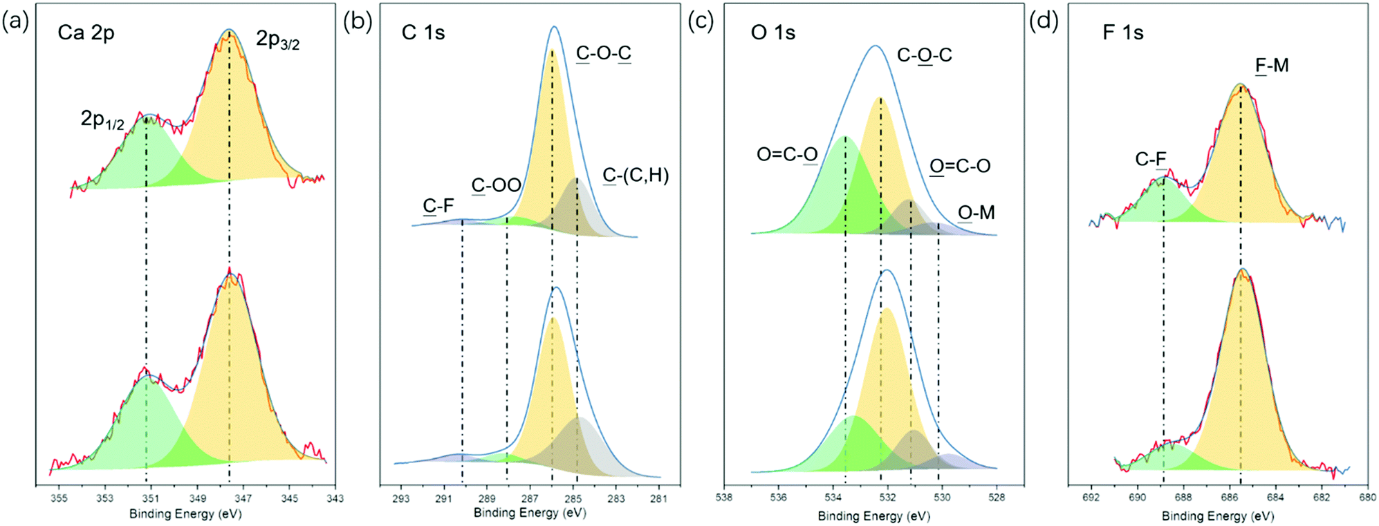 | ||
| Fig. 5 X-ray photoelectron spectra of the Ca 2p (a), C 1s (b), O 1s (c), and F 1s (d) regions of deposits obtained from [Ca(BH4)2]0.05[N07TFSI]0.95 electrolyte before (upper) and after 10 min sputtering (bottom). | ||
To further study the effect of Ca-ion speciation on the electrolyte stability, DFT calculations were performed to evaluate the energy levels for the Ca-ion speciation considered in this work. The optimized configurations and interaction energies of Ca-BH4, Ca-TFSI, and Ca-N07 clusters are given in Fig. S8 and Table S1 (ESI†). A comparison between the evolution of clusters consisting of Ca2+ coordinated by N07+ cations or TFSI− anions is given in Fig. 6. In the case of the TFSI− coordinated Ca2+ cluster, both the single- and the two-electron reduction processes result in the decomposition of the TFSI− anions, which is consistent with previously reported reduction processes of the TFSI− coordinated Mg2+ cluster.31,38,50 It is interesting to notice that the TFSI− anion decomposes through C–S bond cleavage in the case of Mg while it decomposes through N–S bond in the presence of Ca2+. This process leads to the formation of an insulating SEI layer, which is responsible for the poor performance of electrolytes containing IL with the TFSI− anion. On the contrary, when the Ca2+ is coordinated by N07+ cations, the injection of a single electron results in the initial formation of Ca˙+ radical cation. This highly reactive species is actually stabilized by the interaction with the N07+ cations, and a minimum of the potential energy surface can be found. At this stage, two paths are possible leading to fundamentally different results. In the first case, overcoming an energy barrier of ∼40 kJ mol−1, an electron transfers from the metal to one of the coordinating cations may occur, resulting in the latter decomposition by the ejection of one of the diethylene glycol branches in the form of a radical. Following, the Ca2+ is restored, which is now coordinated by a N07+ cation and a neutral N05 ternary amine. The expelled diethylene glycol radical could start a radical polymerization resulting in the formation of the polymeric protective and conducting SEI layer experimentally observed. In the second case, another electron is injected in the system, forming metallic Ca, which poorly interacts with the cations. This results in breaking the solvation cage enabling the Ca plating on the electrode. Similarly, if two electrons are simultaneously injected in the N07+ coordinated Ca2+ cluster the final product is Ca deposition. The two-electron transfer is energetically more favorable in the first step, but the single-electron process leads to a final state that is much lower in energy. According to the Boltzmann Distribution, the two-electron process is about 40 times more likely to take place.
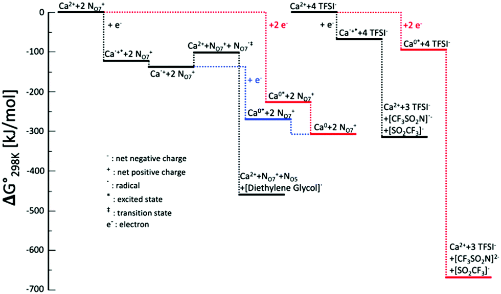 | ||
| Fig. 6 Energy levels for the Ca-ion speciation considered in this work. The zero is defined as the energy at the equilibrated geometry of the ions interacting with Ca2+. Black lines refer to single-electron processes; red lines refer to one-step two-electrons processes; blue lines refer to two-steps two-electron processes. | ||
Having demonstrated the plating and stripping of Ca, we used the [Ca(BH4)2]0.05[N07TFSI]0.95 electrolyte to assemble a proof-of-concept rechargeable Ca battery coupling a Ca metal anode and a V2O5 aerogel cathode. The bilayered-V2O5 has been used as the cathode host materials for various cations, e.g., Li+,51 Na+,52 K+,53 Zn2+,54 Mg2+ ions,31 and its ability has also been successfully demonstrated for reversible intercalation/de-intercalation of Ca2+ ion.55–57 However, compared to monovalent cations, multivalent ions suffer from high migration energy barriers.58 Correspondingly, the proof-of-concept Ca/V2O5 cell is demonstrated at a low current density of 20 mA g−1. The oxidation stability of the [Ca(BH4)2]0.05[N07TFSI]0.95 electrolyte is approximately 2.4 V versus Ca metal pseudo-RE (Fig. S9, ESI†). Thus, the Ca/V2O5 cell was cycled between 0.01 V and 2 V. Fig. 7 shows the voltage profiles upon Ca2+ intercalation/de-intercalation in V2O5via galvanostatic discharge/charge test. The discharge/charge mean potentials were calculated to be 0.85/1.24 V vs. Ca pseudo-reference, respectively. The cathode material delivered a remarkable initial discharge capacity of 332 mA h g−1 followed with a charge capacity of 244 mA h g−1. From the second cycle to the fourth cycle the capacity stabilized at around 250 mA h g−1. It is important to notice that the coulombic efficiency (defined as the ratio between the discharge and charge capacities, i.e., Qdis/Qch) is always higher than 100%. This is a clear indication that side reactions occur delivering additional capacity during discharge. Nonetheless, despite the limited cyclability and reversibility, these results indicate the potential of rechargeable Ca batteries using Ca metal anode and IL electrolyte for the first time. Most important, the successful demonstration implies the feasibility of using a polymeric, artificial SEI layer to facilitate Ca2+ diffusion.
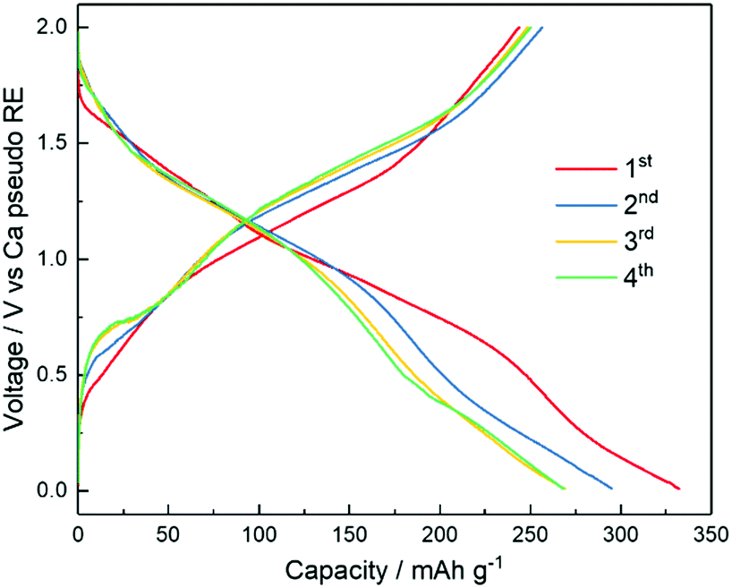 | ||
| Fig. 7 Voltage profiles during galvanostatic charge and discharge (20 mA g−1 of V2O5) of a rechargeable Ca battery with [Ca(BH4)2]0.05[N07TFSI]0.95 as the electrolyte, and Ca and V2O5 as the negative and positive electrodes, respectively. | ||
Conclusions
Several mixtures of Ca salts and ILs have been characterized as electrolytes for Ca-batteries. DSC thermograms and Raman spectroscopic analysis show as the alkoxy-functionalized ammonium cation bearing seven ether oxygen atoms can effectively displace TFSI− from the Ca2+ ion coordination sphere. This is one of the keys for the successful Ca deposition/dissolution observed in such an IL-based electrolyte. Most importantly, XPS, EDX and DFT results suggest the formation of an organic-rich, but inorganic-poor SEI layer instead of the typical inorganic compound-based layer, as the strategy to facilitate Ca2+ diffusion to and from the metal electrode. As a proof-of-concept, it is demonstrated that the alkoxy-functionalized IL-based electrolyte enables the first direct demonstration of a rechargeable Ca metal cell, employing a V2O5 positive electrode, taking advantage of the PEO-like SEI formation and the TFSI− displacement from the coordination of the Ca2+ cations. The reported results highlight the excellent potential of alkoxy-functionalized IL-based electrolyte as an attractive model system to control speciation of metal ions and ionic interaction in the electrolyte. It is expected that the proof-of-concept Ca/V2O5 cell provides guidance for future efforts to design artificial SEI-protected, alkaline-earth metal anodes enabling the improvement of multivalent battery chemistries.Experimental
Electrolyte preparation and characterization
Calcium bis(trifluoromethanesulfonyl)imide (Ca(TFSI)2, Solvionic) and, calcium borohydride (Ca(BH4)2, Sigma Aldrich) were used as received. The Pyr14TFSI, Pyr1201TFSI, N01TFSI, and N07TFSI ionic liquids were prepared following the procedure described in the literature.31 Briefly, the TFSI-based ILs were synthesized using a two-step synthesis procedure, involving the direct alkylation of pyrrolidinium or amine to form the bromide precursor, which is subject to anion exchange with Lithium bis(trifluoromethanesulfonyl)imide in aqueous solution. The hydrophobic ILs were rinsed several times with deionized water to eliminate the water-soluble impurities, LiBr and excess Li salt. Then the ILs were vacuum dried for 2 days (below 10−7 mbar, evacuated using a turbomolecular pump). The electrolyte solutions were prepared by mixing appropriate amounts of calcium salt and IL in an argon-filled glove box (MBRAUN), with oxygen and water contents lower than 0.1 ppm. The ILs and electrolyte solutions were all dried under vacuum using a turbomolecular pump (below 10−7 mbar). The water content of the ILs and electrolyte solutions was less than 5 ppm (detection limit) as determined by Karl Fischer titration.DSC measurements were performed using a differential scanning calorimeter (TA Instruments Q2000) with liquid N2 cooling. The samples were hermetically sealed in aluminum pans in the glove box. The thermal treatment included cycling from −140 to 100 °C at a rate of 5 °C min−1. The Raman measurements were recorded on a combined Raman-FTIR spectrometer (RAM II FT-Raman module of Bruker Vertex70) equipped with a laser wavelength of 1064 nm and laser power of 300 mW. The collected spectra are the average of 500 scans at an optical resolution of 2 cm−1. Single crystal XRD was performed on a Bruker D8 Quest with a Photon II detector. Surface morphology of electrodeposited calcium was studied using scanning electron microscopy (ZEISS 1550VP). All samples recovered from the cells were transferred to the microscope in Ar atmosphere using an airtight transfer box (Sample Transfer Shuttle, SEMILAB). Elemental analysis and elemental mapping were performed by using the EDX spectroscopy. Powder XRD was carried out with a Bruker D8 Advance (Cu-Kα radiation with a wavelength of 0.154 nm) in an air-sensitive holder. XPS measurements were conducted in an ultrahigh vacuum surface analysis system by monochromatized Al Kα (1486.6 eV) radiation (PHI 5800 MultiTechnique ESCA System, Physical Electronics) at a base pressure of 10−10 mbar. For XPS characterization, electrodes were disassembled inside the glovebox and dip-washed with DMC for a few seconds to remove electrolyte residuals. Then, they were dried under vacuum in the glovebox antechamber for 30 min and mounted on the XPS sample holder. In order to prevent air exposure and surface contamination, all samples were transferred to the XPS load-lock chamber under inert gas atmosphere by means of an airtight transfer vessel. During data acquisition of survey and detail spectra, the constant-analyzer-energy mode was used at 93.9 and 29.35 eV energy passes, respectively. For elemental depth profiling, the outer surface layers were removed by Ar+ sputtering (ISp ≈ 1 mA; USp = 5 kV) for 10 min. Peak fitting was done with the CasaXPS software using Shirley background subtraction and mixed Gaussian–Lorentzian peak shapes.
Electrochemical characterization
Cyclic voltammograms were acquired using three electrodes glass cell in an argon-filled glove box. A gold disk electrode (1 mm diameter) was used as working electrode while calcium metal (purchased from ZRindustrial, purity of 99.8%) was used for the reference and counter electrodes. The calcium ribbon surface was cleaned with a razor blade. The tests were conducted using a VMP3 galvanostat/potentiostat (BioLogic). The galvanostatic calcium deposition on Cu foil substrates (about 1 mA h cm−2 at a current density of 0.2 mA cm−2) was performed inside the glovebox. The deposits were dip-washed with DMC for a few seconds and dried under vacuum in the glovebox antechamber for 30 min. After, the deposits were collected from the Cu foil and mounted in an air-tight XRD sample holder. The V2O5 aerogel cathode material was prepared according to the reported microwave driven reaction.52,53 The cathodes were composed of 70 wt% active material, 20 wt% carbon black (Super C65, IMERYS), and 10 wt% polyacrylic acid (Sigma-Aldrich, average Mv of ∼1 250![[thin space (1/6-em)]](https://www.rsc.org/images/entities/char_2009.gif) 000) binder with aluminum foil current collectors. The average mass loading of active material was around 1.4 mg cm−2. Three electrode Swagelock cells were assembled in the argon-filled glovebox with water and oxygen content below 0.1 ppm. Whatman GF/D glass fiber separators were soaked with the electrolyte and Ca metal was used as the counter and reference electrodes. Galvanostatic cycling was conducted using a battery tester (Maccor, model 4300). All electrochemical tests were performed at 20 °C.
000) binder with aluminum foil current collectors. The average mass loading of active material was around 1.4 mg cm−2. Three electrode Swagelock cells were assembled in the argon-filled glovebox with water and oxygen content below 0.1 ppm. Whatman GF/D glass fiber separators were soaked with the electrolyte and Ca metal was used as the counter and reference electrodes. Galvanostatic cycling was conducted using a battery tester (Maccor, model 4300). All electrochemical tests were performed at 20 °C.
Computational method
DFT calculations were performed using Gaussian0959 at CAM-B3LYP/6-31+G* level of theory. The geometries for the starting systems, i.e. Ca2+ + 2 NO7+ and Ca2+ + 4 TFSI−, were hand-drawn using Avogadro60 and then optimized. To obtain the Gibbs free energy values, for every molecular arrangement a vibrational frequency calculation was performed. From that point, we considered two different electron transfer scenarios. The first where a single electron is injected, and the second where an electron pair is simultaneously added. To achieve a realistic simulation of the system reduction, we did not allow for nuclei relaxation after electron acquisition, being the transfer faster than atomic vibrations. The excited clusters obtained this way were found to have energies lower than the starting state, meaning that the process will happen, but they also have two or more negative vibration frequencies, indicating that the molecular conformation needs to relax to accommodate the electron(s). We then allowed for nuclear relaxation, and for all the clusters no imaginary frequencies were observed, with the exception of the systems Ca2+ + NO7+ + NO7˙‡ system, where a single negative vibration frequency was found, indicating a saddle-point in the potential energy surface, characteristic of a transition state.Conflicts of interest
There are no conflicts to declare.Acknowledgements
The research leading to these results has received funding from the H2020 Programme (H2020-FETOPEN-2018-2019-2020) under grant agreement no. 828902, Project “VIDICAT Versatile Ionomers For Divalent Calcium Batteries”. All authors acknowledge the support support Initiative and Networking Fund of the Helmholtz Association within the Network of Excellence on post-Lithium batteries (ExNet-0035). X. Liu gratefully acknowledges financial support from the China Scholarship Council.References
- C. Vaalma, D. Buchholz, M. Weil and S. Passerini, Nat. Rev. Mater., 2018, 3, 18013, DOI:10.1038/natrevmats.2018.13.
- W. Xu, J. Wang, F. Ding, X. Chen, E. Nasybulin, Y. Zhang and J. G. Zhang, Energy Environ. Sci., 2014, 7, 513–537 RSC.
- J. Muldoon, C. B. Bucur and T. Gregory, Chem. Rev., 2014, 114, 11683–11720 CrossRef CAS PubMed.
- R. Deivanayagam, B. J. Ingram and R. Shahbazian-Yassar, Energy Storage Mater., 2019, 21, 136–153 CrossRef.
- M. E. Arroyo-De Dompablo, A. Ponrouch, P. Johansson and M. R. Palacín, Chem. Rev. DOI:10.1021/acs.chemrev.9b00339.
- G. A. Elia, K. Marquardt, K. Hoeppner, S. Fantini, R. Lin, E. Knipping, W. Peters, J.-F. Drillet, S. Passerini and R. Hahn, Adv. Mater., 2016, 28(35), 7564, DOI:10.1002/adma.201601357.
- R. Deivanayagam, B. J. Ingram and R. Shahbazian-Yassar, Energy Storage Mater., 2019, 21, 136, DOI:10.1016/j.ensm.2019.05.028.
- P. Canepa, G. Sai Gautam, D. C. Hannah, R. Malik, M. Liu, K. G. Gallagher, K. A. Persson and G. Ceder, Chem. Rev., 2017, 117, 4287–4341 CrossRef CAS PubMed.
- E. Peled, J. Electrochem. Soc., 1979, 126, 2047–2051 CrossRef CAS.
- E. Peled and S. Menkin, J. Electrochem. Soc., 2017, 164, A1703–A1719 CrossRef CAS.
- D. Aurbach, R. Skaletsky and Y. Gofer, J. Electrochem. Soc., 1991, 138, 3536–3545 CrossRef CAS.
- R. J. Staniewicz, J. Electrochem. Soc., 1980, 127, 782–789 CrossRef CAS.
- D. Aurbach, Z. Lu, A. Schechter, Y. Gofer, H. Gizbar, R. Turgeman, Y. Cohen, M. Moshkovich and E. Levi, Nature, 2000, 407, 724–727 CrossRef CAS.
- M. Westerhausen, A. Koch, H. Görls and S. Krieck, Chem. – Eur. J., 2017, 23, 1456–1483 CrossRef CAS PubMed.
- A. Ponrouch, C. Frontera, F. Bardé and M. R. Palacín, Nat. Mater., 2016, 15, 169–172 CrossRef CAS PubMed.
- A. Shyamsunder, L. E. Blanc, A. Assoud and L. F. Nazar, ACS Energy Lett., 2019, 4, 2271–2276 CrossRef CAS.
- Z. Li, O. Fuhr, M. Fichtner and Z. Zhao-Karger, Energy Environ. Sci., 2019, 12, 3496, 10.1039/c9ee01699f.
- M. Wang, C. Jiang, S. Zhang, X. Song, Y. Tang and H. M. Cheng, Nat. Chem., 2018, 10, 667–672 CrossRef CAS PubMed.
- K. Ta, R. Zhang, M. Shin, R. T. Rooney, E. K. Neumann and A. A. Gewirth, ACS Appl. Mater. Interfaces, 2019, 11, 21536–21542 CrossRef CAS PubMed.
- N. T. Hahn, J. Self, T. J. Seguin, D. M. Driscoll, M. A. Rodriguez, M. Balasubramanian, K. A. Persson and K. R. Zavadil, J. Mater. Chem. A, 2020, 8, 7235–7244 RSC.
- S. B. Son, T. Gao, S. P. Harvey, K. X. Steirer, A. Stokes, A. Norman, C. Wang, A. Cresce, K. Xu and C. Ban, Nat. Chem., 2018, 10, 532–539 CrossRef CAS PubMed.
- G. A. Giffin, J. Mater. Chem. A, 2016, 4, 13378–13389 RSC.
- M. Watanabe, M. L. Thomas, S. Zhang, K. Ueno, T. Yasuda and K. Dokko, Chem. Rev., 2017, 117, 7190–7239 CrossRef CAS PubMed.
- W. A. Henderson and S. Passerini, Chem. Mater., 2004, 16, 2881–2885 CrossRef CAS.
- G. A. Giffin, A. Moretti, S. Jeong and S. Passerini, J. Phys. Chem. C, 2014, 118, 9966–9973 CrossRef CAS.
- P. Hartman and H. K. Chan, Acta Crystallogr., Sect. A: Cryst. Phys., Diffr., Theor. Gen. Crystallogr., 1976, 32, 751–767 CrossRef.
- A. Babai and A. V. Mudring, Inorg. Chem., 2006, 45, 3249–3255 CrossRef CAS PubMed.
- X. Gao, F. Wu, A. Mariani and S. Passerini, ChemSusChem, 2019, 12, 4185–4193 CrossRef CAS PubMed.
- J. D. Forero-Saboya, E. Marchante, R. B. Araujo, D. Monti, P. Johansson and A. Ponrouch, J. Phys. Chem. C, 2019, 123, 29524–29532 CrossRef CAS PubMed.
- M. Castriota, T. Caruso, R. G. Agostino, E. Cazzanelli, W. A. Henderson and S. Passerini, J. Phys. Chem. A, 2005, 109, 92–96 CrossRef CAS PubMed.
- X. Gao, A. Mariani, S. Jeong, X. Liu, X. Dou, M. Ding, A. Moretti and S. Passerini, J. Power Sources, 2019, 423, 52–59 CrossRef CAS.
- T. Watkins, A. Kumar and D. A. Buttry, J. Am. Chem. Soc., 2016, 138, 641–650 CrossRef CAS PubMed.
- N. N. Rajput, T. J. Seguin, B. M. Wood, X. Qu and K. A. Persson, Elucidating Solvation Structures for Rational Design of Multivalent Electrolytes—A Review, Springer International Publishing, 2018, vol. 376 Search PubMed.
- K. Fumino, A. Wulf and R. Ludwig, Angew. Chem., Int. Ed., 2008, 47, 3830–3834 CrossRef CAS PubMed.
- A. Wulf, K. Fumino, R. Ludwig and P. F. Taday, ChemPhysChem, 2010, 11, 349–353 CrossRef CAS PubMed.
- T. Watkins and D. A. Buttry, J. Phys. Chem. B, 2015, 119, 7003–7014 CrossRef CAS PubMed.
- D. Brouillette, D. E. Irish, N. J. Taylor, G. Perron, M. Odziemkowski and J. E. Desnoyers, Phys. Chem. Chem. Phys., 2002, 4, 6063–6071 RSC.
- N. N. Rajput, N. Sa, X. Qu, A. K. Burrell and K. A. Persson, J. Am. Chem. Soc., 2015, 3411–3420 CrossRef CAS PubMed.
- T. Shiga, Y. Kato and Y. Hase, J. Mater. Chem. A, 2017, 5, 13212–13219 RSC.
- D. S. Tchitchekova, D. Monti, P. Johansson, F. Bardé, A. Randon-Vitanova, M. R. Palacín and A. Ponrouch, J. Electrochem. Soc., 2017, 164, A1384–A1392 CrossRef CAS.
- R. Dugas, J. D. Forero-Saboya and A. Ponrouch, Chem. Mater., 2019, 31, 8613, DOI:10.1021/acs.chemmater.9b02776.
- M. Wang, C. Jiang, S. Zhang, X. Song, Y. Tang and H. M. Cheng, Nat. Chem., 2018, 10, 667–672 CrossRef CAS PubMed.
- P. Layrolle and A. Lebugle, Chem. Mater., 1996, 8, 134–144 CrossRef CAS.
- P. Louette, F. Bodino and J.-J. Pireaux, Surf. Sci. Spectra, 2005, 12, 59–63 CrossRef CAS.
- A. Bratek-Skicki, P. Eloy, M. Morga and C. Dupont-Gillain, Langmuir, 2018, 34, 3037–3048 CrossRef CAS PubMed.
- B. Qin, S. Jeong, H. Zhang, U. Ulissi, D. Vieira Carvalho, A. Varzi and S. Passerini, ChemSusChem, 2019, 12, 208–212 CrossRef CAS.
- M. Zarrabeitia, L. Gomes Chagas, M. Kuenzel, E. Gonzalo, T. Rojo, S. Passerini and M. Á. Muñoz-Márquez, ACS Appl. Mater. Interfaces, 2019, 11, 28885–28893 CrossRef CAS PubMed.
- M. Hekmatfar, A. Kazzazi, G. G. Eshetu, I. Hasa and S. Passerini, ACS Appl. Mater. Interfaces, 2019, 11, 43166–43179 CrossRef CAS.
- Q. Pang, A. Shyamsunder, B. Narayanan, C. Y. Kwok, L. A. Curtiss and L. F. Nazar, Nat. Energy, 2018, 3, 783–791 CrossRef CAS.
- Y. Yu, A. Baskin, C. Valero-Vidal, N. T. Hahn, Q. Liu, K. R. Zavadil, B. W. Eichhorn, D. Prendergast and E. J. Crumlin, Chem. Mater., 2017, 29, 8504–8512 CrossRef CAS.
- A. Moretti, F. Maroni, I. Osada, F. Nobili and S. Passerini, ChemElectroChem, 2015, 2, 529–537 CrossRef CAS.
- X. Liu, B. Qin, H. Zhang, A. Moretti and S. Passerini, ACS Appl. Energy Mater., 2019, 2, 2786–2793 CrossRef CAS.
- X. Liu, G. A. Elia, X. Gao, B. Qin, H. Zhang and S. Passerini, Batter. Supercaps, 2020, 1–8 Search PubMed.
- P. Senguttuvan, S. D. Han, S. Kim, A. L. Lipson, S. Tepavcevic, T. T. Fister, I. D. Bloom, A. K. Burrell and C. S. Johnson, Adv. Energy Mater., 2016, 6, 1600826, DOI:10.1002/aenm.201600826.
- G. G. Amatucci, F. Badway, A. Singhal, B. Beaudoin, G. Skandan, T. Bowmer, I. Plitz, N. Pereira, T. Chapman and R. Jaworski, J. Electrochem. Soc., 2001, 148, A940 CrossRef CAS.
- M. Hayashi, H. Arai, H. Ohtsuka and Y. Sakurai, J. Power Sources, 2003, 119–121, 617–620 CrossRef CAS.
- M. Hayashi, H. Arai, H. Ohtsuka and Y. Sakurai, Electrochem. Solid-State Lett., 2004, 7, A119, DOI:10.1149/1.1675951.
- G. S. Gautam, P. Canepa, R. Malik, M. Liu, K. Persson and G. Ceder, Chem. Commun., 2015, 51, 13619–13622 RSC.
- M. J. Frisch, G. W. Trucks, H. B. Schlegel, G. E. Scuseria, M. A. Robb, J. R. Cheeseman, G. Scalmani, V. Barone, B. Mennucci, G. A. Petersson, H. Nakatsuji, M. Caricato, X. Li, H. P. Hratchian, A. F. Izmaylov, J. Bloino, G. Zheng, J. L. Sonnenberg, M. Hada, M. Ehara, R. Toyota, K. Fukuda, J. Hasegawa, M. Ishida, T. Nakajima, Y. Honda, O. Kitao, H. Nakai, T. Vreven, J. Montgomery, Jr., J. E. Peralta, F. Ogliaro, M. Bearpark, J. J. Heyd, E. Brothers, K. N. Kudin, V. N. Staroverov, R. Kobayashi, J. Normand, K. Raghavachari, A. Rendell, J. C. Burant, S. S. Iyengar, J. Tomasi, M. Cossi, N. Rega, M. J. Millam, M. Klene, J. E. Knox, J. B. Cross, V. Bakken, C. Adamo, J. Jaramillo, R. Gomperts, R. E. Stratmann, O. Yazyev, A. J. Austin, R. Cammi, C. Pomelli, J. W. Ochterski, R. L. Martin, K. Morokuma, V. G. Zakrzewski, G. A. Voth, P. Salvador, J. J. Dannenberg, S. Dapprich, A. D. Daniels, Ö. Farkas, J. B. Foresman, J. V. Ortiz, J. Cioslowski, D. J. Fox, Gaussian16, Gaussian Inc., Wallingford CT, 2016 Search PubMed.
- M. D. Hanwell, D. E. Curtis, D. C. Lonie, T. Vandermeersch, E. Zurek and G. R. Hutchison, J. Cheminform., 2012, 4, 17 CrossRef CAS PubMed.
Footnote |
| † Electronic supplementary information (ESI) available. CCDC1991206. For ESI and crystallographic data in CIF or other electronic format see DOI: 10.1039/d0ee00831a |
| This journal is © The Royal Society of Chemistry 2020 |