Emerging aqueous two-phase systems: from fundamentals of interfaces to biomedical applications
Youchuang
Chao
 and
Ho Cheung
Shum
 *
*
Department of Mechanical Engineering, The University of Hong Kong, Pokfulam Road, Hong Kong, China. E-mail: ashum@hku.hk
First published on 21st November 2019
Abstract
Aqueous two-phase systems (ATPSs) have been recognized for their applications in extraction, separation, purification, and enrichment of (bio)molecules and cells. Recently, their unique ability to create aqueous–aqueous interfaces through phase separation and the characteristics of these interfaces have created new opportunities in biomedical applications. In this review, we summarize recent progress in understanding the dynamics at aqueous–aqueous interfaces, and in developing interface-assisted design of artificial cells and cyto-mimetic materials, fabrication of cyto- and bio-compatible microparticles, cell micropatterning, 3D bioprinting, and microfluidic separation of cells and biomolecules. We also discuss the challenges and perspectives to leverage the unique characteristics of ATPSs and their interfaces in broader applications.
1. Introduction
Aqueous two-phase systems (ATPSs), also known as all-aqueous systems, are formed by phase separation of an aqueous mixture containing two incompatible additives, such as two incompatible polymers or one polymer and other salts, above critical concentrations.1 In 1896, Martinus Beijerinck for the first time recognized this phenomenon where he found the formation of two immiscible phases after dissolving concentrated starch and gelatin into water.2 ATPSs were rediscovered by Per-Åke Albertsson in the 1950s via utilizing them to concentrate and isolate different types of biological materials.3 Since then, these systems have gained tremendous attention in a variety of areas, such as food industry, chemical synthesis, and biomedical engineering.4 In particular, the simultaneous possession of different affinities, i.e., partitioning, of (bio)molecules towards the two immiscible phases, has established ATPSs in various conventional applications,5–7 such as extraction, separation, purification, and enrichment of cell organelles,9,10 proteins,3 carbon nanotubes,11,12 and metal ions.13,14Thermodynamically, the phase separation of an aqueous mixture occurs when the entropic contribution that favors mixing becomes smaller relative to the enthalpic penalty that opposes it.15 At low concentrations of the two solutes, the aqueous mixture forms a single phase, while at high concentrations, the mixture spontaneously phase-separates into two immiscible phases, as shown in the phase diagram of a typical ATPS (Fig. 1a and b). In the phase diagram, the boundary between the one-phase and two-phase regimes is divided by a binodal curve, and the final compositions of the two aqueous phases after the complete phase separation are given by two end points that are connected with a tie line on the binodal curve (Fig. 1a).16 The two aqueous phases from the phase-separated ATPSs contain a large amount of water, typically over 80% by weight, imparting some distinct properties to ATPSs beyond those of traditional water–organic solvent systems. For instance, ATPSs that are formed by hydrosoluble additives can be made particularly biocompatible because the two solution phases do not involve any organic solvents.8 Moreover, the interfacial tensions of aqueous–aqueous or sometimes known as water–water (w/w) interfaces can be tunable and ultralow, in the range of 10−4–10−1 mN m−1, several orders of magnitude smaller than those of common oil–water (o/w) interfaces.17 Furthermore, the aqueous–aqueous interface is permeable, allowing the free diffusion and exchange of solvent and small molecules, such as water, between the two aqueous phases, which can affect the phase separation behavior.18 These unique properties of ATPSs inspire investigation of new interfacial dynamics and a wide variety of novel biomedical applications.
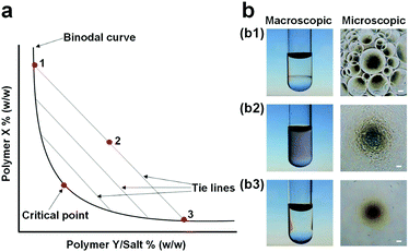 | ||
| Fig. 1 (a) Phase diagram of a typical ATPS: The binodal curve separates the phase diagram into two regions including a single-phase region below the binodal curve and a two-phase region above the binodal curve. The two end points (1, 3) of tie lines correspond to the final compositions of the two immiscible aqueous phases after complete phase separation of the aqueous mixture (2). (b) Images showing three different states of polymer mixtures: (b1) Supercritical (two phases), (b2) critical, and (b3) subcritical (one phase) states. Scale bars are 100 μm. Reproduced with permission.8 Copyright 2017, WILEY-VCH. | ||
In this review, we provide an overview of recent progress in studying w/w interfaces and applications that emerge from the new understanding. We start by first introducing the interfacial dynamics of ATPSs and describe applications that rely on the low interfacial tensions of these systems. Then, we summarize the strategies to fabricate all-aqueous simple and complex emulsion droplets in microfluidic devices. We also discuss existing approaches to stabilize all-aqueous emulsion droplets, particularly focusing on droplets stabilized by colloidal particles. Afterwards, we survey relevant biomaterials and biomedical applications of ATPSs; these include design of artificial cells and cyto-mimetic materials, fabrication of biocompatible materials, cell micropatterning, 3D bioprinting, as well as separation of cells and biomolecules in microfluidic channels. The review will finish with a discussion of the current challenges and future opportunities.
2. Interfacial dynamics of ATPSs
Just as oil and water that are immiscible with each other, two immiscible aqueous phases from the phase-separated ATPS also have an inherent interfacial tension, γ. However, in contrast to the o/w systems, the interfacial tension of the w/w system is typically very low, sometimes less than 1 μN m−1. The low interfacial tension associated with w/w interfaces favors the formation of all-aqueous jets, rather than droplets due to the slow growth of the Rayleigh–Plateau (RP) instability. Theoretically, the effective growth rate (ωr) of the RP instability on a liquid jet (radius: r0, viscosity: μi) surrounded by an immiscible outer fluid (viscosity: μo) can be predicted by linear stability analysis, in the form of19,20 | (1) |
F(x,λ) = x4(4 − λ−1 + 4![[thin space (1/6-em)]](https://www.rsc.org/images/entities/char_2009.gif) ln ln![[thin space (1/6-em)]](https://www.rsc.org/images/entities/char_2009.gif) x) + x6(−8 + 4λ−1) + x8[4 − 3λ−1 − (4 − 4λ−1)ln x) + x6(−8 + 4λ−1) + x8[4 − 3λ−1 − (4 − 4λ−1)ln![[thin space (1/6-em)]](https://www.rsc.org/images/entities/char_2009.gif) x] x] | (2) |
Compared to o/w systems with high interfacial tensions, the growth rate of the linear instability in w/w jets is much smaller, resulting in a significantly slower breakup into droplets and thus providing a possibility to achieve a long and stable liquid jet. Stable w/w jets have been achieved by combining ATPSs with the microfluidic techniques, as demonstrated in the glass capillary-based and polydimethylsiloxane (PDMS)-based microfluidic channels, respectively (Fig. 2a and b).22,23 For instance, when two immiscible phases with an interfacial tension of 0.3 mN m−1, extracted from aqueous mixtures of 7 wt% polyethylene glycol (PEG, molecular weight Mw = 10 kDa) and 10 wt% dextran (DEX, Mw = 500 kDa), are injected into the microfluidic channels, the generated jet can be as long as 160 mm (Fig. 2b). However, in conventional o/w systems, even with addition of sufficient surfactants,24,25 such long jets are still very difficult to achieve. The ability to form long and stable all-aqueous jets in microchannels also provides a very promising approach to fabricate surfactant-free microfibers.26 In addition, the perturbation growth rate measured in experiments is found to be one order of magnitude smaller than that predicted from linear stability analysis, suggesting that a different mechanism might account for the breakup of liquid jets with low interfacial tensions.23,27
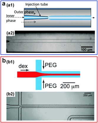 | ||
| Fig. 2 Stable w/w jets formed in microfluidic channels. (a) Schematic showing formation of w/w jets via a glass-capillary-based microfluidic device with a co-flow geometry (a1), and a typical image of the resulting stable jet (a2). Reproduced with permission.22 Copyright 2012, AIP Publishing. (b) Schematic showing formation of w/w jets in a PDMS-based microfluidic device with a flow-focusing geometry (b1), and a typical image of the resulting stable jet (b2). Reproduced with permission.23 Copyright 2012, AIP Publishing. | ||
The ultralow interfacial tension of ATPSs has also enabled the direct visualization of the very minute sound-induced fluid motions at the w/w interface; these motions are otherwise hardly detectable via traditional techniques.28 By applying a sound-induced vibration into the inlet tubing of microfluidic channels, the w/w interface is forced to fluctuate at the same frequency as the imposed sound. Using this approach, musical phrases can be reconstructed by deciphering the corresponding interfacial perturbation structures (Fig. 3a). The highly sensitive response of w/w interfaces to external stimuli has also been utilized to reveal the fluctuations introduced by syringe pumps, which are normally assumed to be stable (Fig. 3b).29,30 Such kind of perturbations can be significant enough to result in nonuniform distributions of droplets produced in droplet microfluidic experiments. Furthermore, the sensitive low-tension w/w interface also provides new a route to control the morphologies of liquid flows. For instance, when a harmonic perturbation produced by a mechanical vibrator is imposed onto the w/w jet phase, tunable periodic structures can be achieved at the liquid–liquid interface.31 By increasing the perturbation frequency, even more complex structures can be achieved (Fig. 3c). These all-aqueous complex structures may be used as templates to fabricate some highly structured all-aqueous liquid devices and biomaterials. In addition to triggering the dynamics of w/w interfaces via sound waves and mechanical vibrations, other external stimuli, such as the electric field, can also be introduced to manipulate the morphology of w/w jets in microfluidic channels, especially for jets with very high viscosity.32,33 While these viscous jets tend to fold,34 the folding can be suppressed by imposing a high voltage along aqueous jets (Fig. 3d). Besides the degree of folding, the jet diameter can also be easily controlled by varying the amplitudes of the applied voltage.
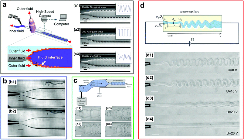 | ||
| Fig. 3 Fluctuation-induced interfacial motions of w/w interfaces in microfluidic channels. (a) Visualization of sound signals at the w/w interface. Left: Schematic of the experimental setup. Right: Profiles of the interface formed by applying musical signals with (a1) a 200 Hz sinusoidal wave, (a2) a 200 Hz square wave, and (a3) a mixed wave composed of 200 Hz and 300 Hz sinusoidal signals. Reproduced with permission.28 Copyright 2014, Springer Nature. (b) Fluctuations at the w/w interface induced by two different pumps: (b1) A syringe pump and (b2) a pressure-driven pump. Scale bars are 200 μm. Reproduced with permission.29 Copyright 2014, Royal Society of Chemistry. (c) Complex liquid structures formed by perturbing the w/w interface. Top: The schematic of the experimental setup. Bottom: Highly corrugated interfaces formed at perturbation frequencies of (c1) 7 Hz, (c2) 9 Hz, (c3) 11 Hz, and (c4) 20 Hz. Scale bars are 200 μm. Reproduced with permission.31 Copyright 2014, Royal Society of Chemistry. (d) Folding and unfolding of the viscous w/w jet induced by adjusting the electric voltage. Top: Schematic of the experimental setup. Reproduced with permission.32 Copyright 2015, American Physical Society. Bottom: Morphologies of the w/w jet under various electric voltages including (d1) 0 V, (d2) 18 V, (d3) 20 V, and (d4) 23 V. Scale bars are 200 μm. Reproduced with permission.33 Copyright 2013, Royal Society of Chemistry. | ||
There has also been increasing interest in manipulating particles at low-tension aqueous–aqueous interfaces. For instance, self-assembly of paramagnetic microparticles into clusters can be easily realized in all-aqueous microfluidic channels (Fig. 4a).35 Microparticles initially dispersed in a DEX phase that reach the aqueous–aqueous interface can self-assemble into clusters because of local magnetic fields from a permanent magnet. If the self-assembled particle clusters are sufficiently large, they will pass through the interface into the PEG phase. However, this is difficult to achieve in o/w interfaces due to their high interfacial tension that has to be overcome by magnetic forces. A systematic study on the size of microparticle clusters can be realized by adjusting the gradient of magnetic fields, and this possibility largely benefits from that ATPSs provide a wide range of low tensions (0.012–0.381 mN m−1) by simply adjusting the concentrations of two solutes. In another work, the ultralow tension also suggests a new approach to improve nanofluidic resistive pulse sensing (RPS).36 If a w/w interface (PEG–DEX) is incorporated inside nanopores, nanoparticles can cross the interface from a high-affinity phase towards a lower-affinity one (Fig. 4b). As a result, compared to the one-phase situation, the incorporation of ATPSs largely improves the detection performances, such as increasing the effective particle size and prolonging translocation time, as well as amplifying the current-blockage signal. Overall, the abilities to manipulate liquid jets and particles indicate that w/w interfaces from ATPSs with low and wide range of interfacial tensions help understand and enrich interfacial dynamics of fluid–fluid systems, such as those in response to external stimuli, as well as enable some applications that require low-tension liquid–liquid systems, such as interfacial assembly of micro- or nanoparticles.
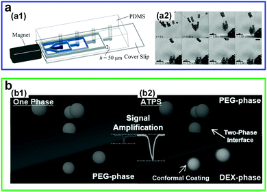 | ||
| Fig. 4 Manipulation of particles by the low-interfacial-tension w/w interface. (a) Controlled self-assembly of microparticles into clusters at the w/w interface by applying a magnetic field gradient in a microchannel: (a1) Schematic of the experimental setup. (a2) Typical microscope images showing the formation of particle clusters at the w/w interface and detachment of particle clusters from the w/w interface. Scale bars are 25 μm. Reproduced with permission.35 Copyright 2016, Royal Society of Chemistry. (b) Schematic showing the amplification of a translocation signal and the reduction of translocation speeds by introducing a w/w interface in nanofluidic resistive pulse sensing (RPS) including: (b1) One phase and (b2) two phases. Reproduced with permission.36 Copyright 2017, Wiley-VCH. | ||
3. All-aqueous emulsion droplets
3.1 Fabrication of all-aqueous single emulsion droplets
Emulsion droplets are important for a wide range of applications such as drug delivery,37 food industry,38 and oil recovery.39 w/w emulsion droplets are particularly attractive due to the all-water environment. Currently, a variety of techniques, such as bulk emulsification40 and droplet microfluidics,24 have been explored for producing emulsion droplets. Among them, droplet microfluidics provides an exquisite control over droplet size and uniformity in microchannels.24 Therefore, the same degree of control observed for microfluidic water–oil droplets is expected to translate to the generation of w/w emulsion droplets. However, due to the fundamental differences between o/w and w/w interfaces, the microfluidic method needs to be modified for generating w/w droplets. In microfluidic channels, the generation of droplets often originates from the RP instability of liquid–liquid interfaces, which can be predicted from eqn (1) and (2).41 Nevertheless, the low interfacial tension of w/w interfaces largely favors the jet formation, making the breakup of these jets into droplets challenging. For instance, an initial linear perturbation in the form of| r = r0 + ε0ei(k/r0)z+ωt, | (3) |
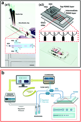 | ||
| Fig. 5 Passive methods to generate w/w emulsion droplets. (a) Droplet formation controlled by the gravity-driven hydrostatic pressure: (a1) A single droplet generator. The scale bar is 200 μm. (a2) An assembled multiple droplet generator. Reproduced with permission.42 Copyright 2016, American Chemical Society. (b) Schematic showing the experimental strategy to precisely control flow rates of two aqueous phases. Reproduced with permission.44 Copyright 2018, American Chemical Society. | ||
To increase the generation rate, another system with four parallel channels assembled onto a single microfluidic device is designed and fabricated (Fig. 5a2). The production rate is increased to more than 50 drops per second, one order of magnitude larger than the production rate of the microfluidic device with a single channel. The introduction of parallel microfluidic channels is therefore suggested as a way to scale up the production of w/w droplets.42 However, for this gravity-driven method, the inlet flow conditions are unstable and change with the height of the fluid column, which is hard to control. Therefore, another microfluidic platform based on this gravity-driven strategy focuses on the precise control of the fluid pressure and simultaneous measurement of the inlet flow rates,44 where the inlet flow rates are used as inputs for feedback control on the droplet property (Fig. 5b). This improved passive method enables the production of w/w droplets with diameters ranging from 14–28 μm and a maximum generation rate as high as 300 Hz. However, due to the strong wetting of the PEG aqueous phase onto the planar PDMS-based microfluidic channels, these passive methods can only use the DEX phase as the dispersed phase and generate DEX-in-PEG emulsion droplets, largely limiting the potential applications of all-aqueous emulsion droplets, such as templated fabrication of poly(ethylene glycol) diacrylate (PEGDA) microparticles. Typically, to overcome the wetting issue, non-planar 3D microfluidic devices with graduated thicknesses can be introduced.45,46 Based on this strategy, a microneedle is inserted into microchannels and a 3D flow-focusing geometry similar to that of the glass capillary-based microfluidic device is designed,47 which enables formation of both PEG-in-DEX and DEX-in-PEG w/w droplets with excellent control of droplet size, with diameters from 5 to 65 μm, as well as a particularly high throughput of up to 850 Hz. Although passive methods are typically less controllable in terms of droplet uniformity, these methods, especially the gravity-driven hydrodynamic pressure method, often do not require any external components that sophisticate the fabrication and operation of the microfluidic setup.
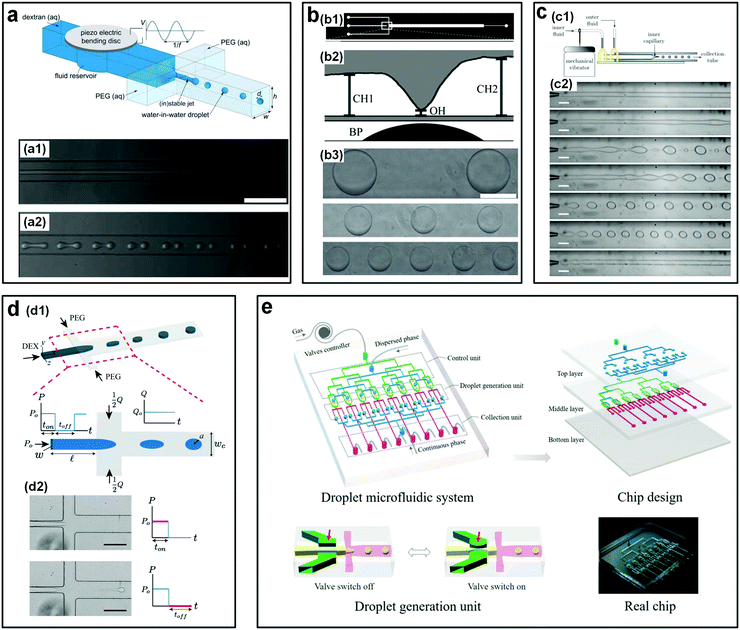 | ||
| Fig. 6 Mechanical actuations to accelerate the breakup of w/w jets. (a) Perturbations from a piezo-electric bending disc. Top: Schematic of the microfluidic device. Bottom: Experimental images showing the jets (a1) without any piezo-electric actuations and (a2) with a piezo-electric actuation at a frequency of 20 Hz and an amplitude of 3 V, both of (a1) and (a2) are captured at 5 mm downstream. Scale bars are 250 μm. Reproduced with permission.49 Copyright 2011, Royal Society of Chemistry. (b) Perturbations from a pin actuator: (b1) Diagram of the photomask for the microfluidic fabrication. (b2) Schematic showing the side view of the microfluidic device where a Braille pin (BP) is integrated into the channels to actuate the valve. (b3) Microscope images of resulting droplets with valve frequencies of 2.5 Hz, 1.25 Hz, and 0.8333 Hz from top to bottom, respectively. The scale bar is 200 μm. Reproduced with permission.50 Copyright 2011, Royal Society of Chemistry. (c) Perturbations from a mechanical vibrator that forces the inlet tubing: (c1) Schematic of the experimental setup. (c2) Optical images of resulting jets or droplets with vibration frequencies of 0 Hz, 3 Hz, 4 Hz, 6 Hz, 7 Hz, 8 Hz, and 10 Hz from top to bottom, respectively. Scale bars are 200 μm. Reproduced with permission.51 Copyright 2012, AIP Publishing. (d) Perturbations from a solenoid valve that pulsates the inlet pressure: (d1) Schematic of the experimental setup. (d2) Experimental images showing the breakup of jets into droplets controlled by the on–off cycle of the pressure. Scale bars are 200 μm. Reproduced with permission.52 Copyright 2015, Royal Society of Chemistry. (e) A pneumatic valve controlling the dispersed phase, where parallel units are assembled into the microfluidic device. Reproduced with permission.48 Copyright 2018, WILEY-VCH. | ||
Besides the integration of piezo-electric disc and Braille pin, an easy and low-cost strategy that also enables controllable generation of w/w droplets would be to connect an additional perturbation unit to existing microfluidic devices without modifications.31,51 For instance, a mechanical vibrator controlled by an external generator is directly connected to a droplet making device and perturbs the inlet pressure of the dispersed fluids via the tubing of dispersed solutions. By adjusting the frequency of the vibrator, uniform droplets with a small amount of satellite droplets can be produced (Fig. 6c). In another work, droplet formation is achieved by pulsating the inlet pressure using a commercial pressure-controlled syringe pump.52 The droplet phase is regulated by a square-wave pulsating pressure with on–off cycles controlled by a pneumatic solenoid valve, while the continuous phase flows through the cross channels (Fig. 6d). With this method, uniform droplets with tunable size and generation rate are achieved by controlling the frequency of on–off cycles and the flow rate of the continuous phase. For the above two strategies, no additional components need to be integrated into the droplet-making device, significantly simplifying the fabrication of devices.
Assembly of microchannels into a single microfluidic device can largely improve the generation rate of w/w droplets. For instance, a novel high-throughput microfluidic platform that can be used to controllably generate large amounts of monodisperse w/w droplets is designed.48 The microfluidic platform is made up of three parts, including a control unit that is to drive solenoid valves, a droplet generation unit that is to generate droplets, and a collection unit that is to collect emulsion droplets, respectively. The microfluidic channels are formed by bonding three pieces of PDMS. During experiments, the droplet and continuous phases are pumped from the inlets of the top layer and are evenly distributed into eight separated channels. After flowing into the middle PDMS layer, the pneumatic valves that are integrated into the channels control the generation of w/w droplets via switching the valves off and on (Fig. 6e). The droplet size can be precisely controlled via adjusting the flow rates of two aqueous phases and the on–off cycle of the valve. The droplet generation rate can be as high as 100 Hz in the 8-channel microfluidic device.
Apart from mechanical actuations, other external triggers, such as the electrohydrodynamic (EHD) perturbation, have also been used to accelerate the breakup of w/w jets.53 For instance, a DC electric field is introduced into a microchannel to trigger the splitting of droplets from a main w/w jet (Fig. 7a). To achieve droplet fission from the main jet, two incompatible solutes that form the ATPS typically need to have different electrophoretic mobility, such as tetrabutylammonium bromide (TBAB) and ammonium sulfate (AS). However, the generation rate of w/w droplets with this active approach is only around 5 drops per second.53,55 In addition, the requirement of two aqueous phases having different electrophoretic mobilities largely limits the potential of this technique. To increase the ability and generality of droplet generation induced by the electric force, the conventional electrospray technique has been incorporated into the microfluidic device.54 In a typical experiment, the droplet-forming phase and the continuous phase are initially separated by air, where the high surface tension between the aqueous phase and air greatly favors the droplet breakup. Upon formation, the droplets can directly fall into the bottom continuous phase (Fig. 7b). By further applying and adjusting the electric voltage between the droplet and substrate phases, the size of the resulting droplets can be reduced and further controlled. With this approach, the fabricated droplet size spans a very wide range, from 45 μm to 2000 μm. This all-aqueous electrospray (AAE) technique avoids the direct contact of two aqueous phases before droplet formation, bypassing the challenge brought by the ultralow interfacial tension of aqueous–aqueous interfaces and showing great potential for fabricating w/w emulsion droplets.
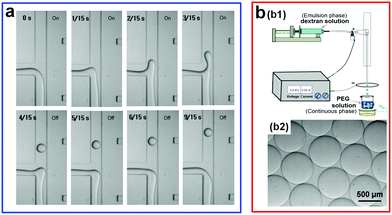 | ||
| Fig. 7 Electrical actuations applied to accelerate the breakup of w/w jets. (a) Electrohydrodynamic (EHD) chopping. The channel width is 200 μm. Reproduced with permission.53 Copyright 2007, Elsevier. (b) All-aqueous electrospray (AAE): (b1) Schematic showing the AAE platform. (b2) The microscope image of the resulting w/w droplets with an applied voltage U = 2.67 kV. Reproduced with permission.54 Copyright 2015, American Chemical Society. | ||
There also exist some other novel passive/active strategies that can largely enhance the droplet generation rate. For instance, a very simple way to rapidly emulsify w/w droplets is to introduce an “oil-droplet chopper” into the microfluidic channels.56 The fast breakup of o/w jets due to their high interfacial tensions spontaneously induces the breakup of low-tension w/w jets (Fig. 8a). In particular, in the synchronization regime where the two events of breakup happen simultaneously, a high uniformity (CV: 0.75–2.45%), a wide range (radius: 5–180 μm), and a particularly high generation rate (∼2100 Hz) of w/w droplets can be achieved. In a separate work, an interfacial fingering-rupture strategy is introduced to rapidly generate very small-sized w/w emulsion droplets.57 By applying sound-induced vibrations into co-flowing streams of an ATPS in a glass capillary-based microfluidic device, liquid micro-fingers, which may be induced by wall wettability58 or viscous instability,59 are generated at the interface of an expanding jet (Fig. 8b). However, the protruded fingers are unstable and spontaneously breakup into small droplets due to RP instability. The droplet generation rate can be adjusted by varying the vibration frequency, typically ranging from a hundred Hz to a thousand Hz. Remarkably, with this strategy, the diameter of fabricated droplets is not limited by the nozzle diameter of inner channels, and can be several times smaller than the diameter of the nozzle. In a typical case, the generated droplets can be as small as 3 μm, one order of magnitude smaller than the nozzle size (tens of micrometers).57
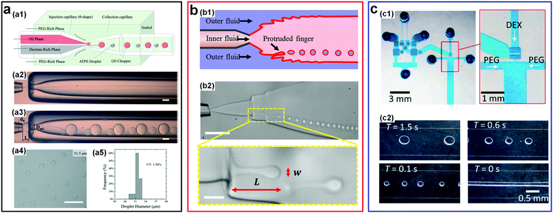 | ||
| Fig. 8 Other typical passive/active strategies including oil choppers, interfacial fingers, and microfluidic oscillators to accelerate the breakup of w/w jets. (a) W/w jets chopped by oil droplets: (a1) Schematic of the microfluidic device. (a2) The optical microscope image of the stable jet formed in the absence of oil-choppers. (a3) The optical microscope image of the jet breaking into droplets in the presence of oil-choppers. (a4 and a5) A typical image and the size distribution of resulting droplets. Scale bars are 200 μm. Reproduced with permission.56 Copyright 2017, Royal Society of Chemistry. (b) Breakup of vibration-induced interfacial fingers: (b1) Schematic of the experimental setup. (b2) Optical microscope images showing the formation process of the droplets. Scale bars are 100 μm and 20 μm for low and high magnifications, respectively. Reproduced with permission.57 Copyright 2018, American Chemical Society. (c) Water-head-driven microfluidic oscillator: (c1) Images of the integrated oscillator and valve. (c2) Images of the resulting droplets, where without any actuations (T = 0 s), a stable jet forms. Reproduced with permission.60 Copyright 2017, Royal Society of Chemistry. | ||
Another interesting design to generate w/w droplets is based on the water-head-driven microfluidic circuits and this design does not involve any dynamic off-chip controllers (Fig. 8c).60 Using a microfluidic oscillator, flow-switching period (T) and flow rate (Q) are regulated across a very wide operating range in which 0.1 s < T < 5.9 h and 2 μL min−1 < Q < 2 mL min−1. The successful generation of w/w emulsion droplets in a controllable way shows the potential of the designed oscillator in emulsifying droplets with low interfacial tensions. W/w droplets can also be formed by membrane emulsification.61,62 For instance, a porous hollow-fiber can be introduced to emulsify w/w droplets.61 In addition, the size of the resulting droplets can be further reduced by utilizing the “non-equilibrium” ATPSs, where an osmolality difference is present between the two aqueous phases and water can be gradually extracted from the droplets.63 Using this approach, highly uniform w/w droplets with polydispersity less than 1% can be achieved.61 The ability to control generation of w/w emulsion droplets in microchannels is a prerequisite to their use as templates to fabricate some highly biocompatible materials. The existing strategies to fabricate w/w emulsion droplets in microchannels from the literature are summarized in Table 1.47,56
| List of methods | Diameter (μm) | Coefficient of variation (CV, %) | Generation rate (Hz) | ATPSs (average Mw if available) | Ref. |
|---|---|---|---|---|---|
| Passive methods | |||||
| (a) Weak hydrostatic pressure | ∼10–110 | <1 (dripping) | ∼15 (1 channel) | PEG (35 kDa) + DEX (500 kDa) | 30, 42 and 72–74 |
| ∼10 (jetting) | ∼50 (4 channels) | ||||
| (b) Flow rate controlled | 14–28 | — | 300 | PEG (35 kDa) + DEX (500 kDa) | 44 |
| (c) Microneedle-assisted flow focusing | ∼5–65 | ∼10 | 850 | PEG (35 kDa) + DEX (500 kDa) | 47 |
| (d) Oil-droplet chopper | 10–360 | 0.75–2.45 | 2100 | PEG (8 kDa) + DEX (40 kDa) | 56 and 75 |
| (e) Variable-width microchannel | 10–100 | 5–20 | 20 | PEG (35 kDa) + DEX (500 kDa) | 76 |
| (f) Assembled evaporation pump | 44–93 | 3.2 | ∼60 (8 units) | PEG (20 kDa, 500 kDa) + DEX (40 kDa, 100 kDa, 500 kDa) | 77 |
| (g) Membrane emulsification (porous hollow-fibers) | ∼500–1200 | <1 | — | PEG (4 kDa) + K2HPO4 | 61 |
| (h) Membrane emulsification (Shirasu porous glass membranes) | 6–50 | ∼10 | — | PEG (8 kDa) + DEX (15–20 kDa) | 62 |
| Active methods | |||||
| (1) Mechanical and acoustic actuations | |||||
| (a) Piezoelectric disk | 30–60 | — | ∼50 | PEG (35 kDa) + DEX (110 kDa) | 23 and 49 |
| (b) Pin actuator | ∼0.9–3.4 nL | — | ∼2.5 | PEG (35 kDa) + DEX (500 kDa) | 50 |
| (c) Mechanical vibrator | ∼20–100 | <4 | ∼30 | PEG (8 kDa), PEGDA + DEX (500 kDa), K3PO4, K2HPO4 | 22, 51 and 78 |
| (d) Solenoid valve (inner phase) | 44–354 | — | ∼5 | PEG (8 kDa) + DEX (100 kDa) | 52 |
| (e) Solenoid valve (shell phase) | ∼200–400 | — | ∼3 | PEG (10 kDa) + DEX | 79 |
| (f) Pneumatic valve | ∼50–100 | 2.58–2.98 | ∼13 (1 channel) | PEG (8 kDa, 20 kDa) + DEX (70 kDa, 500 kDa) | 48 |
| 3.5 | ∼100 (8 channels) | ||||
| (g) Mechanical vibrator (rupture of interfacial fingers) | 3–17 | ∼3 | 1000 | PEG (4 kDa, 8 kDa) + sodium citrate dehydrate, K3PO4, Na2CO3, DEX (500 kDa) | 57 |
| (h) Microfluidic oscillator | ∼200–400 | — | — | PEG (35 kDa) + DEX (550 kDa) | 60 |
| (i) Audio speaker | 100–250 | — | ∼60 | PEG (8 kDa) + DEX (550 kDa) | 80 |
| (2) Electrical actuations | |||||
| (a) Electrohydrodynamic (EHD) perturbation | — | — | ∼5 | Tetrabutylammonium bromide (TBAB, 322.38 Da) + ammonium sulfate (AS, 132.14 Da) | 53, 55, 81 and 82 |
| (b) All-aqueous electrospray (AAE) | ∼45–2000 | 3.6–6.7 | — | PEG (20 kDa) + DEX (500 kDa) | 54 |
3.2 Fabrication of all-aqueous complex emulsion droplets
Complex emulsion droplets can encapsulate active ingredients and release them when triggered, making them of particular interest to pharmaceuticals and food industries.38,64 All-aqueous complex droplets, such as water-in-water-in-water (w/w/w) double emulsion droplets can also encapsulate biomolecules, and with the additional advantage of high preservation of activity. To form monodisperse w/w/w double emulsion droplets, multiple small-radii glass capillaries can be assembled into a single microfluidic device. In addition, external perturbations such as mechanical vibration can also be imposed to enhance the jet breakup (Fig. 9a).51 In this way, the all-aqueous double emulsion droplets are achieved in two steps. However, the manual assembly of additional capillary glasses into a microfluidic device makes the fabrication process very complicated and time-consuming. To avoid such sophisticated steps, an alternative facile strategy is to take advantage of spontaneous phase separation inside non-equilibrium single-layered w/w droplets to achieve all-aqueous multi-layered emulsion droplets (Fig. 9b and c).65,66 With this approach, w/w/w double emulsion droplets can be emulsified within one-step in the same device that is applied for generation of w/w single emulsion droplets. For instance, perturbation-induced monodisperse droplets made up of 5% DEX (Mw = 500 kDa) are initially produced into a concentrated PEG continuous phase. Because of the high osmolality of the outer PEG phase, water is gradually extracted from the droplets, increasing the solute concentration. As the PEG and DEX concentrations inside the droplets increase above critical values, spontaneous phase separation is triggered and w/w/w double emulsion droplets form (Fig. 9c). Highly monodisperse double droplets with an excellent polydispersity of less than 4% have been achieved with this method.66 In particular, with this phase separation approach, even higher-order, such as triple and quadruple, all-aqueous emulsion droplets can be formed if the concentrations of two solutes in the initial single-layered droplet are chosen near the vertex of the binodal curve (Fig. 9d).67 This strategy can also be applied to form other types of all-aqueous complex droplets, such as all-aqueous Janus droplets. By varying the mass ratio of two incompatible solutes in single-layered droplet templates, all-aqueous Janus droplets with different morphologies can be produced controllably (Fig. 9e).68,69 Other similar strategies, such as evaporation-induced phase separation, can also help formation of all-aqueous double and Janus emulsion droplets.70,71 Furthermore, batch methods to produce reverse Janus-type and yolk–shell-shaped all-aqueous complex emulsion droplets can be achieved via one-step mixing83 and temperature-variation-induced phase separation,84 respectively. These studies show the interest and ability of liquid–liquid phase-separation (LLPS) of ATPSs in producing all-aqueous complex emulsion droplets.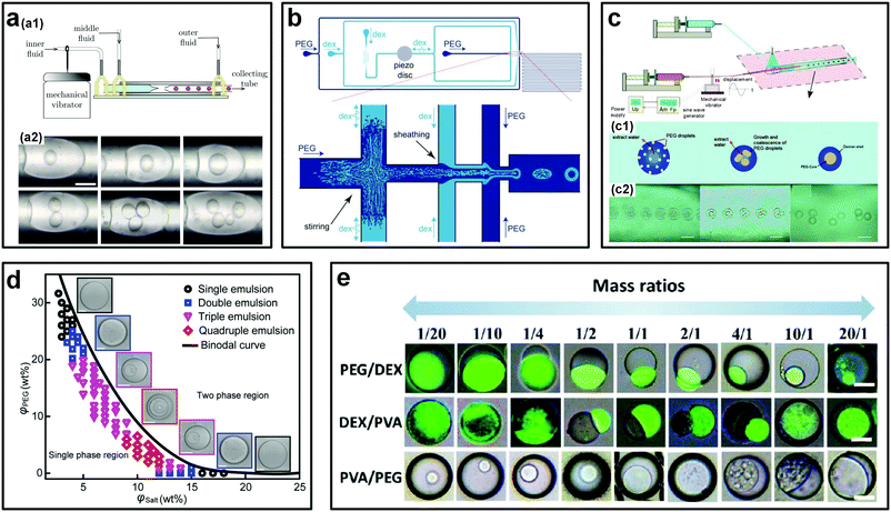 | ||
| Fig. 9 Strategies to generate all-aqueous complex emulsion droplets. (a) The assembled microfluidic device for forced formation of w/w/w double emulsions droplets: (a1) Schematic of the experimental setup. (a2) Optical images showing the formed double emulsion droplets with different sizes of and with different numbers of the inner droplets. The scale bar is 100 μm. Reproduced with permission.51 Copyright 2012, AIP Publishing. (b) Schematic showing the PDMS-based microfluidic device for the forced formation of w/w/w double emulsions driven by phase separation. Reproduced with permission.65 Copyright 2011, Royal Society of Chemistry. (c) The glass capillary-based microfluidic device for the forced formation of w/w/w double emulsions driven by phase separation: (c1) Schematic showing the formation process. (c2) Typical experimental sequences. Scale bars are 100 μm. Reproduced with permission.66 Copyright 2012, American Chemical Society. (d) Phase diagram showing the phase-separation-induced formation of different order all-aqueous emulsion droplets. Scale bars are 200 μm. Reproduced with permission.67 Copyright 2018, WILEY-VCH. (e) Phase-separation-induced formation of all-aqueous Janus droplets from different ATPSs. Scale bars are 50 μm. Reproduced with permission.68 Copyright 2017, American Chemical Society. | ||
3.3 Stabilization of all-aqueous emulsion droplets
The successful generation of all-aqueous emulsion droplets provides a great opportunity to utilize these oil-free and biocompatible droplets in various applications, such as stable biological hosts, reactors, and templates in synthesis of biomaterials.85 However, the stabilization of these all-aqueous droplets remains challenging, although the stabilization of their counterparts, o/w or w/o emulsion droplets, has been realized for a long time.86 The challenges against stabilizing w/w emulsion droplets mainly stem from two fundamental properties related to the w/w interface, including: (i) A large thickness, and (ii) an ultralow interfacial tension.The thickness of the w/w interface is theoretically calculated to be from tens of nanometers87 to a few hundred nanometers88 (Fig. 10a and b). Therefore, a surfactant molecule with a typical length of several nanometers, which is large enough to settle at the o/w interface,86 may not settle at the thick w/w interface. This incapability of settlement may explain why small molecules fail to stabilize w/w emulsion droplets. Another challenge is with respect to stabilization by colloidal particles, which are widely applied to stabilize o/w emulsion droplets, known as the Pickering effect.89,90 Thermodynamically, adsorption of colloidal particles onto the liquid–liquid interface reduces the total free energy, prevents the direct contact of neighboring droplets, and thus provides an excellent barrier against droplet coalescence. However, due to the ultralow interfacial tension of the w/w interface (Fig. 10c and d), the maximum adsorption energy, given by γA (γ and A are the interfacial tension of the w/w interface and the cross-sectional area of the particle, respectively), is several orders of magnitude smaller than that for the o/w interface with adsorbed particles. This low adsorption energy results in a very weak driving force for colloids to adsorb onto the w/w interface, particularly when both the particle size and interfacial tension are very small. The reduction of the interfacial energy (ΔG) by the adsorption of a spherical particle at the droplet surface is given by91
ΔG(sphere) = −(π/4)d2γ(1 − |cos![[thin space (1/6-em)]](https://www.rsc.org/images/entities/char_2009.gif) θ|)2 θ|)2 | (4) |
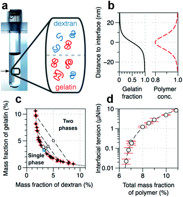 | ||
| Fig. 10 Physicochemical properties of the w/w interface. (a) A typical image of a phase-separated ATPS consisting of DEX and gelatin. The tube width is 1.2 cm. (Inset) Schematic showing the spatial distribution of DEX and gelatin near the w/w interface. (b) The gelation fraction and the relative total concentration of polymers calculated from theory.92 (c) Phase diagram based on the mass fraction of two solutes. (d) The dependence of interfacial tension on the total mass fraction of polymers. All are reproduced with permission.87 Copyright 2015, American Chemical Society. | ||
To realize the interfacial stabilization of w/w emulsion droplets, several strategies have been proposed, such as synthesizing customized macromolecular surfactants,93 and adopting different kinds of colloidal particles.94 In addition to the macromolecular and particle surfactants, directly transferring droplets into microcapsules, such as via the complexation of oppositely charged polyelectrolytes (PEs) at w/w interfaces, is another alternative way to stabilize w/w emulsion droplets.95
3.3.1 Block copolymers
Designing block polymers with comparable sizes to the width of w/w interfaces represents a new route towards stabilizing w/w emulsion droplets.93,96 For instance, ABC triblock polymers have been designed as macromolecular surfactants to stabilize w/w emulsion droplets of the PEG–DEX ATPS.97 The amphiphilic triblock copolymers are made up of the poly[(ethylene glycol)methyl ether methacrylate] (PEGMA), poly(n-butyl methacrylate) (BuMA), and poly[2-(dimethylamino)ethyl methacrylate] (DMAEMA) blocks. The middle block (BuMA) is hydrophobic, whereas the two ends, PEGMA and DMAEMA, are hydrophilic and have preferable affinities towards PEG and DEX aqueous phases respectively (Fig. 11a). Consequently, the designed triblock polymers are long enough to settle at the thick w/w interface, and w/w emulsion droplets with average size from 5 μm to 100 μm in diameter can be stabilized for as long as 6 months (Fig. 11b). However, the fabrication of this kind of surfactant involves complicated synthetic steps such as synthesis of the polymerization catalyst, tetrabutylammonium bibenzoate (TBABB), as well as many organic solvents such as n-hexane, tetrabutylammonium hydroxide, and benzoic acid.97 Therefore, a more facile way to design block copolymers with less reliance on organic solvents is also important for stabilization of w/w emulsion droplets.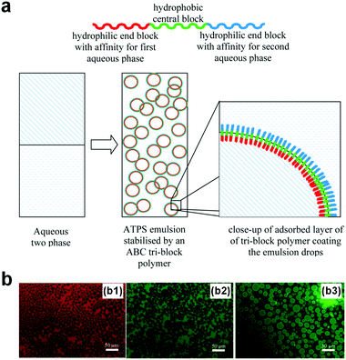 | ||
| Fig. 11 W/w emulsion droplets stabilized by the designed block polymers. (a) The design of the ABC-type copolymer. (b) Fluorescence microscope images showing w/w emulsion droplets stabilized by the copolymers with a concentration of 1.0 wt% that contains different dyes, including (b1) rhodamine, (b2) fluorescein, and (b3) FITC–dextran conjugate. Reproduced with permission.97 Copyright 2013, American Chemical Society. | ||
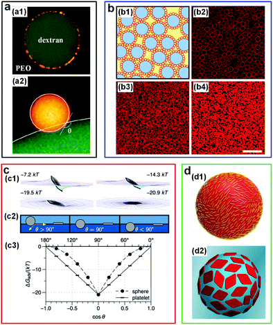 | ||
| Fig. 12 W/w emulsion droplets stabilized by colloidal particles. (a) CLSM images showing the position of latex particles at the w/w interface: (a1) A DEX-rich droplet adsorbed by latex particles (yellow) in PEO-rich solutions. The particle radius is 0.25 μm. (a2) A close-up view showing the contact angle of a latex particle (radius: 1 μm, yellow) at the w/w interface. Reproduced with permission.100 Copyright 2012, American Chemical Society. (b) Liposome-stabilized DEX-rich droplets dispersed in the PEG-rich continuous phase: (b1) Schematic of stabilized droplets (red: Liposomes; blue: DEX-rich phase; yellow: PEG-rich phase). (b2–b4) Fluorescence microscope images showing the stabilized droplets with different liposome concentrations: (b2) 0.14 × 10¹⁶, (b3) 0.34 × 10¹⁶, and (b4) 1.0 × 10¹⁶ liposomes per liter. Scale bar is 25 μm. Reproduced with permission.101 Copyright 2014, Nature Publishing Group. (c) Numerical results showing the adsorption energy of a nanoplate (effective diameter: 167 nm) at the w/w interface with an interfacial tension of 4 μN m−1: (c1) The adsorption energy of the nanoplate orienting in various configurations. (c2) Schematic showing the contact angle of particles with two different shapes: Spheres and platelets. (c3) The dependence of adsorption energy (ΔGabs) for spheres and platelets on the contact angle (θ). Reproduced with permission.87 Copyright 2015, American Chemical Society. (d) Schematics showing the w/w droplets stabilized by colloidal particles with different morphologies: (d1) Cellulose nanocrystals (CNCs). Reproduced with permission.102 Copyright 2016, American Chemical Society. (d2) Two-dimensional polymer platelets. Reproduced with permission.103 Copyright 2017, American Chemical Society. | ||
Protein microgel particles have also been applied to prevent coalescence of w/w droplets.106–108 The pH sensitivity of some of these microgels can be used to control the stability of w/w emulsion droplets via simply adjusting the pH value. For instance, long-term stability (over one week) of w/w emulsion droplets from a PEG–DEX ATPS can be achieved by utilizing pH-sensitive microgels (60–220 nm) with a pH value in the range of 7–7.5.109 Besides pH, this work also shows that, even after adjusting the pH to the optimum window, the concentration of salts also significantly affects stability: Increasing salt concentration accelerates destabilization. Another work also shows the effect of pH on the stabilization of w/w emulsion droplets in a different ATPS of amylopectin (AMP) and xyloglucan (XG), where w/w droplets can be stabilized when pH ≤ 5. The stabilization is enabled by the surface modification of the particles by adsorption of XG on the particle surface when pH is less than 5.5.107 These pH-controlled w/w Pickering emulsions have great potential in some applications that require a controllable release process.
However, almost all of the above-mentioned studies focus on understanding the stabilization ability of spherical particles on polymer/polymer-based w/w emulsion droplets (Fig. 12a and b). In fact, the presence of two polymers makes the understanding of particle behaviors in two aqueous phases more complicated, due to the potential adorption of both polymers at the particle surfaces. To simplify the system, polymer/salt ATPSs can be adopted instead. Using the PEG (Mw = 8 kDa)/Na2SO4 ATPS, the stabilizing effects of various particles, including hydrophilic calcium carbonate particles, wax particles, and dichlorodimethylsilane modified silica particles, have been studied. Among them, the addition of dichlorodimethylsilane modified silica particles that possess partial hydrophobicity shows an excellent stabilizing effect, which can stabilize w/w emulsion droplets for one year.110 The mechanism of how the wettability of polymer or salt solutions on particle surfaces affects the w/w emulsion stability still requires a systematical study in the future.
Apart from the w/w emulsion droplets stabilized by spherical particles, the stabilization of these droplets by non-spherical particles has also been explored. For instance, the effect of ultrathin sub-micrometer nanoplates on the interfacial stabilization of w/w emulsions has been investigated both theoretically and experimentally. Based on numerical calculations, the adsorption of plate-like particles onto the w/w interface is significantly stronger than that of spherical particles with identically maximal cross-section (apart from when the contact angle is 90°) (Fig. 12c).87 This theoretical prediction is further verified experimentally by using gibbsite nanoplates with a radius of 170 nm and a thickness of 7 nm as a model system, where the w/w emulsions of DEX and nongelling fish gelatin can be stabilized for several weeks. In addition, the low buoyant mass of the 2D nanoplates presumably helps reduce the sedimentation of emulsion droplets (creaming) when the mass density between the particles and solutions differs significantly.87
One-dimensional nanorods in the form of cellulose nanocrystals (CNCs) have also been demonstrated to stabilize w/w emulsion droplets.102 CLSM and static light scattering (SLS) techniques are used to determine the coverage of CNCs on the droplet surface. It is assumed that these highly anisotropic nanorods with mean dimensions of 160 nm × 6 nm × 6 nm lie on the droplet surface in parallel, showing a similar configuration of CNC observed in o/w systems to prevent droplet coalescence (Fig. 12d1). However, only the DEX-in-PEO emulsion droplets are stabilized, probably due to the preferred partitioning of CNC into the DEX-rich phase compared to that in the PEO-rich phase. In addition, protein nanofibrils can also be used to stabilize droplets by controllable layer-by-layer growth of the nanofibril-networks at w/w interfaces.113
Another striking strategy is to design 2D poly(lactide) platelets of controllable surface and of uniform chemical composition and thickness (Fig. 12d2).103 This work indicates that platelets with high surface areas have better stabilizing effects than those with low surface areas, and the same trend is also found for w/w emulsion droplets stabilized by platelets with modified coronal chemistries. This difference is supposed to be attributed to the different adsorption energies and rotation barriers of the platelets. The ability of designed 2D poly(lactide) platelets to stabilize w/w emulsions inspires the modification of the surface properties of particles rather than the shape and size of particles, to realize stable w/w emulsion droplets.
The stabilization of w/w Pickering emulsion droplets can be further enhanced by crosslinking. For instance, particle-stabilized w/w emulsion droplets have been achieved by crosslinking polydopamine nanparticles (PDP) via poly(acrylic acid) (PAA) and 1-ethyl-3-(3-dimethylaminopropyl)carbodiimide (EDC) (Fig. 13a).111 The crosslinking significantly strengthens the stability of the droplets in the form of a colloidosome-like structure, where the de-emulsification due to dilution or surfactant addition can be greatly hindered. In another work, stable gelled w/w droplets are achieved by adding PAA/DEX and then by crosslinking fluorescent amine-modified polystyrene latex beads (LBs) with DEX at the interface.112 Through controlling the electrostatic interactions and the swelling properties, the gelled droplets can swell reversibly and take up/exclude molecules selectively (Fig. 13b), suggesting a new route to control the stability of these emulsion droplets. Other types of colloidal particles have also been used to explore the stability effect of w/w emulsion droplets, such as polymer–protein conjugates,114 as summarized chronologically in Table 2.94 These advances in stabilizing w/w emulsion droplets by colloidal particles are expected to inspire and enable more applications that require stable all-aqueous emulsion droplets, such as interfacial catalysis of bioactive protein particles at the stabilized w/w interface.114
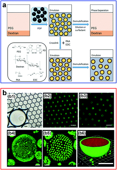 | ||
| Fig. 13 W/w emulsion droplets stabilized by particles and crosslinking. (a) An overview of w/w emulsion droplets stabilized by polydopamine particles (PDP) and crosslinking with poly(acrylic acid) (PAA)/1-ethyl-3-(3-dimethylaminopropyl)carbodiimide (EDC). Reproduced with permission.111 Copyright 2018, American Chemical Society. (b) Stable hydrogel-containing w/w emulsion droplets: (b1 and b2) White-light and epifluorescence images of 40 pL w/w emulsion droplets containing single hydrogelled colloidosomes. (b3) The epifluorescence image after picoinjection of water (3-fold dilution). (b4 and b5) CLSM images of gelled droplets using latex beads with a diameter of 1 mm in relaxed (iv) and swelled (v) forms. The scale bar is 5 μm. (b6) CLSM image showing the relaxed hydrogel-containing microdroplets that take up florescence molecules (scale bar: 5 μm). Reproduced with permission.112 Copyright 2018, Wiley-VCH. | ||
| Year | Particle type | ATPSs (average Mw if available) | Ref. |
|---|---|---|---|
| 2008 | Fat, quartz, whey protein particles, mono-glycerides, probiotics | Methylcellulose + DEX, maltodextrine 6DE + DEX, whey proteinconcentrate + methylcellulose | 98 |
| 2009 | Amphoteric polystyrene latex | Gelatin + oxidized starch | 99 |
| 2012 | Latex, β-lactoglobulin protein particles | Poly(ethylene oxide) (PEO, 200 kDa) + DEX (500 kDa) | 100 |
| 2013 | β-Lactoglobulin protein particles | PEO (200 kDa) + DEX (500 kDa) | 106 |
| 2013 | Oil droplets | Sodium caseinate + xanthan | 116 |
| 2014 | Silica nanoparticles | Starch + locust bean gum | 117 |
| 2014 | Oil droplets | Sodium caseinate + xanthan | 118 |
| 2014 | Single-celled microorganisms | Gelatin + maltodextrin | 119 |
| 2014 | PEGylated liposomes | PEG (8 kDa) + DEX (10 kDa) | 101 |
| 2015 | Microgel particles | PEO (200 kDa) + DEX (500 kDa) | 109 |
| 2015 | Lipid vesicles | PEG (8 kDa) + DEX (10 kDa) | 120 |
| 2015 | Gibbsite nanoplates | Gelatin (100 kDa) + DEX (100 kDa) | 87 |
| 2015 | Living bacteria (Escherichia coli and Pseudomonas aeruginosa) | Casein + xanthan | 121 |
| 2016 | β-Lactoglobulin protein particles (fibrils, microgels, fractal aggregates) | PEO (200 kDa) + DEX (160 kDa) | 122 |
| 2016 | β-Lactoglobulin protein particles | Amylopectin (1.3 × 10⁷ Da) + xyloglucan (2.9 × 10⁶ Da) | 107 |
| 2016 | Cellulose nanocrystals | PEO (200 kDa) + DEX (500 kDa) | 102 |
| 2016 | Whey protein microgels | Starch + locust bean gum | 108 |
| 2016 | Amyloid nanofibrils | PEG (20 kDa) + DEX (500 kDa) | 113 |
| 2017 | Methoxy polyethylene glycol (mPEG)–urease conjugate particles | PEG (8 kDa) + DEX (500 kDa) | 114 |
| 2017 | Zein particles | Gelatin (100 kDa) + DEX (450–650 kDa) | 104 |
| 2017 | β-Lactoglobulin protein particles | PEO (200 kDa) + DEX (500 kDa) | 123 |
| 2017 | Montmorillonite platelets | PEO (100 kDa) + pullulan (90 kDa) | 124 |
| 2017 | Natural clay particles | PEG (8 kDa) + DEX (10 kDa) | 125 |
| 2017 | Carboxylated particles | PEG (35 kDa) + DEX (500 kDa) | 126 |
| 2018 | Poly(lactide) platelets | PEO (200 kDa) + DEX (500 kDa) | 103 |
| 2018 | Cellulose nanocrystals | PEO (200 kDa) + DEX (500 kDa) | 127 |
| 2018 | Amine-modified polystyrene latex beads | PEG (20 kDa) + DEX (2000 kDa) | 112 |
| 2018 | Zein/pectin particles | Waxy corn starch + guar gum | 128 |
| 2018 | Nylon beads | PEG (20 kDa) + Ficoll (400 kDa) | 129 |
| PEG (8 kDa) + DEX (500 kDa) | |||
| 2018 | Silica nanoparticles | PEG (20 kDa) + MgSO4 | 130 |
| 2019 | Dichlorodimethylsilane modified silica particles | PEG (8 kDa) + Na2SO4 | 110 |
| 2019 | Whey protein particles | PEO (200 kDa) + DEX (500 kDa) | 131 |
| 2019 | Polydopamine particles | PEG (20 kDa, 35 kDa, 40 kDa) + DEX (40 kDa, 100 kDa) | 111 and 132 |
| 2019 | CaCO3 particles | PEG (8 kDa) + DEX (500 kDa) | 133 |
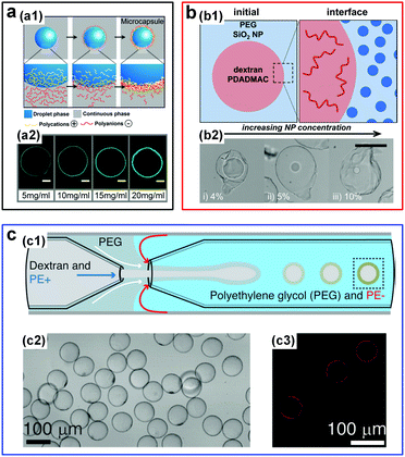 | ||
| Fig. 14 W/w emulsion droplets stabilized by the interfacial complexation. (a) Fabrication of microcapsules via complexation of oppositely charged polyelectrolytes (PEs): (a1) Schematic showing the fabrication process. (a2) CLSM images of resulting PE shells with different thicknesses for different concentrations of PSS and FITC-PAH. Scale bars are 50 μm. Reproduced with permission.115 Copyright 2016, American Chemical Society. (b) Fabrication of microcapsules via complexation of oppositely charged PEs and nanoparticles (NPs): (b1) Initial locations of NPs and PEs in the two aqueous phases. (b2) Optical images of microcapsules fabricated from NPs with concentrations of (i) 4%, (ii) 5%, and (iii) 10%. The scale bar is 100 μm. Reproduced with permission.134 Copyright 2017, American Chemical Society. (c) Fabrication of PE capsules from w/w droplets prepared in a glass capillary microfluidic device: (c1) Schematic of the microfluidic channels. (c2 and c3) Optical microscope and CLSM images of formed capsules, respectively. Reproduced with permission.135 Copyright 2016, Wiley-VCH. | ||
Additional control has been demonstrated in forming PE microcapsules in one step by inducing interfacial complexation of oppositely charged PEs in microfluidic droplets.135 In particular, a transient middle aqueous phase needs to be introduced to prevent the clogging of the microfluidic channels by the complexed PEs (Fig. 14c). Interfacial complexation at w/w interfaces is highly general and can be achieved using even more complex PEs, such as intracellular polymers like proteins and DNA strands,136 as well as charged polysaccharides and microparticles like k-carrageenan/chitosan and protein microgels.137 Interfacial complexation to stabilize w/w emulsion droplets and form capsules will play an important role in all-aqueous based encapsulation applications, by allowing construction of highly stable complex structures.
4. Biomedical applications of ATPSs
4.1 Design of artificial cells and cyto-mimetic materials
The ability to construct simplified and controllable models of highly complex living organisms facilitates the understanding of complex fundamental biological processes138,139 such as the evolution of membraneless organelles. In this context, ATPSs have been used to explore the formation of membraneless organelles through liquid–liquid phase separation (LLPS) in living cells.140,141 The synthetic macromolecule solutions, such as PEG and DEX phases, can be straightforwardly used as model systems to mimic the intracellular environment.18,142 For instance, w/w emulsion droplets encapsulated in lipid membranes have enabled the mimicking of the crowded internal environment and of phase separation in living cells.113,144–146 Micro-compartmentalization of proteins and nucleic acids into aqueous droplet phases relies on the different partitioning of proteins and nucleic acids towards the two immiscible aqueous phases. External stimuli, such as temperature variation, can also affect the phase separation behavior of aqueous polymer solutions, providing a method to control the formation and dissolution of associative phases that are important during the formation of cellular membraneless compartments.147 For instance, the model cytoplasm composed of ATPSs can be easily switched between a single phase and two phases through changing the temperature (Fig. 15a).143 In addition to the temperature-induced spontaneous phase separation, the variation of osmotic pressure can also be used to induce the compartmentalization of proteins and nucleic acids reversibly in these artificial cells.145,146 | ||
| Fig. 15 Design of artificial cells and cyto-mimetic materials within w/w emulsion droplets. (a) W/w droplets encapsulated in lipid vesicles: (a1) Schematic showing the preparation of artificial cells from droplets within lipid vesicles. (a2) The reversible compartmentalization of proteins in lipid vesicles via adjusting the temperature. The scale bar is 10 μm. Reproduced with permission.143 Copyright 2005, National Academy of Sciences of the USA. (b) Liposome-stabilized w/w droplets as micro-reactors for biomimetic mineralization: (b1) Schematic of biomineralization in liposome-coated droplets. (b2) Optical microscope images of mineral formation in droplets of 25 mM EDDS (A) and 22.5 mM EDDS (B). EDDS (thylenediamine disuccinic acid) acts as molecule chelators. The scale bar is 10 μm. Reproduced with permission.120 Copyright 2015, American Chemical Society. (c) Budding-like division in w/w droplets: (c1) Schematic and fluorescence images showing the whole division processes. Scale bars are 100 μm. (c2) Optical images showing the budding of droplets stabilized by protein nanofibrils. Scale bars are 200 μm. Reproduced with permission.150 Copyright 2018, Nature Publishing Group. | ||
ATPS-based compartmentalization can also significantly enhance the reaction rate by increasing local reactant concentrations. For instance, the enhancement of reaction rate is demonstrated in a two-piece ribozyme cleavage reaction within an ATPS of PEG and DEX. Due to the strong partitioning of RNA into the DEX-rich phase, the RNA concentration can be enriched by as high as 3000-fold. This remarkably high RNA concentration gives rise to as high as 70-fold enhancement of ribozyme cleavage rate.148 Furthermore, w/w emulsion droplets stabilized by colloidal particles can also be used as biocompatible micro-reactors to perform some biomimetic reactions. A typical example is that lipid vesicle-stabilized w/w emulsion droplets have been used to realize the artificial mineralization inside these emulsion droplets.120,149 These microdroplet reactors allow the entry of precursors while retaining the protein catalyst inside the droplets due to the different partitioning between two aqueous phases. As a result, CaCO3 deposition is confined inside the DEX-rich droplet phase (Fig. 15b).149 A similar approach has also been applied to perform the ribozyme cleavage reaction inside liposome-stabilized w/w emulsion droplets.101
The budding behavior found in w/w droplets gives a possible explanation for the physical mechanism of protocell division at the early stage. In these ATPS-templated artificial cells, the spontaneous budding-like division can be induced by external stimuli.150–153 For instance, external osmotic pressure can drive the budding in giant vesicles (GVs) with the coexisting aqueous polymer solutions (ATPS GVs).151 Because of the high osmolality in the external solutions, water is gradually drawn away and the initially spherical vesicles that encompass the ATPS become deflated. As the volume of the ATPS GVs decreases, the membrane areas become larger than those required to cover the interior aqueous solutions. As a result, budding helps to minimize the surface energy of interior solutions. In addition, protein nanofibrils can also be utilized to drive the budding-like division of w/w emulsion droplets (Fig. 15c), where the number and size of the “daughter droplets” can be controlled by adjusting the nanofibril concentration as well as the properties of the network.150 Apart from budding, spontaneous tubulation of GVs with a phase-separated ATPS is another striking membrane-associated effect, which begins with the nucleation of small membrane buds and then grows into necklace-like tubes.154,155 The formation of budding and tubulation strongly depends on the droplet size, the membrane tension, the contact angle between the aqueous phase and membrane, as well as the external stimuli such as osmotic pressure.156,157 These studies pave the way for the first evidence that w/w emulsion droplets have great potential as simple models to understand the effect of intracellular compartmentalization in early cells and as a possible way to achieve in vitro biochemical studies.
4.2 Fabrication of biocompatible materials
The excellent biocompatibility of ATPSs means that all-aqueous jets or droplets formed subsequently can be used as templates to fabricate some highly cyto- and bio-compatible materials, such as microfibers22,158 and microparticles.95,159 The microparticles have great potential as advanced biomaterials for a variety of applications, such as in drug delivery, tissue engineering, and cell biology.160,161 In traditional methods that utilize w/o emulsion droplets as templates, the non-aqueous solvents can denature the biomolecules like proteins, and cells encapsulated inside the microparticles. Therefore, to remove the non-aqueous solvents, repeated washing is commonly required after the synthesis of microparticles.162–165 W/w emulsion droplets represent a promising alternative, as they provide all-water environments. As a result, the denaturation of encapsulated elements can be minimized and the washing process can be removed.166 To fabricate these all-aqueous-based microparticles, a wide range of techniques can be applied to transfer the w/w droplet templates into microparticles including (a) photo-polymerization,49,159,166–168 (b) chemical polymerization,48,54,79,169 (c) thermal gelation,54 (d) interfacial complexation,115,134,135,170 and (e) osmo-solidification.171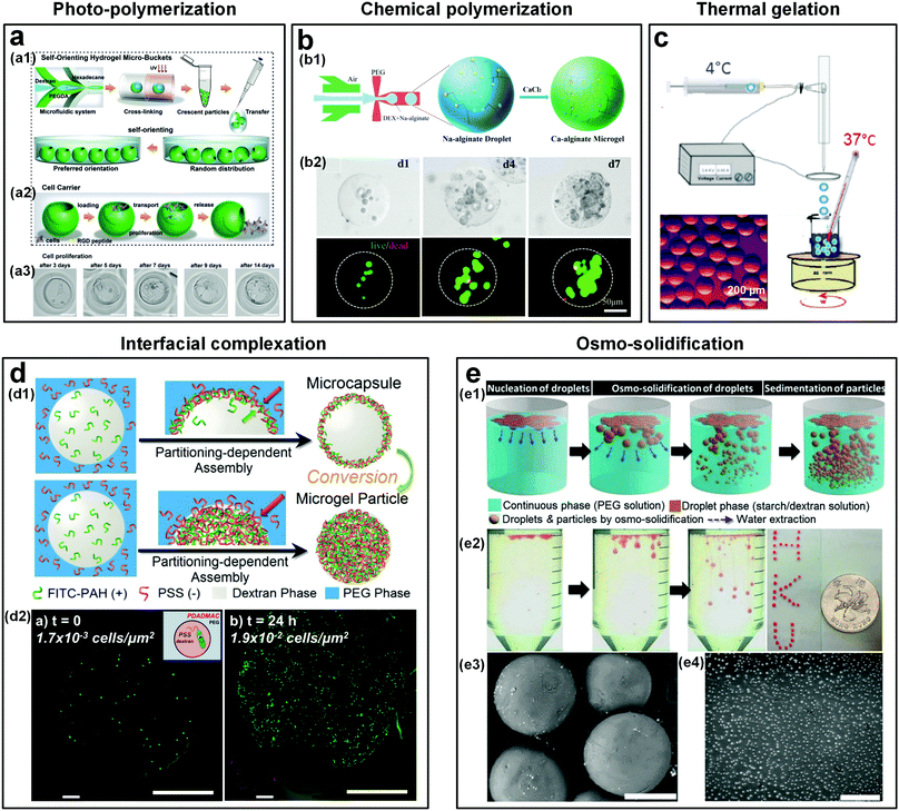 | ||
| Fig. 16 Templated conversion of w/w emulsion droplets into cyto- and bio-compatible microparticles and microcapsules. (a) Crescent-shaped ATPS hydrogel microparticles formed by photo-crosslinking: (a1) Schematic of the microparticle fabrication. (a2) Schematic showing the use of microparticles as cell carriers. (a3) Optical microscope images showing the mouse fibroblast cells in a microparticle after culturing for 14 days. Scale bars are 50 μm. Reproduced with permission.167 Copyright 2019, Wiley-VCH. (b) Microparticles formed by chemical crosslinking: (b1) Schematic showing the formation of alginate-Ca microgels via crosslinking of Na-alginate and CaCl2. (b2) Optical microscope images showing the cells encapsulated in the alginate-Ca microgels after being cultured for 1, 4, and 7 days. Reproduced with permission.48 Copyright 2018, Wiley-VCH. (c) Schematic showing the fabrication of collagen microparticles by thermal gelation of collagen precursors in w/w emulsion droplets. Inset: The optical microscope image of formed collagen particles. Reproduced with permission.54 Copyright 2015, American Chemical Society. (d) Microcapsules and microparticles formed by interfacial complexation of oppositely charged PEs: (d1) Schematic showing the fabrication of PE microcapsules and microparticles. Reproduced with permission.174 Copyright 2018, Royal Society of Chemistry. (d2) Cells encapsulated in a PE (PSS∼PDADMAC) microcapsule at t = 0 and t = 24 h, respectively. Scale bars are 100 μm. Reproduced with permission.175 Copyright 2016, American Chemical Society. (e) Microparticles formed by osmo-solidification: (e1) Schematic showing the osmo-solidification technique. (e2) Optical microscope images showing the formation of particles with Nile red dyes. (e3) The SEM image of starch microparticles (the scale bar is 400 μm). (e4) The SEM image of DEX nanoparticles (the scale bar is 4 μm). Reproduced with permission.171 Copyright 2016, Royal Society of Chemistry. | ||
4.2.3 Thermal gelation
Thermal gelation is applicable for droplets that are made up of collagen, agarose, and gelatin. These droplets can be directly transformed into microparticles upon temperature change.173 This gelation method can also be used to prepare ATPS-based hydrogel microparticles, as demonstrated by the successful fabrication of collagen microparticles by thermal gelation of collagen precursors in DEX/PEG emulsion droplets (Fig. 16c). Taking advantage of the temperature-induced phase separation, collagen capsules have been formed from templates of w/w/w (PEG/DEX/PEG) double emulsion droplets.54 Core–shell gelled microparticles are formed in bulk by cooling a quaternary system containing H2O/PEG/gelatin/alginate, which spontaneously revert to w/w/w (PEG/gelatin/PEG) double emulsion droplets above the gelation temperature. The properties of the microcapsule shell can be further tuned via changing the composition or introducing negatively charged latex beads, glutaraldehyde, or silica.84 The thermal gelation of w/w emulsion droplets will be particularly appealing for delivery applications that require thermal sensitivity.| Partitioning coefficient | DEX | PEG | Charge state | Ref. |
|---|---|---|---|---|
| PSS: Poly(sodium 4-styrenesulfonate), PAH: Poly(allylamine hydrochloride), PEI: Poly(ethylene imine), PAA: Poly(acrylic acid), BSA: Bovine serum albumin, Hb: Hemoglobin, IgG: Immunoglobulin, PDADMAC: Poly(diallyldimethylammonium chloride). | ||||
| pH = 7.0 | ||||
| PSS | 0.69 | 0.31 | Anionic | 115 |
| PDADMAC | 0.48 | 0.52 | Cationic | 115 |
| PAH | 0.49 | 0.51 | Cationic | 115 |
| FITC-PAH | 0.48 | 0.52 | Cationic | 115 |
| PEI | 0.53 | 0.47 | Cationic | 115 |
| PAA | 0.67 | 0.33 | Anionic | 115 |
| BSA | 0.96 | 0.04 | Anionic | 176 |
| Hb | 0.70 | 0.30 | Cationic | 176 |
| IgG | 0.73 | 0.27 | Anionic | 176 |
| pH = 5.0 | ||||
| PSS | 0.63 | 0.37 | Anionic | 174 |
| FITC-PAH | 0.48 | 0.52 | Cationic | 174 |
| pH = 9.0 | ||||
| PSS | 0.73 | 0.27 | Anionic | 174 |
| FITC-PAH | 0.57 | 0.43 | Cationic | 174 |
4.3 Cell micropatterning and 3D bioprinting
The ATPS-based micropatterning technique has been used to study cell proliferation and differentiation. Typically, low concentrations of incompatible polymers, such as PEG and DEX, are directly dissolved into the cell culture medium to form two immiscible aqueous phases. By depositing a cell-laden DEX-rich aqueous droplet onto a PEG-rich aqueous substrate, a cell island or colony can be generated. Afterwards, the aqueous solutions are removed; the resultant cell island can be used to assess the migration, proliferation, and differentiation of cells.181 Due to the easy manipulation, this strategy has also been applied for studying cell behaviors under various external stimuli, such as by patterning microparticles, biomolecules and microbubbles above cell monolayers. For instance, genetic materials can be delivered onto mammalian cells to understand the gene expression or knockdown,182 and microbubbles can be patterned on a cell monolayer to study the effects of ultrasounds on cell viability (Fig. 17a and b).183 In addition, the aqueous–aqueous interface formed by PEG and DEX solutions can also be utilized to pattern cell-exclusion zones that are useful for studying the cell migration.184 When a cell-laden PEG-rich aqueous droplet is deposited onto the dried DEX spots on the microwells, an immiscible DEX droplet forms due to the rehydration of the dried DEX solutes. The areas occupied by the DEX droplets facilitate the formation of a circular cell-exclusion zone. Upon removing the aqueous solutions, circular clear regions that exclude cells are achieved and thus can be used to evaluate cell migration and cell growth rate (Fig. 17c).
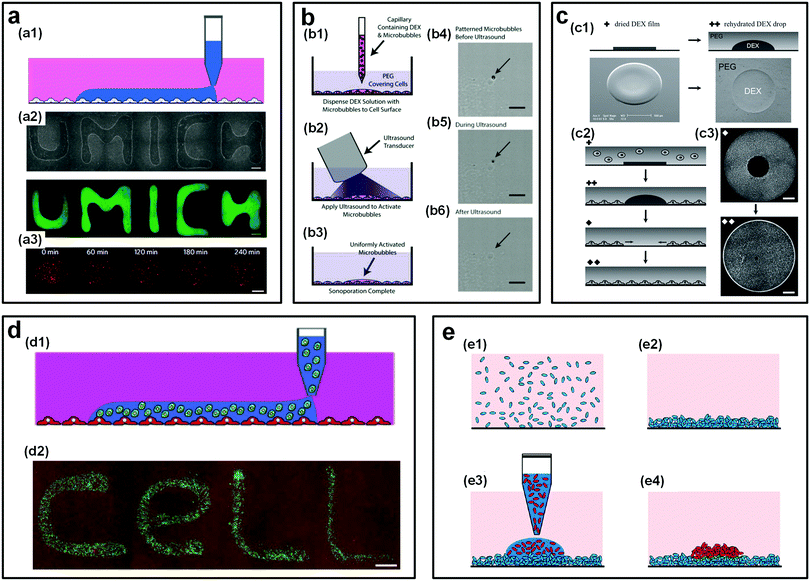 | ||
| Fig. 17 ATPS as a platform for micropatterning cells. (a) User-defined patterns of a reagent in aqueous droplets (DEX-rich) on a monolayer of cells in another aqueous substrate (PEG-rich). Scale bars in (a2) and (a3) are 1 mm and 500 μm, respectively. Reproduced with permission.182 Copyright 2009, Macmillan Publishers Limited. (b) Sonoporation by patterning microbubbles on monolayer cells: (b1–b3) Schematic of the experimental process. (b4–b6) Microscope images showing the experimental procedures. Scale bars are 5 μm. Reproduced with permission.183 Copyright 2013, Wiley-VCH. (c) Cell-exclusion zones formed by the rehydration of a dried DEX spot: (c1) Dried DEX spots rehydrating into droplets after adding the PEG-rich aqueous phase. (c2) Schematic showing the droplet rehydration and migration of cells into the excluded area. (c3) Experimental snapshots showing the cell exclusion and migration. Scale bars are 1 mm. Reproduced with permission.184 Copyright 2011, Wiley-VCH. (d) Non-contact cell printing on cells: (d1) Schematic showing user-defined cell printing on a monolayer of cells. (d2) An experimental image showing the user-defined pattern by cell printing on cells. The scale bar is 1 mm. Reproduced with permission.185 Copyright 2010, Wiley-VCH. (e) Schematic showing the layer-patterning process of one bacterial biofilm on another biofilm. Reproduced with permission.186 Copyright 2012, American Chemical Society. | ||
By patterning different types of cells, the ATPS-micropatterning technique can also be used to achieve cell cocultures and to study the interaction between various cell types. For instance, cocultures of HepG2 cells and NIH 3T3 fibroblast cells in ATPSs have been shown to produce much more albumins in comparison to those from monocultures of HepG2 cells. This result indicates an enhancement of the function of HepG2 cells when co-cultured with fibroblast cells.181 Furthermore, non-contact printing of cellular patterns in all-aqueous solutions by spatially patterning one cell type onto the surfaces of another cell-layer has also been demonstrated (Fig. 17d).185,187,188 Improved neuronal differentiation of mouse embryonic stem cells (mESC) is also observed when the mESCs are dispensed on the monolayer of PA6 stromal cells. In addition to exploring the interactions among different mammalian cells within ATPS cocultures, the same technique has also been utilized to study the interactions between different microbial cell types, such as patterning of a secondary confined bacterial biofilms onto the surface of primary larger biofilms to investigate the formation of biofilms (Fig. 17e).186 Moreover, by taking advantage of the low interfacial tension and the all-water nature of ATPSs, w/w emulsion droplets have been used to pattern and assemble particles and/or cells into spheroids and monolayers.189,190 The ability to assemble monolayered cell and cell–particle hybrid structures in liquid–liquid systems offers new opportunities to understand the interaction of cells or cells and particles as well as the formation of early tissue.
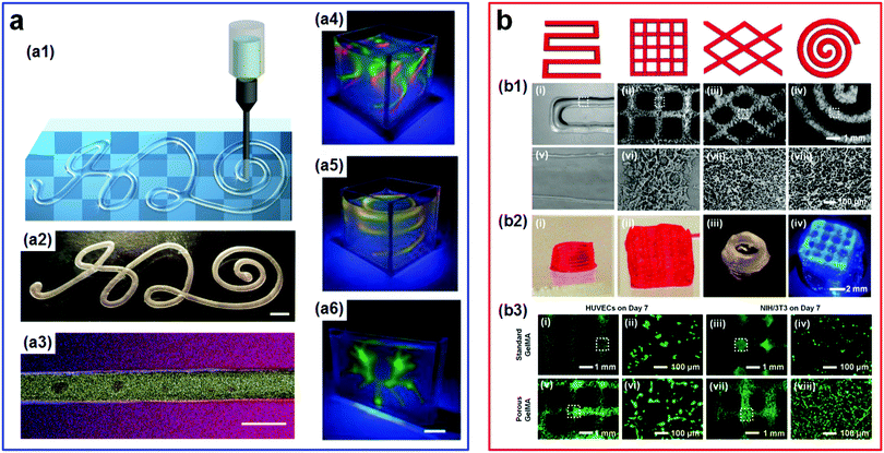 | ||
| Fig. 18 All-aqueous 3D bioprinting. (a1–a3) The 3D-printed stable all-aqueous tubules by the coacervation of oppositely charged PEs at w/w interfaces: (a1) Schematic of the designed “H2O” pattern. (a2) Image of the printed “H2O” pattern in water. The scale bar is 3 mm. (a3) The confocal microscope images showing the structured all-aqueous tubules where red, blue, and yellow colors indicate the rhodamine-labeled PEG, anthracene-labeled polyanion, and FITC-labeled dextran, respectively. The scale bar is 100 mm. Reproduced with permission.191 Copyright 2019, Elsevier. (a4–a6) Optical images illustrating freeform, reconfigurable all-aqueous architectures of PAA-DEX inks in an aqueous substrate of PEO solutions under UV light: (a4) The double-tornado-shaped structure, (a5) the double-spring-shaped structure, and (a6) the branched network. The scale bar is 1 cm. Reproduced with permission.192 Copyright 2019, WILEY-VCH. (b) The extrusion 3D bioprinting of the ATPS emulsion bioink with designed patterns. (b1) Optical images of corresponding bioprinted patterns: (i and v) Standard GelMA hydrogels; (ii–iv, vi–viii) porous GelMA hydrogels. (b2) Photographs of 3D-bioprinted multi-layered patterns: (i and ii) Standard GelMA hydrogels; (iii and iv) porous GelMA hydrogels. (b3) Fluorescence images of bioprinted HUVECs and NIH/3T3 fibroblasts in: (i–iv) Standard GelMA hydrogel patterns; (v–viii) porous GelMA hydrogel patterns, both of which are on Day 7 of culture. Reproduced with permission.193 Copyright 2018, WILEY-VCH. | ||
4.4 Microfluidic separation of cells and biomolecules
The traditional applications of ATPSs are limited to separating biological particles such as biomolecules, organelles, and whole cells in a macroscaled setup. The migration of this technology into microscale dimensions, such as through microfluidics, can significantly improve the separation efficiency. This high efficiency comes from the short diffusion distance of cells/biomolecules as well as the large surface area-to-volume ratio of the phase boundary inside the microchannels.196 The incorporation of ATPSs into the microfluidic device has enabled the efficient separation of cells, as summarized chronologically in Table 4.196–203 For instance, the separation of leukocytes (WBC) and erythrocytes (RBC) is much more efficient in ATPS-based microfluidic channels than that using the conventional batch approach. In a typical experiment, leukocytes and erythrocytes are first infused into a parallel microfluidic channel with flowing PEG and DEX aqueous solutions. Due to their different affinities, leukocytes and erythrocytes can be spontaneously enriched into the PEG and DEX phases, respectively (Fig. 19a). The enriched concentration of leukocytes is significantly increased by more than 7.13 fold relative to the control group that does not involve any ATPSs.197 This high effectiveness of cell separation is further demonstrated by comparing the recovery rate in microfluidic ATPS and conventional ATPS batch techniques. Up to 99% of erythrocytes and 96% of leukocytes can be recovered via the microfluidic ATPS technique, much larger than those [erythrocytes (97%) and leukocytes (15%)] via the conventional ATPS batch approach.201| Year | Types of cells and biomolecules | ATPSs (average Mw if available) | Ref. |
|---|---|---|---|
| (a) Cells | |||
| 2004 | Plant cell aggregates (strawberry) | PEG (6 kDa) + DEX (486 kDa) | 200 |
| 2005 | Chinese Hamster Ovary (CHO-K1) cells | PEG (8 kDa) + DEX (500 kDa) | 199 |
| 2009 | Whole blood cells (erythrocytes & leukocytes) | PEG (8 kDa) + DEX (500 kDa) | 197 |
| 2009 | Whole blood cells (erythrocytes & leukocytes), Jurkat cells | PEG (3.35 kDa, 6 kDa, 8 kDa) + DEX (40 kDa, 500 kDa) | 201 |
| 2010 | Jurkat cells | PEG (6 kDa) + DEX (500 kDa) | 203 |
| (b) Biomolecules | |||
| 2007 | Bovine serum albumin (BSA) | PEG (8 kDa) + DEX (500 kDa) | 204 |
| 2008 | Glutathione S-transferase (GST) & protein AcGFP1 | PEG (4 kDa) + KH2PO4/K2HPO4 | 205 |
| 2008 | BSA and ovalbumin | PEG (6 kDa), P-PEG (6 kDa) + DEX (500 kDa) | 206 |
| 2010 | Bacteriorhodopsin (BR) | PEG (8 kDa) + KH2PO4/K2HPO4 | 207 |
| 2011 | DNA, proteins (BSA, beta-galactosidase, carbonic anhydrase) | PEG (6 kDa, 8 kDa, 35 kDa), P-PEG (6 kDa) + DEX (Mw = 10 kDa, 500 kDa) | 208 |
| 2012 | Immunoglobulin (IgG) | PEG (3.35 kDa) + NaH2PO4/K2HPO4 | 209 |
| 2014 | BSA | PEG (4 kDa) + (NH4)2SO4 | 210 |
| 2014 | Amino acids (glutamic acid, lysine, tryptophan) | PEG (6 kDa) + sodium caseinate | 211 |
| 2014 | Mycotoxin ochratoxin A (OTA) | PEG (8 kDa, 20 kDa) + NaH2PO4/K2HPO4 | 212 |
| 2015 | α-Amylase | PEG (6 kDa) + K2HPO4 | 213 |
| 2018 | Ammonium carbonate | PEG (8 kDa) + DEX (500 kDa) | 214 |
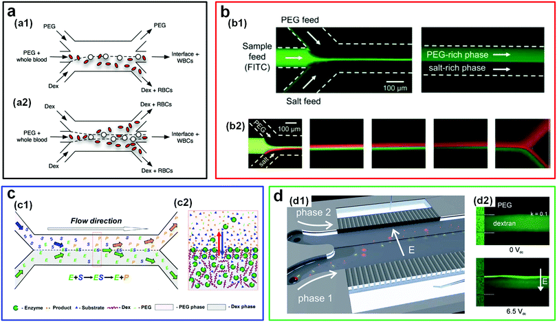 | ||
| Fig. 19 ATPS-based microfluidics as a platform for separating cells and biomolecules. (a) Schematic illustrating the separation of blood cells between PEG and DEX parallel flows in microfluidic channels: (a1) The configuration with two immiscible streams (PEG/DEX). (a2) The configuration with three immiscible streams (DEX/PEG/DEX). Reproduced with permission.197 Copyright 2008, Springer Science + Business Media. (b) Fluorescence microscope images showing the partitioning of samples by PEG/salt parallel flows in a microchannel including: (b1) Partitioning of FITC-containing samples, and (b2) binary partitioning of bovine serum albumin (BSA, green) and b-galactosidase (red) at different downstream locations. Reproduced with permission.205 Copyright 2008, Royal Society of Chemistry. (c) Schematics illustrating the enzymatic reaction and separation of the reaction product with an ATPS (DEX/PEG): (c1) In a double Y-branched microchannel and (c2) at a w/w interface. Reproduced with permission.214 Copyright 2017, Elsevier. (d) Electroextraction of biomolecules in ATPSs: (d1) Schematic illustrating a microfluidic device for electro-extracting molecules across the w/w interface, where coloured spheres (red) and rods (yellow) denote different molecules. Reproduced with permission.198 Copyright 2012, Royal Society of Chemistry. (d2) Fluorescence microscope images illustrating the concentration field of BSA in PEG/DEX trilaminated flows without electric fields (top) and with an electric field (bottom). Reproduced with permission.208 Copyright 2011, IOP Publishing. | ||
The continuous microfluidic ATPSs have also improved the efficiency in collection and enrichment of biomolecules, as summarized chronologically in Table 4.204–215 For instance, trace amounts of small molecules like fluorescein isothiocyanate (FITC) that initially dissolve in the salt-rich phase can be efficiently recovered into the PEG-rich phase in a parallel flow of salt- and PEG-rich streams. At the downstream, the FITC samples are almost completely enriched into the PEG-rich phase (Fig. 19b1).205 The separation of different proteins, bovine serum albumin (BSA) and b-galactosidase, can also be achieved by utilizing a PEG/salt ATPS, where BSA and b-galactosidase can be almost entirely separated (Fig. 19b2).205 In another work, by combining the use of ATPSs and a double Y-branched microfluidic device, biocatalysis and separation processes are realized in a single step, in which the enzymes mainly stay in the DEX phase and the resulting products mainly partition into the PEG phase (Fig. 19c). Consequently, the enzymatic reaction rate is greatly improved and can be as high as 500 times compared to that of the conventional ATPS approach.214
To enhance the sample transfer between the coflowing streams made of an ATPS, electric force can be introduced into the microfluidic device.198,204,208,216–218 The electrophoretic transport of the charged samples is typically faster than the transport via diffusion, known as “electroextraction”.219 The microfluidic design for separating proteins and DNAs is schematically illustrated in Fig. 19d1, in which electrodes are integrated into two sides of the comb-like channel walls and an electric field can be imposed perpendicularly onto the w/w interface.198 A typical result shows that proteins (fluorescently labelled BSA) with a strong affinity (partitioning coefficient k = 0.1) in the DEX phase can be enriched in a narrow band near the upper aqueous–aqueous interface when an electric field is applied (Fig. 19d2).208 The incorporation of an electric field into the microfluidic ATPS technique suggests a new approach to control the spatial distribution of biomolecules in microfluidic channels. This control can be realized because of the combined effect of partitioning affinity and electrophoretic transport. Apart from separations of cells and biomolecules, the continuous microfluidic ATPS technique has also been applied to other applications, such as determining the partitioning coefficients of biomolecules,220 evaluating the phase diagram of ATPSs,221 investigating the phase separation of ATPSs,222 and enhancing the delivery of cells and biomolecules in microchannels.223 More sophisticated approaches to manipulate a large number of biologically active ingredients and to isolate and retrieve single target ingredients, such as single cells,224,225 on all-aqueous based microfluidic chips are also expected in future studies. All these applications highlight that ATPSs can provide simple and efficient strategies for a wide range of applications that involve transport of cells or biomolecules across the aqueous–aqueous interface.
5. Challenges and perspectives
Recent advances in ATPSs have enabled controllable generation and stabilization of all-aqueous jets and droplets, and demonstrated diverse applications ranging from manipulating particles, designing artificial cells, preparing biocompatible microparticles, engineering cell micropatterning and 3D bioprinting, to separating cells and biomolecules in microfluidic channels in all-water environments. Despite these exciting and compelling developments, there remain significant research gaps and opportunities (Fig. 20) to understand ATPSs and to leverage their unique characteristics in potential all-aqueous-based applications.5.1 A deeper understanding of the aqueous–aqueous interface
The first challenge is the lack of a deep understanding of the properties of w/w interfaces. Since the properties of w/w interfaces are distinctly different from those of o/w interfaces, systematic studies on the physics of the interface and of the interplay between phase separation in ATPSs and the dynamics of w/w interfaces are urgently needed. For instance, the theoretical prediction on the breakup of the low-tension aqueous–aqueous jet is not consistent with the experimental observation.23 This inconsistency indicates that there might be a new physical mechanism that accounts for the breakup of low-interfacial tension liquid jets.226 So far, theory and numerical simulation have helped estimate the thickness of the w/w interface to be tens of nanometers87 to a few hundred nanometers;88 however, these estimations have not yet been verified by experimental measurements. To this end, advanced techniques that are capable of measuring the physical thickness of the aqueous–aqueous interface are required. Moreover, the adsorption and desorption dynamics of various colloidal particles, such as spherical and nonspherical, isotropic and anisotropic particles, at the aqueous–aqueous interface,105 are critically important to produce and understand stable all-aqueous Pickering emulsion droplets. For example, the efficient stabilization of w/w emulsion droplets via 2D poly(lactide) (PLA) plates with tunable dimensions and differentiated coronal chemistry is not clearly understood. The roles of many physical and chemical parameters, such as the particle size and the electric charges/ions,227–229 in the interfacial thermodynamics and phase behavior in a diverse range of ATPSs,230–233 for instance, in the phase-separated ATPS of organic aerosol droplets in atmospheric chemistry,234–239 still need a systematic exploration. These understandings will further help inspire new strategies to produce all-aqueous emulsion droplets and to stabilize these emulsion droplets, thus leading to new opportunities to engineering ATPS-based interfacial structures.5.2 Design and discovery of new ATPSs
The ultralow interfacial tension (several μN m−1) and relatively high viscosity (hundreds of mPa·s) of most common ATPSs, especially the widely used PEG–DEX systems, largely hinder the fabrication of w/w emulsion droplets in microfluidic channels. The low ratio of interfacial tension to viscosity indicates a particularly slow breakup of aqueous jets into droplets. Although ATPSs composed of inorganic salts and polymers have a relatively high interfacial tension and a low viscosity,240 the high osmolality associated with the concentrated salt-rich aqueous phase is harmful to many cells and biomolecules. To address this issue, ATPSs composed of custom-designed biocompatible macromolecules241 that meet the required fluid properties for targeted applications are anticipated in future work.Liquid–liquid phase separation (LLPS) in all-aqueous droplets offers a novel route to mimic biological properties of the cells. The spontaneous phase separation during the formation of membraneless organelles is found to be related to cell apoptosis and aging-associated diseases.242,243 More generally, LLPS is shown to be associated with some neurodegenerative disorders,244 such as the fatal amyotrophic lateral sclerosis (ALS).245,246 Because of their simplicity, versatility and low cost, synthetic ATPSs are expected to play a big role as model systems for compartmentalizing cellular organelles and thus to facilitate understanding the biophysical mechanisms of LLPS-driven processes and systems.247 However, common ATPSs, which involve polymers and salts like PEG/DEX, PEG/gelatin, and PEG/salt as incompatible solutes, differ significantly from the real intracellular environment.17 Therefore, new compositions of ATPSs that can mimic the cytoplasmic environment are urgently needed.248–252 Some new incompatible macromolecules, such as proteins and RNAs, that are directly extracted from cells may be good candidates to mimic the real cytoplasmic environment.
5.3 Fabrication of biomimetic materials with novel and complex structures
With increasing advances in the understanding of ATPSs and w/w interfaces, more applications will emerge. For instance, the low interfacial tension of ATPSs enables the formation of stable w/w jets which have great potential in biomedical applications. Most of the current works in the literature focus on the formation of biomaterials from the templates of w/w emulsion droplets, such as fabrication of microparticles and microcapsules. However, the fabrication of highly structured biomaterials from the w/w jets is rarely achieved, which might inspire fabrication of new structures.253–256 For instance, externally perturbing w/w jets with very low interfacial tensions may give rise to wave-like patterns at the w/w interface,28 which are hard to realize in the traditional o/w interface.257,258 By incorporating polymerizations, some unique structures, such as fish fin-like biomaterials, can be fabricated. Another aspect involves construction of complex and stable all-liquid reconfigurable structures by utilizing the low interfacial tension and interfacial reactions like the complexation of oppositely charged species, such as polyelectrolytes or functionalized particles, at the w/w interface.259–261 The encapsulation of living and active matter might have great potential to produce a new class of motile biomaterials such as self-healing or smart structures.262–264 In particular, incorporating the emerging 3D-printing technology into ATPSs may facilitate constructing some all-aqueous-based highly hierarchical structures like emulsion-packed structures and tissue constructs.265–2686. Conclusions
In summary, we firstly present the interfacial dynamics of all-aqueous jets without/with external stimuli, and summarize the strategies to fabricate all-aqueous simple and complex droplets and their stabilization. A variety of biomedical applications that take advantage of the unique properties of aqueous–aqueous interfaces (ultralow interfacial tension, all-water nature, and phase separation behavior) are then reviewed; these include design of artificial cells and cyto-mimetic materials within w/w droplets, synthesis of biomaterials from w/w droplet templates, ATPS-based cell micropatterning and 3D bioprinting, as well as separation of cells and biomolecules in microfluidic channels. Finally, we discuss the current challenges and future opportunities in the area of ATPSs. Considerable progress has been made in this emerging field. However, more work still needs to be done to overcome the current challenges and to expand ATPS-based applications towards a much wider range of practical applications. The rapidly emerging understanding of ATPSs brings enormous potential for mimicking the LLPS processes that have important implications in the development of cells, age-related diseases, and neurodegenerative disorders, as well as opportunities for new technologies such as 3D printing of all-aqueous-based highly biocompatible organs with promise for translation into clinical applications.Conflicts of interest
There are no conflicts to declare.Acknowledgements
This research was supported by the General Research Fund (No. 17306315, 17329516, 17304017, 17304418, and 17307919), the Collaborative Research Fund (C6004-14G) from the Research Grants Council of Hong Kong, the Seed Funding Programme for Basic Research (No. 201811159241, and 201711159249) and the Seed Funding for Strategic Interdisciplinary Research Scheme from the University of Hong Kong, as well as the Sichuan Science and Technology Program (2018JZ0026).References
- R. Hatti-Kaul, Aqueous two-phase systems: methods and protocols, Springer, 2000, pp. 1–10 Search PubMed.
- H. Walter, Partitioning in aqueous two-phase system: theory, methods, uses, and applications to biotechnology, Elsevier, 2012 Search PubMed.
- P.-Å. Albertsson, Nature, 1958, 182, 709 CrossRef CAS.
- R. Hatti-Kaul, Aqueous two-phase systems: methods and protocols, Springer Science & Business Media, 2000 Search PubMed.
- A. L. Grilo, M. Raquel Aires-Barros and A. M. Azevedo, Sep. Purif. Rev., 2016, 45, 68–80 CrossRef.
- Y. K. Yau, C. W. Ooi, E.-P. Ng, J. C.-W. Lan, T. C. Ling and P. L. Show, Bioresour. Bioprocess., 2015, 2, 49 CrossRef.
- R. R. Soares, A. M. Azevedo, J. M. Van Alstine and M. R. Aires-Barros, Biotechnol. J., 2015, 10, 1158–1169 CrossRef CAS.
- A. G. Teixeira, R. Agarwal, K. R. Ko, J. Grant-Burt, B. M. Leung and J. P. Frampton, Adv. Healthcare Mater., 2018, 7, e1701036 CrossRef.
- S. Raja, V. R. Murty, V. Thivaharan, V. Rajasekar and V. Ramesh, Sci. Technol., 2011, 1, 7–16 Search PubMed.
- F. Mashayekhi, A. S. Meyer, S. A. Shiigi, V. Nguyen and D. T. Kamei, Biotechnol. Bioeng., 2009, 102, 1613–1623 CrossRef CAS.
- G. Ao, J. K. Streit, J. A. Fagan and M. Zheng, J. Am. Chem. Soc., 2016, 138, 16677–16685 CrossRef CAS PubMed.
- G. Ao, C. Y. Khripin and M. Zheng, J. Am. Chem. Soc., 2014, 136, 10383–10392 CrossRef CAS PubMed.
- A. Hamta and M. R. Dehghani, J. Mol. Liq., 2017, 231, 20–24 CrossRef CAS.
- G. D. Rodrigues, M. D. C. H. da Silva, L. H. M. da Silva, F. J. Paggioli, L. A. Minim and J. S. dos Reis Coimbra, Sep. Purif. Technol., 2008, 62, 687–693 CrossRef CAS.
- Å. Gustafsson, H. Wennerström and F. Tjerneld, Polymer, 1986, 27, 1768–1770 CrossRef.
- P.-Å. Albertsson, Adv. Protein Chem., Elsevier, 1970, vol. 24, pp. 309–341 Search PubMed.
- Y. Song, A. Sauret and H. C. Shum, Biomicrofluidics, 2013, 7, 061301 CrossRef.
- C. D. Keating, Acc. Chem. Res., 2012, 45, 2114–2124 CrossRef CAS.
- S. Tomotika, Proc. R. Soc. A, 1935, 150, 322–337 CrossRef.
- P. Guillot, A. Colin, A. S. Utada and A. Ajdari, Phys. Rev. Lett., 2007, 99, 104502 CrossRef PubMed.
- A. Fragkopoulos, P. Ellis and A. Fernandez-Nieves, Eur. Phys. J., 2015, 36, 055023 CrossRef.
- H. Cheung Shum, J. Varnell and D. A. Weitz, Biomicrofluidics, 2012, 6, 012808 CrossRef PubMed.
- S. D. Geschiere, I. Ziemecka, V. van Steijn, G. J. Koper, J. H. Esch and M. T. Kreutzer, Biomicrofluidics, 2012, 6, 022007 CrossRef PubMed.
- L. Shang, Y. Cheng and Y. Zhao, Chem. Rev., 2017, 117, 7964–8040 CrossRef CAS PubMed.
- A. Perazzo, J. K. Nunes, S. Guido and H. A. Stone, Proc. Natl. Acad. Sci. U. S. A., 2017, 114, E8557–E8564 CrossRef CAS.
- Y. Yu, L. Shang, J. Guo, J. Wang and Y. Zhao, Nat. Protoc., 2018, 13, 2557–2579 CrossRef CAS.
- S. Y. Mak, Y. Chao and H. C. Shum, RSC Adv., 2017, 7, 3287–3292 RSC.
- S. Y. Mak, Z. Li, A. Frere, T. C. Chan and H. C. Shum, Sci. Rep., 2014, 4, 6675 CrossRef CAS PubMed.
- Z. Li, S. Y. Mak, A. Sauret and H. C. Shum, Lab Chip, 2014, 14, 744–749 RSC.
- V. Gnyawali, M. Saremi, M. C. Kolios and S. S. H. Tsai, Biomicrofluidics, 2017, 11, 034104 CrossRef PubMed.
- A. Sauret, C. Spandagos and H. C. Shum, Lab Chip, 2012, 12, 3380–3386 RSC.
- T. Kong, Z. Liu, L. Wang and H. C. Shum, Phys. Rev. Appl., 2015, 3, 034010 CrossRef.
- Y. Song, Z. Liu, T. Kong and H. C. Shum, Chem. Commun., 2013, 49, 1726–1728 RSC.
- T. Kong, H. A. Stone, L. Wang and H. C. Shum, Proc. Natl. Acad. Sci. U. S. A., 2018, 201801053 Search PubMed.
- S. G. Jones, N. Abbasi, B.-U. Moon and S. S. Tsai, Soft Matter, 2016, 12, 2668–2675 RSC.
- S. J. Lee, J. Y. Kang, W. Choi and R. Kwak, Small, 2017, 13, 1601725 CrossRef.
- M. Nakano, Adv. Drug Delivery Rev., 2000, 45, 1–4 CrossRef CAS.
- G. Muschiolik, Curr. Opin. Colloid Interface Sci., 2007, 12, 213–220 CrossRef CAS.
- J. S. Huang and R. Varadaraj, Curr. Opin. Colloid Interface Sci., 1996, 1, 535–539 CrossRef CAS.
- D. R. Link, S. L. Anna, D. A. Weitz and H. A. Stone, Phys. Rev. Lett., 2004, 92, 054503 CrossRef CAS.
- J. Eggers and E. Villermaux, Rep. Prog. Phys., 2008, 71, 036601 CrossRef.
- B. U. Moon, N. Abbasi, S. G. Jones, D. K. Hwang and S. S. Tsai, Anal. Chem., 2016, 88, 3982–3989 CrossRef CAS.
- P. Zhu and L. Wang, Lab Chip, 2017, 17, 34–75 RSC.
- M. Mastiani, S. Seo, B. Mosavati and M. Kim, ACS Omega, 2018, 3, 9296–9302 CrossRef CAS.
- A. Rotem, A. R. Abate, A. S. Utada, V. Van Steijn and D. A. Weitz, Lab Chip, 2012, 12, 4263–4268 RSC.
- Z. Toprakcioglu, A. Levin and T. P. Knowles, Biomacromolecules, 2017, 18, 3642–3651 CrossRef CAS.
- M. Jeyhani, V. Gnyawali, N. Abbasi, D. K. Hwang and S. S. H. Tsai, J. Colloid Interface Sci., 2019, 553, 382–389 CrossRef CAS.
- H. T. Liu, H. Wang, W. B. Wei, H. Liu, L. Jiang and J. H. Qin, Small, 2018, 1801095 CrossRef.
- I. Ziemecka, V. van Steijn, G. J. M. Koper, M. Rosso, A. M. Brizard, J. H. van Esch and M. T. Kreutzer, Lab Chip, 2011, 11, 620–624 RSC.
- D. Lai, J. P. Frampton, H. Sriram and S. Takayama, Lab Chip, 2011, 11, 3551–3554 RSC.
- A. Sauret and H. C. Shum, Appl. Phys. Lett., 2012, 100, 154106 CrossRef.
- B. U. Moon, S. G. Jones, D. K. Hwang and S. S. Tsai, Lab Chip, 2015, 15, 2437–2444 RSC.
- Y. S. Song, Y. H. Choi and D. H. Kim, J. Chromatogr. A, 2007, 1162, 180–186 CrossRef CAS.
- Y. Song, Y. K. Chan, Q. Ma, Z. Liu and H. C. Shum, ACS Appl. Mater. Interfaces, 2015, 7, 13925–13933 CrossRef CAS.
- Y. H. Choi and Y. S. Song, J. Chromatogr. A, 2010, 1217, 3723–3728 CrossRef CAS.
- C. Zhou, P. Zhu, Y. Tian, X. Tang, R. Shi and L. Wang, Lab Chip, 2017, 17, 3310–3317 RSC.
- S. Y. Mak, Y. Chao, S. Rahman and H. C. Shum, Langmuir, 2018, 34, 926–932 CrossRef CAS.
- T. Cubaud, Phys. Fluids, 2009, 21, 091103 CrossRef.
- X. Hu and T. Cubaud, Phys. Rev. Lett., 2018, 121, 044502 CrossRef.
- V. B. Dang and S.-J. Kim, Lab Chip, 2017, 17, 286–292 RSC.
- H. Breisig and M. Wessling, Biomicrofluidics, 2015, 9, 044122 CrossRef.
- K. Akamatsu, R. Kurita, D. Sato and S.-I. Nakao, Langmuir, 2019, 35, 9825–9830 CrossRef CAS PubMed.
- Y. Chao, S. Y. Mak, Q. Ma, J. Wu, Z. Ding, L. Xu and H. C. Shum, Langmuir, 2018, 34, 3030–3036 CrossRef CAS.
- S. Davis, L. Illum and I. Walker, Int. J. Pharm., 1987, 38, 133–137 CrossRef CAS.
- I. Ziemecka, V. van Steijn, G. J. M. Koper, M. T. Kreutzer and J. H. van Esch, Soft Matter, 2011, 7, 9878–9880 RSC.
- Y. Song and H. C. Shum, Langmuir, 2012, 28, 12054–12059 CrossRef CAS PubMed.
- Y. Chao, S. Y. Mak, S. Rahman, S. Zhu and H. C. Shum, Small, 2018, 14, 1802107 CrossRef.
- C. Cui, C. Zeng, C. Wang and L. Zhang, Langmuir, 2017, 33, 12670–12680 CrossRef CAS.
- S. Guo, T. Yao, X. Ji, C. Zeng, C. Wang and L. Zhang, Angew. Chem., Int. Ed., 2014, 53, 7504–7509 CrossRef CAS.
- J. B. Boreyko, P. Mruetusatorn, S. T. Retterer and C. P. Collier, Lab Chip, 2013, 13, 1295–1301 RSC.
- H. Yuan, Q. Ma, Y. Song, M. Y. Tang, Y. K. Chan and H. C. Shum, Macromol. Chem. Phys., 2016, 218, 1600422 CrossRef.
- B. U. Moon, D. K. Hwang and S. S. Tsai, Lab Chip, 2016, 16, 2601–2608 RSC.
- M. Navi, N. Abbasi, M. Jeyhani, V. Gnyawali and S. Tsai, Lab Chip, 2018, 18, 3361–3370 RSC.
- M. Mastiani, S. Seo, S. M. Jimenez, N. Petrozzi and M. M. Kim, Colloids Surf., A, 2017, 531, 111–120 CrossRef CAS.
- C. Liu, W. Zheng, R. Xie, Y. Liu, Z. Liang, G. Luo, M. Ding and Q. Liang, Chin. Chem. Lett., 2019, 30, 457–460 CrossRef CAS.
- D. Choi, E. Lee, S. J. Kim and M. Han, Soft Matter, 2019, 15, 4647–4655 RSC.
- Q. Zhang, J. Chen and H. Gai, J. Mater. Sci., 2019, 54, 14905–14913 CrossRef CAS.
- J. Li, N. Mittal, S. Y. Mak, Y. Song and H. C. Shum, J. Micromech. Microeng., 2015, 25, 084009 CrossRef.
- K. Zhu, Y. Yu, Y. Cheng, C. Tian, G. Zhao and Y. Zhao, ACS Appl. Mater. Interfaces, 2019, 11, 4826–4832 CrossRef CAS.
- J. A. De Lora, F. A. Fencl, A. D. Y. Macias Gonzalez, A. Bandegi, R. Foudazi, G. P. Lopez, A. P. Shreve and N. J. Carroll, ACS Appl. Bio Mater., 2019, 2, 4097–4105 CrossRef CAS.
- L. Vobecká, E. Khafizova, T. Stragier, Z. Slouka and M. Přibyl, Microfluid. Nanofluid., 2017, 21, 51 CrossRef.
- P. Azizian, M. Azarmanesh, M. Dejam, M. Mohammadi, M. Shamsi, A. Sanati-Nezhad and A. A. Mohamad, Chem. Eng. Sci., 2019, 195, 201–207 CrossRef CAS.
- L. Ge, H. Jin, X. Li, D. Wei and R. Guo, Langmuir, 2019, 35, 3490–3497 CrossRef CAS.
- J.-P. Douliez, A. Perro, J.-P. Chapel, B. Goudeau and L. Béven, Small, 2018, 14, 1803042 CrossRef.
- K. Nishinari and E. Doi, Food hydrocolloids: structures, properties, and functions, Springer Science & Business Media, 2012 Search PubMed.
- M. J. Rosen and J. T. Kunjappu, Surfactants and interfacial phenomena, Wiley Online Library, 2004 Search PubMed.
- M. Vis, J. Opdam, I. S. J. van’t Oor, G. Soligno, R. van Roij, R. H. Tromp and B. H. Erné, ACS Macro Lett., 2015, 4, 965–968 CrossRef CAS.
- E. Scholten, L. M. Sagis and E. van der Linden, J. Phys. Chem. B, 2004, 108, 12164–12169 CrossRef CAS.
- B. P. Binks, Curr. Opin. Colloid Interface Sci., 2002, 7, 21–41 CrossRef CAS.
- X. Yao, Z. Liu, M. Ma, Y. Chao, Y. Gao and T. Kong, Small, 2018, 14, 1802902 CrossRef.
- B. P. Binks and T. S. Horozov, Colloidal particles at liquid interfaces, Cambridge University Press, 2006 Search PubMed.
- R. Tromp and E. Blokhuis, Macromolecules, 2013, 46, 3639–3647 CrossRef CAS.
- B. V. Schmidt, Macromol. Chem. Phys., 2018, 219, 1700494 CrossRef.
- E. Dickinson, Trends Food Sci. Technol., 2019, 83, 31–40 CrossRef CAS.
- S. D. Hann, K. J. Stebe and D. Lee, Langmuir, 2017, 33, 10107–10117 CrossRef CAS.
- L. Tea, T. Nicolai and F. Renou, Langmuir, 2019, 35, 9029–9036 CrossRef CAS.
- D. M. A. Buzza, P. D. I. Fletcher, T. K. Georgiou and N. Ghasdian, Langmuir, 2013, 29, 14804–14814 CrossRef CAS.
- A. T. Poortinga, Langmuir, 2008, 24, 1644–1647 CrossRef CAS.
- H. Firoozmand, B. S. Murray and E. Dickinson, Langmuir, 2009, 25, 1300–1305 CrossRef CAS.
- G. Balakrishnan, T. Nicolai, L. Benyahia and D. Durand, Langmuir, 2012, 28, 5921–5926 CrossRef CAS.
- D. C. Dewey, C. A. Strulson, D. N. Cacace, P. C. Bevilacqua and C. D. Keating, Nat. Commun., 2014, 5, 4670 CrossRef CAS PubMed.
- K. R. Peddireddy, T. Nicolai, L. Benyahia and I. Capron, ACS Macro Lett., 2016, 5, 283–286 CrossRef CAS.
- M. Inam, J. R. Jones, M. M. Pérez-Madrigal, M. C. Arno, A. P. Dove and R. K. O’Reilly, ACS Cent. Sci., 2018, 4, 63–70 CrossRef CAS.
- N. Chatsisvili, A. P. Philipse, B. Loppinet and R. H. Tromp, Food Hydrocolloids, 2017, 65, 17–23 CrossRef CAS.
- L. Keal, C. E. Colosqui, R. H. Tromp and C. Monteux, Phys. Rev. Lett., 2018, 120, 208003 CrossRef CAS.
- B. T. Nguyen, T. Nicolai and L. Benyahia, Langmuir, 2013, 29, 10658–10664 CrossRef CAS PubMed.
- R. A. de Freitas, T. Nicolai, C. Chassenieux and L. Benyahia, Langmuir, 2016, 32, 1227–1232 CrossRef CAS.
- B. S. Murray and N. Phisarnchananan, Food Hydrocolloids, 2016, 56, 161–169 CrossRef CAS.
- B. T. Nguyen, W. Wang, B. R. Saunders, L. Benyahia and T. Nicolai, Langmuir, 2015, 31, 3605–3611 CrossRef CAS.
- B. P. Binks and H. Shi, Langmuir, 2019, 35, 4046–4057 CrossRef CAS.
- J. Zhang, J. Hwang, M. Antonietti and B. Schmidt, Biomacromolecules, 2019, 20, 204–211 CrossRef CAS.
- J. P. Douliez, N. Martin, T. Beneyton, J. C. Eloi, J. P. Chapel, L. Navailles, J. C. Baret, S. Mann and L. Beven, Angew. Chem., Int. Ed., 2018, 57, 7780–7784 CrossRef CAS.
- Y. Song, U. Shimanovich, T. C. T. Michaels, Q. M. Ma, J. M. Li, T. P. J. Knowles and H. C. Shum, Nat. Commun., 2016, 7, 12934 CrossRef CAS.
- L.-H. Xue, C.-Y. Xie, S.-X. Meng, R.-X. Bai, X. Yang, Y. Wang, S. Wang, B. P. Binks, T. Guo and T. Meng, ACS Macro Lett., 2017, 6, 679–683 CrossRef CAS.
- Q. Ma, Y. Song, J. W. Kim, H. S. Choi and H. C. Shum, ACS Macro Lett., 2016, 5, 666–670 CrossRef CAS.
- T. Hanazawa and B. S. Murray, Langmuir, 2013, 29, 9841–9848 CrossRef CAS PubMed.
- B. S. Murray and N. Phisarnchananan, Food Hydrocolloids, 2014, 42, 92–99 CrossRef CAS.
- T. Hanazawa and B. S. Murray, Food Hydrocolloids, 2014, 34, 128–137 CrossRef CAS.
- H. Firoozmand and D. Rousseau, Food Hydrocolloids, 2014, 42, 204–214 CrossRef CAS.
- D. N. Cacace, A. T. Rowland, J. J. Stapleton, D. C. Dewey and C. D. Keating, Langmuir, 2015, 31, 11329–11338 CrossRef CAS.
- S. D. Hann, M. Goulian, D. Lee and K. J. Stebe, Soft Matter, 2015, 11, 1733–1738 RSC.
- A. Gonzalez-Jordan, T. Nicolai and L. Benyahia, Langmuir, 2016, 32, 7189–7197 CrossRef CAS.
- A. A. K. Das, B. W. Filby, D. A. Geddes, D. Legrande and V. N. Paunov, Mater. Horiz., 2017, 4, 1196–1200 RSC.
- W. J. Ganley, P. T. Ryan and J. S. van Duijneveldt, J. Colloid Interface Sci., 2017, 505, 139–147 CrossRef CAS.
- F. Pir Cakmak and C. D. Keating, Sci. Rep., 2017, 7, 3215 CrossRef.
- N. Abbasi, M. Navi and S. S. H. Tsai, Langmuir, 2018, 34, 213–218 CrossRef CAS.
- E. Ben Ayed, R. Cochereau, C. Dechance, I. Capron, T. Nicolai and L. Benyahia, Langmuir, 2018, 34, 6887–6893 CrossRef CAS.
- J.-F. Chen, J. Guo, T. Zhang, Z.-L. Wan, J. Yang and X.-Q. Yang, J. Agric. Food Chem., 2018, 66, 4200–4207 CrossRef CAS.
- S. N. Innes-Gold, C. J. Luby and C. R. Mace, Langmuir, 2018, 34, 7673–7680 CrossRef CAS.
- C. Griffith and H. Daigle, J. Colloid Interface Sci., 2018, 532, 83–91 CrossRef CAS.
- S. B. Celik, S. R. Dominici, B. W. Filby, A. A. Das, L. A. Madden and V. N. Paunov, Biomimetics, 2019, 4, 50 CrossRef.
- J. Zhang, B. Kumru and B. Schmidt, Langmuir, 2019, 35, 11141–11149 CrossRef CAS.
- F. Qu, T. Meng, Y. Dong, H. Sun, Q. Tang, T. Liu and Y. Wang, ACS Appl. Mater. Interfaces, 2019, 11, 35613–35621 CrossRef CAS.
- S. D. Hann, K. J. Stebe and D. Lee, ACS Appl. Mater. Interfaces, 2017, 9, 25023–25028 CrossRef CAS.
- L. Zhang, L. H. Cai, P. S. Lienemann, T. Rossow, I. Polenz, Q. Vallmajo-Martin, M. Ehrbar, H. Na, D. J. Mooney and D. A. Weitz, Angew. Chem., Int. Ed., 2016, 128, 13668–13672 CrossRef.
- J. R. Vieregg, M. Lueckheide, A. B. Marciel, L. Leon, A. J. Bologna, J. R. Rivera and M. V. Tirrell, J. Am. Chem. Soc., 2018, 140, 1632–1638 CrossRef CAS.
- H. Khemissi, H. Bassani, A. Aschi, I. Capron, L. Benyahia and T. Nicolai, Langmuir, 2018, 34, 11806–11813 CrossRef CAS.
- A. J. Dzieciol and S. Mann, Chem. Soc. Rev., 2012, 41, 79–85 RSC.
- E. Rideau, R. Dimova, P. Schwille, F. R. Wurm and K. Landfester, Chem. Soc. Rev., 2018, 47, 8572–8610 RSC.
- A. A. Hyman, C. A. Weber and F. Jülicher, Annu. Rev. Cell Dev. Biol., 2014, 30, 39–58 CrossRef CAS.
- H. Sakuta, T. Fujimoto, Y. Yamana, Y. Hoda, K. Tsumoto and K. Yoshikawa, Front. Chem., 2019, 7, 44 CrossRef CAS.
- C. D. Crowe and C. D. Keating, Interface Focus, 2018, 8, 20180032 CrossRef.
- M. S. Long, C. D. Jones, M. R. Helfrich, L. K. Mangeney-Slavin and C. D. Keating, Proc. Natl. Acad. Sci. U. S. A., 2005, 102, 5920–5925 CrossRef CAS PubMed.
- M. R. Helfrich, L. K. Mangeney-Slavin, M. S. Long, K. Y. Djoko and C. D. Keating, J. Am. Chem. Soc., 2002, 124, 13374–13375 CrossRef CAS.
- Y. Li, R. Lipowsky and R. Dimova, J. Am. Chem. Soc., 2008, 130, 12252–12253 CrossRef CAS.
- Y. Li, R. Lipowsky and R. Dimova, Proc. Natl. Acad. Sci. U. S. A., 2011, 108, 4731–4736 CrossRef CAS.
- C. P. Brangwynne, C. R. Eckmann, D. S. Courson, A. Rybarska, C. Hoege, J. Gharakhani, F. Jülicher and A. A. Hyman, Science, 2009, 324, 1729 CrossRef CAS.
- C. A. Strulson, R. C. Molden, C. D. Keating and P. C. Bevilacqua, Nat. Chem., 2012, 4, 941–946 CrossRef CAS.
- D. N. Cacace and C. D. Keating, J. Mater. Chem. B, 2013, 1, 1794–1803 RSC.
- Y. Song, T. C. Michaels, Q. Ma, Z. Liu, H. Yuan, S. Takayama, T. P. Knowles and H. C. Shum, Nat. Commun., 2018, 9, 2110 CrossRef PubMed.
- M. S. Long, A.-S. Cans and C. D. Keating, J. Am. Chem. Soc., 2008, 130, 756–762 CrossRef CAS.
- L. M. Dominak, E. L. Gundermann and C. D. Keating, Langmuir, 2009, 26, 5697–5705 CrossRef.
- Y. Li, H. Kusumaatmaja, R. Lipowsky and R. Dimova, J. Phys. Chem. B, 2012, 116, 1819–1823 CrossRef CAS.
- R. Lipowsky, J. Phys. Chem. B, 2018, 122, 3572–3586 CrossRef CAS.
- R. Dimova and R. Lipowsky, Adv. Mater. Interfaces, 2017, 4, 1600451 CrossRef.
- Y. Liu, R. Lipowsky and R. Dimova, Front. Chem., 2019, 7, 213 CrossRef CAS.
- H. Kusumaatmaja and R. Lipowsky, Soft Matter, 2011, 7, 6914–6919 RSC.
- D. Park, J. Cheng, J. Park, S. Shin, S.-H. Lee, B. H. Hong, S. H. Kim, J. Hyun and C. Yang, ACS Biomater. Sci. Eng., 2019 DOI:10.1021/acsbiomaterials.9b01216.
- R. J. Stenekes, O. Franssen, E. M. van Bommel, D. J. Crommelin and W. E. Hennink, Int. J. Pharm., 1999, 183, 29–32 CrossRef CAS.
- R. M. Hernández, G. Orive, A. Murua and J. L. Pedraz, Adv. Drug Delivery Rev., 2010, 62, 711–730 CrossRef PubMed.
- W. Jiang, M. Li, Z. Chen and K. W. Leong, Lab Chip, 2016, 16, 4482–4506 RSC.
- F. Yin Hsu, S.-C. Chueh and Y. Jiin Wang, Biomaterials, 1999, 20, 1931–1936 CrossRef.
- W. Li, L. Zhang, X. Ge, B. Xu, W. Zhang, L. Qu, C.-H. Choi, J. Xu, A. Zhang and H. Lee, Chem. Soc. Rev., 2018, 47, 5646–5683 RSC.
- U. Shimanovich, I. Efimov, T. O. Mason, P. Flagmeier, A. K. Buell, A. Gedanken, S. Linse, K. S. Åkerfeldt, C. M. Dobson and D. A. Weitz, ACS Nano, 2015, 9, 43–51 CrossRef CAS.
- X. Liu, Z. Toprakcioglu, A. J. Dear, A. Levin, F. S. Ruggeri, C. G. Taylor, M. Hu, J. R. Kumita, M. Andreasen and C. M. Dobson, Macromol. Rapid Commun., 2019, 40, 1800898 CrossRef.
- S. Ma, J. Thiele, X. Liu, Y. Bai, C. Abell and W. T. Huck, Small, 2012, 8, 2356–2360 CrossRef CAS.
- Q. Liu, M. Zhao, S. Mytnyk, B. Klemm, K. Zhang, Y. Wang, D. Yan, E. Mendes and J. H. van Esch, Angew. Chem., Int. Ed., 2019, 58, 547–551 CrossRef CAS PubMed.
- S. Mytnyk, I. Ziemecka, A. G. Olive, J. W. M. van der Meer, K. A. Totlani, S. Oldenhof, M. T. Kreutzer, V. van Steijn and J. H. van Esch, RSC Adv., 2017, 7, 11331–11337 RSC.
- N. Abbasi, M. Navi, J. K. Nunes and S. S. H. Tsai, Soft Matter, 2019, 15, 3301–3306 RSC.
- S. D. Hann, D. Lee and K. J. Stebe, Phys. Chem. Chem. Phys., 2017, 19, 23825–23831 RSC.
- Q. Ma, Y. Song, G. Baier, C. Holtze and H. C. Shum, J. Mater. Chem. B, 2016, 4, 1213–1218 RSC.
- T. Watanabe, I. Motohiro and T. Ono, Langmuir, 2019, 35, 2358–2367 CrossRef CAS.
- D. Velasco, E. Tumarkin and E. Kumacheva, Small, 2012, 8, 1633–1642 CrossRef CAS PubMed.
- Q. Ma, H. Yuan, Y. Song, Y. Chao, S. Y. Mak and H. C. Shum, Soft Matter, 2018, 14, 1552–1558 RSC.
- S. D. Hann, T. H. Niepa, K. J. Stebe and D. Lee, ACS Appl. Mater. Interfaces, 2016, 8, 25603–25611 CrossRef CAS PubMed.
- Y. Deng, Q. M. Ma, H. Yuan, G. C. Lum and H. C. Shum, J. Mater. Chem. B, 2019, 7, 3059–3065 RSC.
- Y. Y. Zou, J. Song, X. S. You, J. Y. Yao, S. T. Xie, M. L. Jin, X. Wang, Z. B. Yan, G. F. Zhou and L. L. Shui, ACS Appl. Mater. Interfaces, 2019, 11, 21227–21238 CrossRef CAS PubMed.
- N. Yeredla, T. Kojima, Y. Yang, S. Takayama and M. Kanapathipillai, Sci. Rep., 2016, 6, 27736 CrossRef CAS.
- M. González-González and M. Rito-Palomares, J. Chem. Technol. Biotechnol., 2019 DOI:10.1002/jctb.6173.
- E. Atefi, R. Joshi, J. A. Mann Jr and H. Tavana, ACS Appl. Mater. Interfaces, 2015, 7, 21305–21314 CrossRef CAS PubMed.
- J. P. Frampton, J. B. White, A. T. Abraham and S. Takayama, J. Visualized Exp., 2013, e50304 Search PubMed.
- H. Tavana, A. Jovic, B. Mosadegh, Q. Y. Lee, X. Liu, K. E. Luker, G. D. Luker, S. J. Weiss and S. Takayama, Nat. Mater., 2009, 8, 736–741 CrossRef CAS.
- J. P. Frampton, Z. Fan, A. Simon, D. Chen, C. X. Deng and S. Takayama, Adv. Funct. Mater., 2013, 23, 3420–3431 CrossRef CAS.
- H. Tavana, K. Kaylan, T. Bersano-Begey, K. E. Luker, G. D. Luker and S. Takayama, Adv. Funct. Mater., 2011, 21, 2920–2926 CrossRef CAS.
- H. Tavana, B. Mosadegh and S. Takayama, Adv. Mater., 2010, 22, 2628–2631 CrossRef CAS.
- T. Yaguchi, M. Dwidar, C. K. Byun, B. Leung, S. Lee, Y.-K. Cho, R. J. Mitchell and S. Takayama, Biomacromolecules, 2012, 13, 2655–2661 CrossRef CAS.
- H. Tavana and S. Takayama, Biomicrofluidics, 2011, 5, 013404 CrossRef.
- H. Tavana, B. Mosadegh, P. Zamankhan, J. B. Grotberg and S. Takayama, Biotechnol. Bioeng., 2011, 108, 2509–2516 CrossRef CAS PubMed.
- E. Atefi, S. Lemmo, D. Fyffe, G. D. Luker and H. Tavana, Adv. Funct. Mater., 2014, 24, 6509–6515 CrossRef CAS.
- Y. K. Chan, W. H. Yan, L. T. Hung, Y. Chao, J. Wu and H. C. Shum, ACS Appl. Mater. Interfaces, 2019, 11, 22869–22877 CrossRef CAS.
- G. Xie, J. Forth, Y. Chai, P. D. Ashby, B. A. Helms and T. P. Russell, Chem, 2019, 5, 2678–2690 CAS.
- G. Luo, Y. Yu, Y. Yuan, X. Chen, Z. Liu and T. Kong, Adv. Mater., 2019, 1904631 CrossRef.
- G.-L. Ying, N. Jiang, S. Maharjan, Y.-X. Yin, R.-R. Chai, X. Cao, J.-Z. Yang, A. K. Miri, S. Hassan and Y. S. Zhang, Adv. Mater., 2018, 30, 1805460 CrossRef.
- A. Hori, Y. Watabe, M. Yamada, Y. Yajima, R. Utoh and M. Seki, ACS Appl. Bio Mater., 2019, 2, 2237–2245 CrossRef CAS.
- Y. S. Zhang, K. Yue, J. Aleman, K. Mollazadeh-Moghaddam, S. M. Bakht, J. Yang, W. Jia, V. Dell’Erba, P. Assawes and S. R. Shin, Ann. Biomed. Eng., 2017, 45, 148–163 CrossRef.
- G. M. Walker, in Microtechnology for Cell Manipulation and Sorting, ed. W. Lee, P. Tseng and D. Di Carlo, Springer International Publishing, Cham, 2017, pp. 255–278 Search PubMed.
- J. R. SooHoo and G. M. Walker, Biomed. Microdevices, 2009, 11, 323–329 CrossRef.
- S. Hardt and T. Hahn, Lab Chip, 2012, 12, 434–442 RSC.
- K.-H. Nam, W.-J. Chang, H. Hong, S.-M. Lim, D.-I. Kim and Y.-M. Koo, Biomed. Microdevices, 2005, 7, 189–195 CrossRef PubMed.
- M. Yamada, V. Kasim, M. Nakashima, J. I. Edahiro and M. Seki, Biotechnol. Bioeng., 2004, 88, 489–494 CrossRef CAS PubMed.
- M. Tsukamoto, S. Taira, S. Yamamura, Y. Morita, N. Nagatani, Y. Takamura and E. Tamiya, Analyst, 2009, 134, 1994–1998 RSC.
- R. R. Soares, D. F. Silva, P. Fernandes, A. M. Azevedo, V. Chu, J. P. Conde and M. R. Aires-Barros, Biotechnol. J., 2016, 11, 1498–1512 CrossRef CAS.
- K. Vijayakumar, S. Gulati and J. B. Edel, Chem. Sci., 2010, 1, 447–452 RSC.
- G. Münchow, S. Hardt, J. P. Kutter and K. Drese, Lab Chip, 2007, 7, 98–102 RSC.
- R. J. Meagher, Y. K. Light and A. K. Singh, Lab Chip, 2008, 8, 527–532 RSC.
- G. Münchow, F. Schönfeld, S. Hardt and K. Graf, Langmuir, 2008, 24, 8547–8553 CrossRef.
- Y. S. Huh, C.-M. Jeong, H. N. Chang, S. Y. Lee, W. H. Hong and T. J. Park, Biomicrofluidics, 2010, 4, 014103 CrossRef.
- T. Hahn, G. Münchow and S. Hardt, J. Phys.: Condens. Matter, 2011, 23, 184107 CrossRef.
- D. Silva, A. Azevedo, P. Fernandes, V. Chu, J. Conde and M. Aires-Barros, J. Chromatogr. A, 2012, 1249, 1–7 CrossRef CAS PubMed.
- Y. Huang, T. Meng, T. Guo, W. Li, W. Yan, X. Li, S. Wang and Z. Tong, Microfluid. Nanofluid., 2014, 16, 483–491 CrossRef CAS.
- C. Campos, J. Park, P. Neužil, J. F. da Silva and A. Manz, RSC Adv., 2014, 4, 49485–49490 RSC.
- R. R. G. Soares, P. Novo, A. M. Azevedo, P. Fernandes, M. R. Aires-Barros, V. Chu and J. P. Conde, Lab Chip, 2014, 14, 4284–4294 RSC.
- U. Novak, M. Lakner, I. Plazl and P. Žnidaršič-Plazl, Microfluid. Nanofluid., 2015, 19, 75–83 CrossRef CAS.
- S.-X. Meng, L.-H. Xue, C.-Y. Xie, R.-X. Bai, X. Yang, Z.-P. Qiu, T. Guo, Y.-L. Wang and T. Meng, Chem. Eng. J., 2018, 335, 392–400 CrossRef CAS.
- R. Hu, X. Feng, P. Chen, M. Fu, H. Chen, L. Guo and B.-F. Liu, J. Chromatogr. A, 2011, 1218, 171–177 CrossRef CAS PubMed.
- G. Münchow, S. Hardt, J. P. Kutter and K. Drese, JALA, 2006, 11, 368–373 Search PubMed.
- T. Hahn and S. Hardt, Anal. Chem., 2011, 83, 5476–5479 CrossRef CAS PubMed.
- T. Hahn and S. Hardt, Soft Matter, 2011, 7, 6320–6326 RSC.
- M. L. Levine and M. Bier, Electrophoresis, 1990, 11, 605–611 CrossRef CAS.
- D. F. C. Silva, A. M. Azevedo, P. Fernandes, V. Chu, J. P. Conde and M. R. Aires-Barros, J. Chromatogr. A, 2017, 1487, 242–247 CrossRef CAS PubMed.
- D. Silva, A. Azevedo, P. Fernandes, V. Chu, J. Conde and M. Aires-Barros, J. Chromatogr. A, 2014, 1370, 115–120 CrossRef CAS PubMed.
- Y. Lu, Y. Xia and G. Luo, Microfluid. Nanofluid., 2011, 10, 1079–1086 CrossRef CAS.
- J. P. Frampton, D. Lai, H. Sriram and S. Takayama, Biomed. Microdevices, 2011, 13, 1043–1051 CrossRef CAS.
- L. Nan, M. Y. A. Lai, M. Y. H. Tang, Y. K. Chan, L. L. M. Poon and H. C. Shum, Small, 2019, 0, 1902889 CrossRef PubMed.
- F. Lan, B. Demaree, N. Ahmed and A. R. Abate, Nat. Biotechnol., 2017, 35, 640 CrossRef CAS PubMed.
- H. Y. Lo, Y. Liu, S. Y. Mak, Z. Xu, Y. Chao, K. J. Li, H. C. Shum and L. Xu, Phys. Rev. Lett., 2019, 123, 134501 CrossRef CAS PubMed.
- M. Vis, V. F. D. Peters, E. M. Blokhuis, H. N. W. Lekkerkerker, B. H. Erne and R. H. Tromp, Phys. Rev. Lett., 2015, 115, 078303 CrossRef PubMed.
- M. Vis, B. H. Erné and R. H. Tromp, Biointerphases, 2016, 11, 018904 CrossRef.
- A. Alizadeh and M. Wang, J. Colloid Interface Sci., 2019, 534, 195–204 CrossRef CAS.
- C. R. Mace, O. Akbulut, A. A. Kumar, N. D. Shapiro, R. Derda, M. R. Patton and G. M. Whitesides, J. Am. Chem. Soc., 2012, 134, 9094–9097 CrossRef CAS PubMed.
- M. G. Freire, A. F. M. Claudio, J. M. Araujo, J. A. Coutinho, I. M. Marrucho, J. N. C. Lopes and L. P. N. Rebelo, Chem. Soc. Rev., 2012, 41, 4966–4995 RSC.
- H. Passos, S. H. Costa, A. M. Fernandes, M. G. Freire, R. D. Rogers and J. A. P. Coutinho, Angew. Chem., Int. Ed., 2017, 56, 15058–15062 CrossRef CAS.
- B. A. Rogers, K. B. Rembert, M. F. Poyton, H. I. Okur, A. R. Kale, T. Yang, J. Zhang and P. S. Cremer, Proc. Natl. Acad. Sci. U. S. A., 2019, 116, 15784–15791 CrossRef CAS.
- A. Bertram, S. Martin, S. Hanna, M. Smith, A. Bodsworth, Q. Chen, M. Kuwata, A. Liu, Y. You and S. Zorn, Atmos. Chem. Phys., 2011, 11, 10995–11006 CrossRef CAS.
- M. Song, C. Marcolli, U. Krieger, A. Zuend and T. Peter, Atmos. Chem. Phys., 2012, 12, 2691–2712 CrossRef CAS.
- A. P. Ault, T. L. Guasco, O. S. Ryder, J. Baltrusaitis, L. A. Cuadra-Rodriguez, D. B. Collins, M. J. Ruppel, T. H. Bertram, K. A. Prather and V. H. Grassian, J. Am. Chem. Soc., 2013, 135, 14528–14531 CrossRef CAS PubMed.
- D. Stewart, C. Cai, J. Nayler, T. Preston, J. Reid, U. Krieger, C. Marcolli and Y. Zhang, J. Phys. Chem. A, 2015, 119, 4177–4190 CrossRef CAS.
- M. A. Freedman, Chem. Soc. Rev., 2017, 46, 7694–7705 RSC.
- K. Gorkowski, N. M. Donahue and R. C. Sullivan, Environ. Sci. Technol., 2017, 51, 12154–12163 CrossRef CAS PubMed.
- Y. T. Wu, Z. Q. Zhu and L. H. Mei, J. Chem. Eng. Data, 1996, 41, 1032–1035 CrossRef CAS.
- S. Mytnyk, A. G. L. Olive, F. Versluis, J. M. Poolman, E. Mendes, R. Eelkema and J. H. van Esch, Angew. Chem., Int. Ed., 2017, 56, 14923–14927 CrossRef CAS PubMed.
- Y. Shin and C. P. Brangwynne, Science, 2017, 357, eaaf4382 CrossRef PubMed.
- C. L. Klaips, G. G. Jayaraj and F. U. Hartl, J. Cell Biol., 2018, 217, 51 CrossRef CAS PubMed.
- A. Patel, H. O. Lee, L. Jawerth, S. Maharana, M. Jahnel, M. Y. Hein, S. Stoynov, J. Mahamid, S. Saha, T. M. Franzmann, A. Pozniakovski, I. Poser, N. Maghelli, L. A. Royer, M. Weigert, E. W. Myers, S. Grill, D. Drechsel, A. A. Hyman and S. Alberti, Cell, 2015, 162, 1066–1077 CrossRef CAS PubMed.
- B. N. Smith, S. D. Topp, C. Fallini, H. Shibata, H.-J. Chen, C. Troakes, A. King, N. Ticozzi, K. P. Kenna and A. Soragia-Gkazi, Sci. Transl. Med., 2017, 9, eaad9157 CrossRef PubMed.
- Y. C. Liao, M. S. Fernandopulle, G. Wang, H. Choi, L. Hao, C. M. Drerup, R. Patel, S. Qamar, J. Nixon-Abell, Y. Shen, W. Meadows, M. Vendruscolo, T. P. J. Knowles, M. Nelson, M. A. Czekalska, G. Musteikyte, M. A. Gachechiladze, C. A. Stephens, H. A. Pasolli, L. R. Forrest, P. St George-Hyslop, J. Lippincott-Schwartz and M. E. Ward, Cell, 2019, 179, 147–164 CrossRef CAS PubMed.
- S. Alberti, A. Gladfelter and T. Mittag, Cell, 2019, 176, 419–434 CrossRef CAS PubMed.
- X. Ge, A. J. Conley, J. E. Brandle, R. Truant and C. D. Filipe, J. Am. Chem. Soc., 2009, 131, 9094–9099 CrossRef CAS PubMed.
- W. M. Aumiller Jr, F. Pir Cakmak, B. W. Davis and C. D. Keating, Langmuir, 2016, 32, 10042–10053 CrossRef.
- C. P. Brangwynne, P. Tompa and R. V. Pappu, Nat. Phys., 2015, 11, 899–904 Search PubMed.
- L.-P. Bergeron-Sandoval, N. Safaee and S. W. Michnick, Cell, 2016, 165, 1067–1079 CrossRef CAS.
- S. F. Banani, H. O. Lee, A. A. Hyman and M. K. Rosen, Nat. Rev. Mol. Cell Biol., 2017, 18, 285 CrossRef CAS PubMed.
- C. Huang, J. Forth, W. Wang, K. Hong, G. S. Smith, B. A. Helms and T. P. Russell, Nat. Nanotechnol., 2017, 12, 1060 CrossRef CAS PubMed.
- M. F. Haase, K. J. Stebe and D. Lee, Adv. Mater., 2015, 27, 7065–7071 CrossRef CAS PubMed.
- L. Shang, Y. Yu, Y. Liu, Z. Chen, T. Kong and Y. Zhao, ACS Nano, 2019, 13, 2749–2772 CrossRef CAS PubMed.
- S. Wei, G. Qu, G. Luo, Y. Huang, H. Zhang, X. Zhou, L. Wang, Z. Liu and T. Kong, ACS Appl. Mater. Interfaces, 2018, 10, 11204–11212 CrossRef CAS PubMed.
- J. K. Nunes, C. Y. Wu, H. Amini, K. Owsley, D. Di Carlo and H. A. Stone, Adv. Mater., 2014, 26, 3712–3717 CrossRef CAS PubMed.
- H. Onoe, T. Okitsu, A. Itou, M. Kato-Negishi, R. Gojo, D. Kiriya, K. Sato, S. Miura, S. Iwanaga, K. Kuribayashi-Shigetomi, Y. T. Matsunaga, Y. Shimoyama and S. Takeuchi, Nat. Mater., 2013, 12, 584 CrossRef CAS PubMed.
- C. H. Evers, J. A. Luiken, P. G. Bolhuis and W. K. Kegel, Nature, 2016, 534, 364 CrossRef PubMed.
- Z. Yang, J. Wei, Y. I. Sobolev and B. A. Grzybowski, Nature, 2018, 553, 313–318 CrossRef CAS PubMed.
- Y. Wang, Y. Wang, D. R. Breed, V. N. Manoharan, L. Feng, A. D. Hollingsworth, M. Weck and D. J. Pine, Nature, 2012, 491, 51 CrossRef CAS PubMed.
- Y. Kim, H. Yuk, R. Zhao, S. A. Chester and X. Zhao, Nature, 2018, 558, 274 CrossRef CAS PubMed.
- G. Qu, Y. Li, Y. Yu, Y. Huang, W. Zhang, H. Zhang, Z. Liu and T. Kong, Angew. Chem., Int. Ed., 2019, 58, 10951–10955 CrossRef CAS PubMed.
- X. Liu, N. Kent, A. Ceballos, R. Streubel, Y. Jiang, Y. Chai, P. Y. Kim, J. Forth, F. Hellman and S. Shi, Science, 2019, 365, 264–267 CrossRef CAS PubMed.
- H. K. Lau, A. Paul, I. Sidhu, L. Li, C. R. Sabanayagam, S. H. Parekh and K. L. Kiick, Adv. Sci., 2018, 1701010 CrossRef PubMed.
- J. Forth, X. Liu, J. Hasnain, A. Toor, K. Miszta, S. Shi, P. L. Geissler, T. Emrick, B. A. Helms and T. P. Russell, Adv. Mater., 2018, 30, 1707603 CrossRef PubMed.
- J. Forth, P. Y. Kim, G. H. Xie, X. B. Liu, B. A. Helms and T. P. Russell, Adv. Mater., 2019, 31, 1806370 CrossRef PubMed.
- B. Grigoryan, S. J. Paulsen, D. C. Corbett, D. W. Sazer, C. L. Fortin, A. J. Zaita, P. T. Greenfield, N. J. Calafat, J. P. Gounley and A. H. Ta, Science, 2019, 364, 458–464 CrossRef CAS PubMed.
| This journal is © The Royal Society of Chemistry 2020 |

