
 Open Access Article
 This Open Access Article is licensed under a Creative Commons Attribution-Non Commercial 3.0 Unported Licence
Na2CO3-modified CaO-based CO2 sorbents: the effects of structure and morphology on CO2 uptake†
Alexey
Kurlov
 a,
Agnieszka M.
Kierzkowska
a,
Thomas
Huthwelker
b,
Paula M.
Abdala
*a and
Christoph R.
Müller
*a
a,
Agnieszka M.
Kierzkowska
a,
Thomas
Huthwelker
b,
Paula M.
Abdala
*a and
Christoph R.
Müller
*a
aETH Zürich, Laboratory of Energy Science and Engineering, Leonhardstrasse 21, CH 8092 Zürich, Switzerland. E-mail: abdalap@ethz.ch; muelchri@ethz.ch
bPSI, SLS, 5232 Villigen, Switzerland
First published on 15th October 2020
Abstract
Calcium looping (CaL) is a CO2 capture technique based on the reversible carbonation/calcination of CaO that is considered promising to reduce anthropogenic CO2 emissions. However, the rapid decay of the CO2 uptake of CaO over repeated cycles of carbonation and calcination due to sintering limits its implementation at the industrial scale. Thus, the development of material design strategies to stabilize the CO2 uptake capacity of CaO is paramount. The addition of alkali metal salts to CaO has been proposed as a strategy to mitigate the rapid loss of its cyclic CO2 uptake capacity. However, there are conflicting results concerning the effect of the addition of alkali metal carbonates on the structure and CO2 capacity of CaO. In this work, we aim at understanding the effect of the addition of Na2CO3 to CaO on the sorbent's structure and its CO2 uptake capacity. We demonstrate that under industrially-relevant conditions the addition of as little as 1 wt% of Na2CO3 reduces severely the CO2 uptake of CaO. Combining TGA, XAS and FIB-SEM analysis allowed us to attribute the performance degradation to the formation of the double salt Na2Ca(CO3)2 that induces strong sintering leading to a significant loss in the sorbent's pore volume. In addition, during the carbonation step the formation of a dense layer of Na2Ca(CO3)2 that covers unreacted CaO prevents its full carbonation to CaCO3.
Introduction
The continuous global economic growth results in a constant increase in the energy demand. Currently, over 80% of the total primary energy supply is derived from fossil fuels, i.e. coal, oil and natural gas.1 The combustion of fossil fuels releases large volumes of CO2 into the atmosphere which in turn is most likely linked to global warming.2 Besides energy saving strategies and the transition to renewable energy carriers, CO2 capture and storage (CCS) is expected to provide an appreciable contribution to the global reduction targets in CO2 emissions. Currently, the only industrially available CO2 capture technology is amine scrubbing.3 However, amine scrubbing is expensive and associated with the formation of hazardous by-products such as nitrosamines.4,5 Therefore, alternative CCS technologies are currently explored, with calcium looping (CaL) being one of the most promising candidates. CaL is based on the reversible carbonation–calcination reaction pair| CaO (s) + CO2 (g) ↔ CaCO3 (s), ΔH0298K = ±178 kJ mol−1 |
Recent work has explored the effect of the addition of the double salt (Li-K)2CO3 to CaO on its CO2 uptake.21 After 23 carbonation/calcination cycles a three times higher CO2 uptake was observed when compared to pure CaO.21 It was speculated that the addition of (Li-K)2CO3 prevents the formation of a CaCO3 layer that would otherwise impose a high diffusion resistance for CO2, thus providing a direct access for CO2 to unreacted CaO. However, a limitation of the studies described above is that the cyclic CO2 uptake of alkali metal salt-promoted CaO was determined under mild reaction conditions that are of little relevance for practical use, i.e. the calcination step was performed in pure N2 at T ≤ 850 °C. Furthermore, there has been very little insight into the morphological and structural modifications that arise from the addition of alkali metal salt promoters. Hence, in this work we study in detail the effect of the addition of the alkali salt Na2CO3 on the CO2 uptake of CaO under industrially relevant conditions. The CO2 uptake performance of sorbents is complemented by a detailed characterization of the alkali metal salt-induced structural and morphological changes of the sorbent using a combination of electron microscopy and X-ray absorption spectroscopy (XAS). These experiments allowed us to link the sorbents’ decreasing CO2 uptake to sintering that is induced by the formation of the low melting point double carbonate Na2Ca(CO3)2. Furthermore, Na2Ca(CO3)2 was found to be stable under both carbonation and calcination conditions and to cover the surface of unreacted CaO preventing in turn the carbonation reaction to proceed rapidly.
Experimental
Material preparation
Commercial CaCO3 (Fischer Chemicals, CAS: 471-34-1, analytical reagent grade) and Na2CO3 (Acros Organics, CAS: 497-19-8, 99.5% purity) were used for the synthesis of the CO2 sorbents (Fig. S1, ESI†). To achieve a homogeneous distribution of the sodium salt modifier, a wet ball-milling technique following a reported method was employed.14 Specifically, 7 g of the precursor powders, mixed with 10 mL of deionized water, were ball-milled in a 45 mL Si3N4 jar containing 5 mm Si3N4 balls. The ball-milling time was 48 h at 500 rpm. After ball milling, the suspension obtained was dried in an oven overnight at 100 °C. The following nomenclature is used for the samples: Ca/xNa, whereby x refers to the quantity of Na2CO3 (wt%). The following values for x were used: 1, 3, 6, 10 and 20 wt%. Pure ball-milled CaCO3 was used as the reference material for the CO2 uptake experiments (referred to as Ca/0Na).The reference Na2Ca(CO3)2 material was synthesized from a stoichiometric mixture of Na2CO3 and CaCO3 at 800 °C in a CO2 atmosphere for 2 h.
Materials characterization
The mass ratio of Na![[thin space (1/6-em)]](https://www.rsc.org/images/entities/char_2009.gif) :Ca in the sorbents was determined by inductively coupled plasma optical emission spectroscopy (ICP-OES) using an Agilent 5100 VDV instrument; the samples were digested in aqua regia.
:Ca in the sorbents was determined by inductively coupled plasma optical emission spectroscopy (ICP-OES) using an Agilent 5100 VDV instrument; the samples were digested in aqua regia.
The crystallinity and phase composition of the sorbents were analyzed by X-ray powder diffraction (XRD). The XRD data were collected using a PANalytical Empyrean X-ray diffractometer equipped with a Bragg–Brentano HD mirror, which was operated at 45 kV and 40 mA using CuKα radiation (λ = 1.54 Å). The materials were examined within the 2θ range of 5–90° using a step size of 0.0167°. The scan time per step was 1 s.
N2 physisorption (Quantachrome NOVA 4000e) was used to determine the surface area and pore volume of the CO2 sorbents in both the as-prepared and calcined states. Prior to the measurements, all samples were degassed at 300 °C for at least 2 h. The Brunauer–Emmett–Teller (BET)24 and the Barrett–Joyner–Halenda (BJH)25 models were used to calculate the surface area and pore volume, respectively.
The particle size and morphology of the CO2 sorbents synthesized was examined using scanning electron microscopy (SEM). SEM was performed on a LEO Gemini 1530 (Zeiss, Germany) at 5 kV acceleration voltage. Prior to imaging, all samples were sputtered with a thin (ca. 3 nm) layer of Pt. Energy-dispersive X-ray spectroscopy (EDX) mapping was obtained at 20 kV acceleration voltage on samples without a Pt coating. Cross-sections of the synthesized materials were prepared by focused ion beam (FIB) equipped with a Ga ion source and imaged with a high-resolution FE-SEM (Zeiss, FIB-SEM NVision 40). For elemental mapping, an Edax EDX detector was used.
X-ray absorption spectroscopy (XAS) experiments were performed at the Phoenix Beamlines (X07MA/B) at the Swiss Light Source (SLS, PSI, Villigen, Switzerland). Data were collected in fluorescence mode (Vortex four-element Si-drift diode detector). For the reference materials, total electron yield signals were also acquired and compared to the fluorescence-detected data to account for self-absorption. The incident intensity I0 was measured as the total electron yield signal using a 0.5 μm thin polyester foil coated with Ni. All XAS measurements were performed in a vacuum chamber (ca. 2.5 × 10⁻⁵ mbar) using materials supported on a copper plate, while metallic indium was used for sample fixation. The data were acquired in the range of 950–1600 eV and 3900–4800 eV for the Na and Ca K-edges, respectively. XAS data processing was performed using the Athena software (Demeter 0.9.25 software package).26 Energy calibration was performed using NaCl (1075.6 eV at the inflexion point).27
CO2 capture test
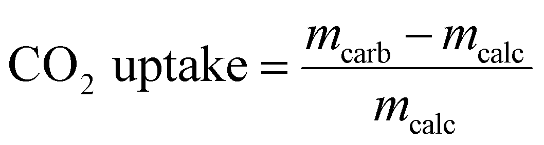
The materials synthesized were first assessed with regards to their CO2 uptake performance in a TGA (Mettler Toledo TGA/DSC 3). In a typical TGA experiment 10–14 mg of sample was placed in a 900 μL sapphire crucible. Prior to the cyclic CO2 uptake experiments, all samples were calcined at 800 °C for 2 h in N2. The carbonation reaction was performed for 20 min in 125 cm3 min−1 using 20 vol% CO2 in N2 at 650 °C (including a purge flow of 25 cm3 min−1 of N2 over the microbalance; total flow rate: 150 cm3 min−1, measured at ambient temperature and pressure). Subsequently, the materials were calcined for 10 min at 900 °C in 30 cm3 min−1 of CO2 (while maintaining a mandatory purge flow of 25 cm3 min−1 of N2 over the microbalance). This condition is referred to as CO2-rich atmosphere. All heating and cooling steps were performed at a rate of 50 °C min−1 in either a CO2-rich atmosphere or 20 vol% CO2. The carbonation-calcination cycle was repeated 10 times in each experiment. The cyclic CO2 uptake, expressed in gCO2 gsorbent−1, was calculated from the measured weight change as:where mcarb is the sample mass measured at the end of the carbonation stage and mcalc is the sample mass measured at the end of the calcination stage. Replacing mcarb with m(t), the sample mass measured during the carbonation reaction, gives a CO2 uptake as a function of time t.
Temperature-programmed carbonation/calcination (TPC) experiments were performed as follows. After an initial calcination step (800 °C, 2 h, N2) the sample was cooled down to 50 °C in N2. Next, the sample was heated up from 50 °C to 1000 °C at a rate of 10 °C min−1 in a flow of 20 vol% CO2 in N2 (total flow rate: 150 cm3 min−1).
Results and discussion
Synthesis and structural characterization of the as-prepared sorbents
A series of CaCO3–Na2CO3 materials with Na2CO3 loadings ranging from 1 to 20 wt% were synthesized via a wet ball-milling route (Ca/xNa, where x is the wt% of Na2CO3 added, Table S1, ESI†).14 X-ray powder diffraction (XRD) analysis of the as-prepared (ball-milled) materials revealed only Bragg peaks due to the CaCO3 calcite phase (R![[3 with combining macron]](https://www.rsc.org/images/entities/char_0033_0304.gif) c space group) when the Na2CO3 loading was below 10 wt% (e.g., Ca/3Na). No crystalline phase of Na2CO3 was detected, likely due to the low Na2CO3 content and/or its amorphous nature (Fig. 1a and Fig. S2, ESI†). The XRD patterns of materials with higher Na2CO3 loading, i.e. Ca/10Na and Ca/20Na, showed peaks due to both calcite and Na2CO3 (C2/m space group) (Fig. 1a and Fig. S2, ESI†). Scanning electron microscopy (SEM, Fig. S3) analysis of the ball-milled materials showed that the addition of Na2CO3 to the sorbents did not have any appreciable influence on the morphology of the materials. For instance, after ball milling, Ca/3Na consisted of submicrometer-sized particles with a particle size comparable to that of Ca/0Na, i.e. 0.35 ± 0.15 μm (Fig. S3 and S4, ESI†). Energy-dispersive X-ray spectroscopy (EDX) analysis confirmed a uniform distribution of Na (Na2CO3) within the material, as the elemental maps of Ca and Na overlapped with each other and no Na-rich agglomerates were observed (Fig. S4, ESI†). N2 physisorption analysis revealed that regardless of the sodium content, the sorbents possessed BET surface areas in the range of 9–11 m2 g−1 and BJH pore volumes in the range of 0.04–0.06 cm3 g−1 (Fig. S5, ESI†).
c space group) when the Na2CO3 loading was below 10 wt% (e.g., Ca/3Na). No crystalline phase of Na2CO3 was detected, likely due to the low Na2CO3 content and/or its amorphous nature (Fig. 1a and Fig. S2, ESI†). The XRD patterns of materials with higher Na2CO3 loading, i.e. Ca/10Na and Ca/20Na, showed peaks due to both calcite and Na2CO3 (C2/m space group) (Fig. 1a and Fig. S2, ESI†). Scanning electron microscopy (SEM, Fig. S3) analysis of the ball-milled materials showed that the addition of Na2CO3 to the sorbents did not have any appreciable influence on the morphology of the materials. For instance, after ball milling, Ca/3Na consisted of submicrometer-sized particles with a particle size comparable to that of Ca/0Na, i.e. 0.35 ± 0.15 μm (Fig. S3 and S4, ESI†). Energy-dispersive X-ray spectroscopy (EDX) analysis confirmed a uniform distribution of Na (Na2CO3) within the material, as the elemental maps of Ca and Na overlapped with each other and no Na-rich agglomerates were observed (Fig. S4, ESI†). N2 physisorption analysis revealed that regardless of the sodium content, the sorbents possessed BET surface areas in the range of 9–11 m2 g−1 and BJH pore volumes in the range of 0.04–0.06 cm3 g−1 (Fig. S5, ESI†).
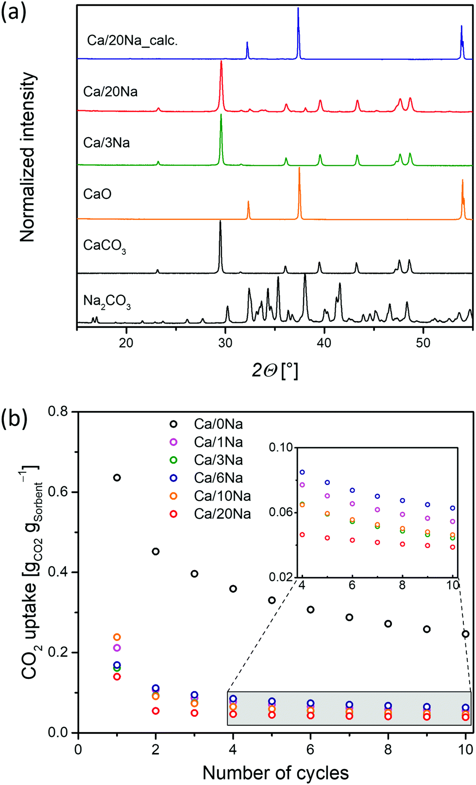 | ||
| Fig. 1 (a) XRD patterns of CaO-based sorbents as prepared and calcined and Na2CO3 and CaCO3 references; (b) cyclic CO2 capture performance of ball-milled Ca/xNa (calcination at 900 °C in CO2-rich atmosphere; carbonation at 650 °C in 20 vol% CO2). | ||
Cyclic CO2 uptake
The cyclic CO2 uptake performance of the ball-mill derived Ca/xNa materials (Fig. 1b) was determined under gas atmospheres and temperatures close to that prevailing in the envisioned large-scale CaL process, i.e. the calcination step was performed at 900 °C in a CO2-rich atmosphere; and the carbonation at 650 °C in 20 vol% CO2 in N2. Ca/0Na (i.e. the pure ball-milled calcite) exhibited a relatively high initial CO2 uptake (0.65 gCO2 gsorbent−1), however, its CO2 uptake gradually decreased with cycle number and reached 0.29 gCO2 gsorbent−1 after 10 carbonation/calcination cycles. The decay in the CO2 capacity of unsupported CaO is due to the sintering-induced loss in pore volume owing to the low TT of CaCO3 of 533 °C.7 We observed that the addition of Na2CO3 to CaO (Ca/xNa, with x = 1, 3, 6 10 and 20) led to a dramatic drop in the CO2 uptake of the sorbents (Fig. 1b) when compared to pure CaO (Ca/0Na). For instance, the maximum CO2 uptake of Ca/1Na in the 1st cycle was only 0.21 gCO2 gsorbent−1, a value that is ca. three times lower compared to Ca/0Na (0.65 gCO2 gsorbent−1). After the 10th cycle, Ca/1Na showed a CO2 uptake of 0.05 gCO2 gsorbent−1, a value that is ca. six times lower compared to Ca/0Na. Increasing the Na2CO3 content deteriorated further the CO2 uptake of the sorbents; for example, Ca/20Na showed CO2 uptakes of 0.14 gCO2 gsorbent−1 and 0.04 gCO2 gsorbent−1 in the 1st and 10th cycle, respectively.Analysis of the temporally-resolved CO2 uptake curves (Fig. S6, ESI†) revealed an irreversible mass gain Δm after the calcination step (900 °C, CO2-rich atmosphere) for the Na2CO3-modified sorbents. The observed weight gain Δm indicates the incomplete regeneration of CaCO3 to CaO in the calcination step. On the other hand, the CO2 uptake curve of Ca/0Na showed no weight difference when calcined at 900 °C in a CO2-rich atmosphere (and in the initial calcination at 800 °C in N2). Moreover, the values of Δm determined are proportional to the Na content in the materials (Fig. S6, ESI†). This observation suggests the formation of a phase (i.e. a Ca–Na mixed phase) that does neither capture nor release CO2 under the conditions investigated. Further details about the presence and the nature of this phase is provided by SEM and Na K-edge XANES analyses (vide infra).
Additionally, temperature-programed carbonation/calcination experiments (TPC, 150 cm3 min−1, 20 vol% CO2 in N2, 50 to 1000 °C, 10 °C min−1) of Ca/0Na, Ca/1Na and Ca/20Na as well as the reference Na2CO3 were performed in a TGA (Fig. S7, ESI†). As expected, pure Na2CO3 showed no weight increase over the entire temperature range probed. At temperatures above 850 °C, i.e. temperatures exceeding the melting temperature of Na2CO3 (melting temperature, TM = 851 °C) a gradual weight loss was detected. This weigh loss was due to the slow decomposition of Na2CO3 into Na2O and CO2, in agreement with previous observations.28 Turning to Ca/0Na, the TPC experiment showed a broad peak of weight gain with a maximum at ca. 570 °C due to the carbonation of CaO. The weight increase was followed by a rapid weight loss due to the decomposition of CaCO3 starting at 800 °C. Interestingly, the addition of Na2CO3 to CaO changed dramatically the sorbent's TPC curve profile. The Na2CO3-modified sorbents showed a lower CO2 uptake at intermediate temperatures (T < 700 °C), while the onset temperature for carbonation was not affected by the addition of Na2CO3 (Fig. S7, ESI†). The broad shoulder at intermediate temperatures was followed first by a narrow, sharp peak at T ≈ 750 °C, and secondly by a weight loss corresponding to the decomposition of CaCO3. Increasing the Na2CO3 content shifted the maximum of the carbonation peak towards higher temperatures, i.e. 770 °C for Ca/1Na and 785 °C for Ca/20Na (Fig. S7, ESI†). In contrast to pure Na2CO3, the Na2CO3-modified sorbents showed no weight loss at high temperatures, indicating the absence of Na2CO3 decomposition. We hypothesize that this was due to the formation of a stable Ca–Na mixed phase in CO2-containing atmospheres (vide infra).
Morphological characterization of the calcined sorbents
To understand the effect of the addition of Na2CO3 on the sorbents’ microstructure and sintering characteristics, XRD, SEM and N2-physisorption experiments were performed on the calcined materials (initial calcination at 800 °C in N2). After calcination in N2 at 800 °C, the average particle size remained largely unchanged (0.4 ± 0.1 μm, Fig. 2a and b) in Ca/0Na. We also observed an increase in the surface area and pore volume of Ca/0Na to, respectively, 16 m2 g−1 and 0.13 cm3 g−1, (compared to 9 m2 g−1 and 0.04 cm3 g−1, before calcination), which can be explained by the release of CO2 during the decomposition of CaCO3 to CaO (XRD, Fig. 1a).29 Different to Ca/0Na, we observed a considerable increase in particle size due to particle coalescence for the Na2CO3-modified sorbents (Fig. 2a and c). For example, the particle size of Ca/1Na increased from 350 nm to ca. 1.3 μm, accompanied by a drastic decrease in surface area (from 10 to 2 m2 g−1) and pore volume (from 0.06 to 0.01 cm3 g−1). These measurements hint to a dramatic collapse of the sorbents’ microstructure (Fig. S5, ESI†).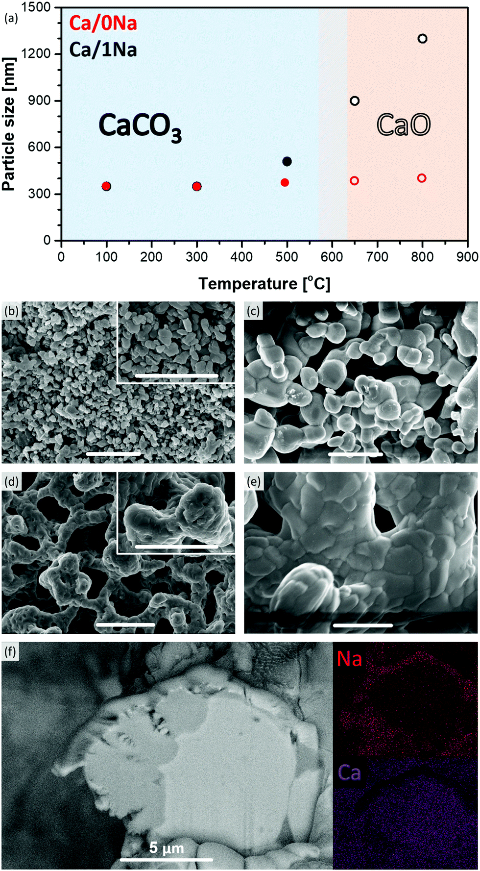 | ||
| Fig. 2 (a) The evolution of the particle size of Ca/0Na and Ca/1Na during the initial calcination step in N2, as determined by SEM, as a function of temperature; SEM images of (b) Ca/0Na and (c) Ca/1Na after the first calcination step; and (d) Ca/0Na and (e) Ca/1Na after the 10th carbonation step (the scale bar in (b–e) is equal to 2 μm); (f) cross sectional HR-SEM and EDX elemental mapping of Ca/20Na after the 10th carbonation step. | ||
The temperature dependence of the particle size of the sorbents was investigated in more detail and is shown in Fig. 2a and Fig. S8 (ESI†). Sintering of the Na2CO3-modified sorbents started at 500 °C and was likely promoted by the addition of Na2CO3 (TM = 851 °C, TT = 290 °C) that covered the surface of CaCO3 and/or CaO particles (Fig. 2f), thus, accelerating inter-particle coalescence. The XRD analysis of the calcined, Na2CO3-modified sorbents showed only Bragg peaks due to CaO (Fig. 1a, Ca/20Na_calc.), possibly due to the amorphous nature of the Na-containing phase.
The effect of sintering on the CO2 uptake of the pure CaO sorbent
To determine whether sintering (induced by the addition of Na2CO3) was the only reason for the appreciably decreased CO2 uptake performance of the Na2CO3-modified sorbents, we performed a series of control experiments. A set of pure CaCO3 sorbents was sintered by annealing them in a CO2 atmosphere at 750 °C for varying durations. The SEM micrographs as well as the surface area and pore volume measurements of the respective materials are presented in Fig. S9 and S10 (ESI†), respectively, revealing highly sintered materials with specific surface areas and pore volumes below 2 m2 g−1 and 0.02 m3 g−1, respectively (carbonated samples). However, similar to the as-prepared Ca/0Na and contrary to the Na2CO3-modified sorbents, calcination in N2 yielded a significant increase in both the surface area and pore volume (Fig. S10, ESI†). Additionally, we performed cyclic CO2 uptake measurements for the sintered sorbents and compared the performance to that of pure and Na2CO3-modified CaO (Fig. S11, ESI†). The sintered sorbents exhibited a worse CO2 uptake performance when compared to Ca/0Na, but they exceeded substantially the CO2 uptake performance of the Na2CO3-modified sorbents. Specifically, the most sintered, but Na2CO3-free sorbent that was annealed for 12 h had a CO2 uptake of 0.15 gCO2 gsorbent−1 in the 10th cycle compared to 0.05 gCO2 gsorbent−1 for Ca/1Na. These results indicate that sintering was one contributor explaining the poor CO2 uptake of Na2CO3-modified CaO, but not the only factor.Structure and morphology of the cycled sorbents
XRD analysis of cycled Ca/20Na (collected after the carbonation step) revealed that CaO was the major phase with only traces of CaCO3 present. This was in good agreement with the TGA-based CO2 uptake experiments, where a CO2 uptake of only 0.04 gCO2 gsorbent−1 was observed in the 10th cycle, corresponding to a CaO conversion of ca. 5%. Additional low-intensity peaks appeared in the diffraction pattern, which are tentatively attributed to the Ca–Na double carbonate Na2Ca(CO3)2 phase (in correlation with Na K-edge XAS, vide infra). SEM analysis of Ca/1Na after the 10th carbonation cycle (Fig. 2e) revealed an even higher degree of sintering compared to Ca/1Na after the initial calcination and cycled Ca/0Na (Fig. 2c and d, respectively). Despite the drastic, sintering-induced morphological changes, the low magnification SEM/EDX elemental mapping showed no indication of agglomeration of Na-containing phases (i.e. the Na maps still revealed a high dispersion of Na over the CaO/CaCO3 particles, Fig. S12, ESI†). To obtain a more detailed insight into the morphology of the material, a cross section of a Ca/20Na particle after the 10th carbonation step was prepared by FIB cutting and analyzed via high-resolution SEM/EDX. We observed that the CaO(CaCO3) particles were covered by a shell of a Na-rich phase (Fig. 2f), while the inner part of the particle was almost free of Na (Fig. 2f).XAS analysis: the nature of the Na containing phases in the cycled materials
To determine in more detail the nature of the Na-rich phase in the sorbents during the different steps of the CO2 capture process, Na K-edge XANES data were acquired. After the initial calcination step (800 °C, N2), the Na K-edge spectra of the sorbents matched perfectly the reference spectra of Na2CO3 (Fig. S14, ESI†). This observation, combined with Ca K-edge XAS results (vide infra, Fig. S13, ESI†), confirmed that all of the Na2CO3-modified sorbents consisted of a mixture of CaO and Na2CO3 after the initial calcination step and no Ca–Na mixed phase was present. The Na K-edge XANES spectra of all of the sorbents collected after the 10th carbonation step had a similar profile with a very characteristic shape of the XANES spectrum that was different from the XANES spectrum of pure Na2CO3 (Fig. 3). Specifically, all spectra possessed a pre-edge peak at ca. 1073.2 eV (−1.5 eV with respect to the absorption edge, feature A, Fig. 3), while Na2CO3 possessed a pre-edge feature at ca. 1073.5 eV (−1.2 eV with respect to the absorption edge). Additionally, contrary to the spectrum of Na2CO3 with a white line maximum at 1078.5 eV, the white line region of the Na2CO3-modified sorbents consisted of three defined features, i.e. B (ca. 1076.3 eV), C (ca. 1078 eV) and D (ca. 1080.6 eV, maximum intensity of the spectra) (Fig. 3). Notably, the obtained Na K-edge spectra of the Na2CO3-modified sorbents did not correspond to any previously reported XANES spectrum of Na-based materials. On the other hand, the spectra matched perfectly the Na2Ca(CO3)2 reference (P21ca space group,30 see XRD of the synthesized reference in Fig. S15, ESI†). The Na K-edge XAS spectrum of Na2Ca(CO3)2 is shown in Fig. 3 and, to the best of our knowledge, is reported here for the first time. A perfect match between the spectrum of Na2Ca(CO3)2 and the spectra of the cycled Na2CO3-modified sorbents (collected after the carbonation step) revealed the formation of the Ca–Na double carbonate (Na2Ca(CO3)2) under carbonation conditions (Fig. 3). Hence, the Na-rich phase that was observed by cross-sectional FIB-SEM (Fig. 2f) to cover the surface of CaO/CaCO3 particles was Na2Ca(CO3)2. Fig. 3 demonstrates that Na K-edge XANES can be used as a fingerprint to distinguish between Na in Na2CO3 or Na2Ca(CO3)2 environments. Being an element selective technique, XANES allowed us to study the Na environment in the materials, even when using relatively low Na contents (i.e. < 10 wt% Na2CO3); a composition for which XRD failed to provide sufficient information on the Na containing phases.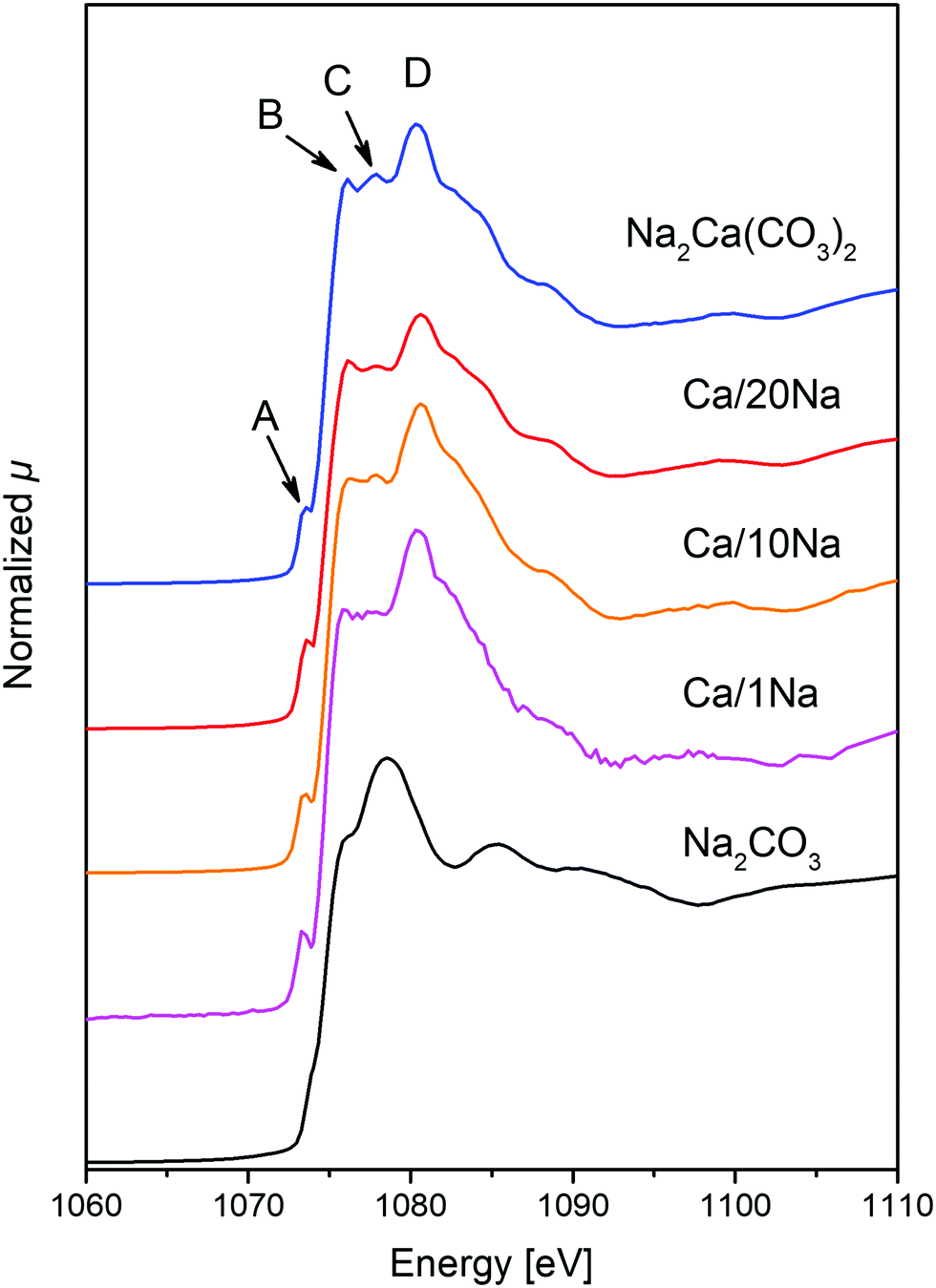 | ||
| Fig. 3 Na K-edge XANES spectra of Ca/1Na, Ca/10Na and Ca/20Na after 10th carbonation, as well as the references Na2CO3 and Na2Ca(CO3)2. | ||
Na K-edge XAS data were complemented by Ca K-edge XAS of the materials (Fig. S13, ESI†). The spectra of the as-prepared materials matched the reference calcite (CaCO3), revealing that no phase transformation (e.g. formation of aragonite CaCO3 polymorph)14 occurred during the ball-milling process (Fig. S13, ESI†). The spectra of the sorbents after the initial calcination step (800 °C, N2) matched the reference CaO. For the sample collected after the 10th carbonation cycle, and in line with XRD, the Ca K-edge spectra showed that the Ca was mainly in a CaO environment. Nonetheless, some features corresponding to CaCO3 could also be distinguished. These observations are in line with the TGA CO2 uptake experiments revealing a CO2 uptake below 0.05 gCO2 gsorbent−1 after 10 cycles. Since the majority of the Ca atoms was present in a CaO phase, the Ca K-edge spectra could not distinguish well between the different types of carbonate phases (i.e. CaCO3 and Na2Ca(CO3)2).
Discussion
After elucidation of the nature of the Ca–Na mixed phase, we carried out a control experiment to evaluate the performance of pure Na2Ca(CO3)2 under cyclic carbonation-calcination conditions (Fig. S16, ESI†). It was found that in the initial calcination in pure N2 Na2Ca(CO3)2 decomposed into CaO and Na2CO3 (at ca. 600 °C, as determined from the weight loss). In the following carbonation step a rapid weight gain was observed. No weight change was detected during the subsequent calcination step, confirming the stability of Na2Ca(CO3)2 during calcination at 900 °C in a CO2-rich atmosphere (Fig. S16, ESI†). This observation correlates well with the cyclic carbonation-calcination experiments of Ca/xNa as described above. In particular, the observed weight gain Δm by TGA under CO2 rich atmosphere with respect to the initial calcination step in N2 (Fig. S6, ESI†) can be explained by the formation of a Na2Ca(CO3)2 phase as revealed by XAS that was stable under both carbonation and calcination (in CO2 rich atmosphere) conditions. Such a weight increase was due to the reaction between CaO, Na2CO3 and CO2 forming Na2Ca(CO3)2. The melting point of Na2Ca(CO3)2 has been reported as Tm = 817 °C,31 which is significantly lower than the calcination temperature used here (900 °C). Therefore, during calcination (performed in a CO2-rich atmosphere) the Na2CO3-modified sorbent consisted of solid CaO covered by a molten Na2Ca(CO3)2 layer. Therefore, the presence of a molten salt layer promoted the sintering of the material.Overall, based on the results obtained here, the formation of Na2Ca(CO3)2 resulted in a dramatic reduction of the CO2 uptake performance of Na2CO3-modified CaO. This negative effect was attributed to (i) the formation of a molten Na2Ca(CO3)2 layer during calcination in CO2 rich atmosphere that promoted sintering, and (ii) the solidification of Na2Ca(CO3)2 during carbonation that resulted in a dense layer covering the unreacted (or partially reacted) CaO particles, thus hindering the further carbonation of CaO. Additionally, due to its low Tammann temperature (TT ≈ 270 °C), Na2Ca(CO3)2 further promoted the sintering of the CaO/CaCO3 particles.
Conclusions
To conclude, we demonstrated that the addition of 1 to 20 wt% Na2CO3 to CaO reduces dramatically the CO2 uptake performance of CaO from ca. 0.3 gCO2 gsorbent−1 for pure CaO to 0.05 gCO2 gsorbent−1 for Na2CO3 modified CaO after ten carbonation cycles. Combining TGA, XAS and FIB-SEM analyses allowed us to assign the formation of Na2Ca(CO3)2 as a key factor to explain the poor CO2 capture performance of Na2CO3-modified CaO. The poor CO2 capture performance of these materials is attributed to the presence of the low Tammann temperature phase Na2Ca(CO3)2 that is molten during the calcination step, thereby promoting sintering. During carbonation, a solid, dense layer of Na2Ca(CO3)2 covers the unreacted CaO particles, thus preventing its carbonation to CaCO3.Conflicts of interest
The authors declare that there is no conflict of interest regarding the publication of this article.Acknowledgements
The authors thank ScopeM for the use of their electron microscopy facilities. The Swiss Light Source (SLS, PSI, Villigen), through proposal 20160628, is acknowledged for provision of beamtime. Dr Felix Donat (ETH Zürich) is acknowledged for performing the ICP analyses and for his insightful comments. This project has received funding from the European Research Council (ERC) under the European Union's Horizon 2020 research and innovation programme grant agreement No. 819573. The Swiss National Science Foundation (SNSF, 200020_156015) is acknowledged for partial financial support.References
- World Energy Balances 2019, IEA, Paris, 2019.
- R. A. Betts, O. Boucher, M. Collins, P. M. Cox, P. D. Falloon, N. Gedney, D. L. Hemming, C. Huntingford, C. D. Jones, D. M. H. Sexton and M. J. Webb, Nature, 2007, 448, 1037–1041 CrossRef CAS.
- G. T. Rochelle, Science, 2009, 325, 1652–1654 CrossRef CAS.
- K. Veltman, B. Singh and E. G. Hertwich, Environ. Sci. Technol., 2010, 44, 1496–1502 CrossRef CAS.
- N. A. Fine, P. T. Nielsen and G. T. Rochelle, Environ. Sci. Technol., 2014, 48, 5996–6002 CrossRef CAS.
- A. MacKenzie, D. L. Granatstein, E. J. Anthony and J. C. Abanades, Energy Fuels, 2007, 21, 920–926 CrossRef CAS.
- A. M. Kierzkowska, R. Pacciani and C. R. Muller, ChemSusChem, 2013, 6, 1130–1148 CrossRef CAS.
- J. C. Abanades and D. Alvarez, Energy Fuels, 2003, 17, 308–315 CrossRef CAS.
- G. S. Grasa and J. C. Abanades, Ind. Eng. Chem. Res., 2006, 45, 8846–8851 CrossRef CAS.
- P. Sun, J. R. Grace, C. J. Lim and E. J. Anthony, AIChE J., 2007, 53, 2432–2442 CrossRef CAS.
- H. Lu, A. Khan, S. E. Pratsinis and P. G. Smirniotis, Energy Fuels, 2009, 23, 1093–1100 CrossRef CAS.
- M. Broda and C. R. Muller, Adv. Mater., 2012, 24, 3059–3064 CrossRef CAS.
- W. Liu, H. An, C. Qin, J. Yin, G. Wang, B. Feng and M. Xu, Energy Fuels, 2012, 26, 2751–2767 CrossRef CAS.
- A. Kurlov, M. Broda, D. Hosseini, S. J. Mitchell, J. Perez-Ramirez and C. R. Muller, ChemSusChem, 2016, 9, 2380–2390 CrossRef CAS.
- A. Armutlulu, M. A. Naeem, H. J. Liu, S. M. Kim, A. Kierzkowska, A. Fedorov and C. R. Muller, Adv. Mater., 2017, 29, 1702896 CrossRef.
- R. Han, J. Gao, S. Wei, Y. Su and Y. Qin, J. Mater. Chem. A, 2018, 6, 3462–3470 RSC.
- C. Ping, B.-Q. Feng, Y.-L. Teng, H.-Q. Chen, S.-L. Liu, Y.-L. Tai, H.-N. Liu and B.-X. Dong, RSC Adv., 2020, 10, 21509–21516 RSC.
- E. P. Reddy and P. G. Smirniotis, J. Phys. Chem. B, 2004, 108, 7794–7800 CrossRef CAS.
- C. Salvador, D. Lu, E. J. Anthony and J. C. Abanades, Chem. Eng. J., 2003, 96, 187–195 CrossRef CAS.
- V. Manovic, E. J. Anthony, G. Grasa and J. C. Abanades, Energy Fuels, 2008, 22, 3258–3264 CrossRef CAS.
- L. Huang, Y. Zhang, W. Gao, T. Harada, Q. Qin, Q. Zheng, T. A. Hatton and Q. Wang, Energy Technol., 2017, 5, 1328–1336 CrossRef CAS.
- A. Al-Mamoori, H. Thakkar, X. Li, A. A. Rownaghi and F. Rezaei, Ind. Eng. Chem. Res., 2017, 56, 8292–8300 CrossRef CAS.
- C. H. Lee, S. W. Choi, H. J. Yoon, H. J. Kwon, H. C. Lee, S. G. Jeon and K. B. Lee, Chem. Eng. J., 2018, 352, 103–109 CrossRef CAS.
- S. Brunauer, P. H. Emmett and E. Teller, J. Am. Chem. Soc., 1938, 60, 309–319 CrossRef CAS.
- E. P. Barrett, L. G. Joyner and P. P. Halenda, J. Am. Chem. Soc., 1951, 73, 373–380 CrossRef CAS.
- B. Ravel and M. Newville, J. Synchrotron Radiat., 2005, 12, 537–541 CrossRef CAS.
- R. J. Prado and A. M. Flank, Phys. Scr., 2005, T115, 165–167 CrossRef CAS.
- J.-W. Kim and H.-G. Lee, Metall. Mater. Trans. B, 2001, 32, 17–24 CrossRef.
- R. Barker, J. Appl. Chem. Biotechnol., 1973, 23, 733–742 CrossRef CAS.
- P. N. Gavryushkin, V. G. Thomas, N. B. Bolotina, V. V. Bakakin, A. V. Golovin, Y. V. Seryotkin, D. A. Fursenko and K. D. Litasov, Cryst. Growth Des., 2016, 16, 1893–1902 CrossRef CAS.
- R. H. Mitchell and B. A. Kjarsgaard, Can. Mineral., 2008, 46, 971–980 CrossRef CAS.
Footnote |
| † Electronic supplementary information (ESI) available. See DOI: 10.1039/d0cp04410e |
| This journal is © the Owner Societies 2020 |