 Open Access Article
Pseudo-ternary LiBH4·LiCl·P2S5 system as structurally disordered bulk electrolyte for all-solid-state lithium batteries†
Abdelouahab
El Kharbachi
 *ab,
Julia
Wind
ac,
Amund
Ruud
 c,
Astrid B.
Høgset
a,
Magnus M.
Nygård
a,
Junxian
Zhang
d,
Magnus H.
Sørby
*a,
Sangryun
Kim
e,
Fermin
Cuevas
 d,
Shin-ichi
Orimo
ef,
Maximilian
Fichtner
 bg,
Michel
Latroche
d,
Helmer
Fjellvåg
c and
Bjørn C.
Hauback
a
aInstitute for Energy Technology (IFE), P.O. Box 40, NO-2027 Kjeller, Norway. E-mail: magnus.sorby@ife.no
bHelmholtz Institute Ulm (HIU) Electrochemical Energy Storage, Helmholtzstr. 11, 89081 Ulm, Germany. E-mail: kharbachi@kit.edu
cCentre for Materials Science and Nanotechnology, University of Oslo, P.O. Box 1126, Blindern, NO-0318 Oslo, Norway
dUniv Paris Est Creteil, CNRS, ICMPE, UMR7182, F-94320, Thiais, France
eInstitute for Materials Research, Tohoku University, Sendai 980-8577, Japan
fWPI-Advanced Institute for Materials Research, Tohoku University, Sendai 980-8577, Japan
gInstitute of Nanotechnology, Karlsruhe Institute of Technology (KIT), P.O. Box 3640, 76021 Karlsruhe, Germany
First published on 28th April 2020
Abstract
The properties of the mixed system LiBH4–LiCl–P2S5 are studied with respect to all-solid-state batteries. The studied material undergoes an amorphization upon heating above 60 °C, accompanied with increased Li+ conductivity beneficial for battery electrolyte applications. The measured ionic conductivity is ∼10−3 S cm−1 at room temperature with an activation energy of 0.40(2) eV after amorphization. Structural analysis and characterization of the material suggest that BH4 groups and PS4 may belong to the same molecular structure, where Cl ions interplay to accommodate the structural unit. Thanks to its conductivity, ductility and electrochemical stability (up to 5 V, Au vs. Li+/Li), this new electrolyte is successfully tested in battery cells operated with a cathode material (layered TiS2, theo. capacity 239 mA h g−1) and Li anode resulting in 93% capacity retention (10 cycles) and notable cycling stability under the current density ∼12 mA g−1 (0.05C-rate) at 50 °C. Further advanced characterisation by means of operando synchrotron X-ray diffraction in transmission mode contributes explicitly to a better understanding of the (de)lithiation processes of solid-state battery electrodes operated at moderate temperatures.
Introduction
Substitution of the current liquid electrolytes by solid-state electrolytes (SSEs) is expected to be the next leap in lithium ion battery technology.1 The integration of SSEs in future batteries is motivated by the expected large energy density, improved safety and stability over a wide temperature range,2–5 hence exceeding the performances of carbonate or polymer-based (liquid, gel and/or solid) electrolytes.6–11 The study of complex hydride systems as SSEs has attracted the curiosity of the solid-state ionics community since the discovery of the fast Li-ionic conduction in LiBH4, and closo-decaborates.12–19 A recent work has been reported by Kim et al.20 for the system, 0.7Li(CB9H10)–0.3Li(CB11H12), showing excellent stability against lithium metal and high conductivity of 6.7 × 10⁻³ S cm−1 at 25 °C. This electrolyte system enabled the fabrication of an all-solid-state lithium–sulfur battery with high energy density and cycling stability. Such low-density materials may have a direct impact on the next-generation batteries.The lithium ionic conduction in the system 90LiBH4–10P2S5 has been studied by Unemoto et al.21 and fast ionic conductivities were reported for heat-treated samples. The annealing leads to partial decomposition accompanied with loss of B/H species. The addition of LiBH4 or Li(BH4)0.75I0.25 to Li2S–P2S5 has been shown to increase the ionic conductivities near room temperature (RT) and improve the contact at the electrode/electrolyte interfaces during battery tests.21–23
The structural, thermodynamic and ionic properties of LiBH4 and its phase transition (orthorhombic to hexagonal, Ttrs = 113 °C)24–29 involves a reorientation of the tetrahedral [BH4−] anions and shortened Li–Li distances with high Li-ionic conduction.15,30,31 The Li-ion conducting hexagonal phase can be stabilized at RT by partly substituting [BH4−] with the halides Br− or I−.32–35 Orthorhombic Li(BH4)1−xClx, on the other hand, is metastable at RT and decomposes to a mixture of LiBH4 and LiCl at a rate which depends on composition. This has been explained by the smaller ionic radius of Cl− in comparison to I− and Br−.36,37 The use of a halide-substituted phase such as Li(BH4)0.75I0.25 has shown possible solid–electrolyte interface evolving toward the cathode materials during long-term cycling.38 Although the ionic conductivity of Li(BH4)0.75I0.25 is several orders of magnitude higher than that of LiBH4,33,39 the study of composite systems containing the low-T modification ortho-LiBH4 can be of interest for the design of future batteries,40 as this latter phase shows pressure-dependent flexible mechanical properties, strain-induced diffusion activation energy and formation of a stable interface with many promising electrodes.41–48
Here, we report our recent findings regarding the ionic conductivity of the pseudo-ternary system LiBH4–LiCl–P2S5 for solid-state battery electrolytes. The prepared electrolytes are investigated with respect to their structural and ionic properties and cycling stability in lithium metal cells. Thanks to the low scattering of the bulk electrolyte, a pioneering operando synchrotron X-ray diffraction study is presented to obtain a better understanding of the processes in the assembled solid-state batteries under operation at moderate temperatures.
Experimental
Materials synthesis and characterization
LiBH4 (95%), LiCl (99.9%) and P2S5 (99%) were purchased from Sigma-Aldrich and stored in an Ar-filled glove box (<1 ppm O2, H2O). LiBH4 and LiCl in 3![[thin space (1/6-em)]](https://www.rsc.org/images/entities/char_2009.gif) :
:![[thin space (1/6-em)]](https://www.rsc.org/images/entities/char_2009.gif) 1 molar ratio were ball-milled for 5 hours using a Fritsch Pulverisette 6 (P6) planetary ball-mill with stainless steel vials and balls (ball-to-powder ratio 40
1 molar ratio were ball-milled for 5 hours using a Fritsch Pulverisette 6 (P6) planetary ball-mill with stainless steel vials and balls (ball-to-powder ratio 40![[thin space (1/6-em)]](https://www.rsc.org/images/entities/char_2009.gif) :
:![[thin space (1/6-em)]](https://www.rsc.org/images/entities/char_2009.gif) 1, 370 rpm). Crystalline P2S5 was then added to this mixture and ball-milled with Spex-mill for 3 hours with the same conditions. All the preparations were carried out in the glove box. Two compositions (mole ratios) were prepared:
1, 370 rpm). Crystalline P2S5 was then added to this mixture and ball-milled with Spex-mill for 3 hours with the same conditions. All the preparations were carried out in the glove box. Two compositions (mole ratios) were prepared:
80(3LiBH4·LiCl)·20P2S5: called LCPS20
90(3LiBH4·LiCl)·10P2S5: called LCPS10.
Synchrotron radiation powder X-ray diffraction (SR-PXD) patterns were obtained at the Swiss-Norwegian Beamlines (SNBL, BM31), ESRF, Grenoble, France with a Dexela 2-dimensional CMOS detector,49 and a wavelength of 0.3123 or 0.4943 Å calibrated against a NIST Si standard. The samples were contained in 0.5 mm boronglass capillaries that were rotated 90 degrees during the 30 second exposure. The sample-detector distance was 345.97 mm. 1D data were obtained by integration of the 2D diffraction patterns with the program Bubble.50 Phase identification from the PXD data was performed using the DIFFRAC.SUITE EVA software with the PDF-4 database.
Operando SR-PXD data were collected at the SNBL BM01B. All-solid-state batteries were assembled into a dedicated electrochemical cell of Swagelok-type with Kapton windows.51 Cells were heated to a temperature of 60 °C (in-house built heater) and allowed to equilibrate for 60 minutes. Cycling was performed using a Bat-Small battery cycler (Astrol) with an applied C-rate current of C/10. All profile fittings and Rietveld refinements were performed within TOPAS V5 (Bruker AXS). For SR-PXD patterns, background (Chebychev polynomial), zero-shift, peak-profile parameters, unit cell parameters and scale factor were refined. Broad background features (due to amorphous contributions) were fitted with Gaussian peaks (refined position and broadening). During sequential refinement across all collected operando patterns, only unit cell dimensions and scale factors were refined. All the samples for PXD were assembled and sealed under Ar in the glove box.
TGA/DSC thermal analysis was performed with a Netzsch STA 449 F3 Jupiter instrument in the 25–400 °C temperature range. Samples were measured with Al crucibles at a heating rate of 10 °C min−1 and 50 mL min−1 Ar flow. Characterizations of the vibrational states were performed by Raman spectroscopy (Nicolet Almega-HD, Thermo Scientific) using a dedicated cell without any air exposure.
Electrochemical analysis and battery tests
Ionic conductivities were determined by electrochemical impedance spectroscopy (EIS). The powder samples were pressed into 8 mm diameter pellet of <2 mm thickness by a uniaxial press at around 240 MPa inside the glove box at ambient temperature. The pellets were sandwiched by lithium foils as non-blocking electrodes and sealed in a homemade cell without air contact.52 The cells were placed in the heating jacket and the EIS were carried out over a frequency range from 1 MHz to 4 Hz using a HIOKI 3532-80 from RT to 150 °C in heating and cooling runs. A program-interface allows the automatic control of the stability of each measurement at fixed temperature in equilibrium conditions.The measured impedance spectra were analyzed by equivalent circuits using the ZView2 software (Scribner Associates Inc.). Additional EIS measurements and cyclic voltammetry were performed using Bio-Logic® VSP multi-channel potentiostat, either in coin cells or a homemade cell described elsewhere.53
For battery tests, TiS2 (99.9%, Sigma-Aldrich) and Li foil were used as working and counter/reference electrode, respectively. The TiS2 and the prepared SE powders in 2![[thin space (1/6-em)]](https://www.rsc.org/images/entities/char_2009.gif) :
:![[thin space (1/6-em)]](https://www.rsc.org/images/entities/char_2009.gif) 3 mass ratio were hand mixed in an agate mortar inside the glove box. The obtained mixture was used as the electrode composite. Around 6 mg of this composite and 30 mg of the SE were introduced in a 10 mm die set and uniaxially pressed together at 240 MPa. A Li foil was placed on the opposite side of the electrode composite before the pellet was inserted in a coin cell. The assembled cells were moved out of glovebox and annealed at 60 °C for 5 h before testing at a cycling station from Bio-Logic Instrument in a temperature-controlled cabinet at 50 °C.
3 mass ratio were hand mixed in an agate mortar inside the glove box. The obtained mixture was used as the electrode composite. Around 6 mg of this composite and 30 mg of the SE were introduced in a 10 mm die set and uniaxially pressed together at 240 MPa. A Li foil was placed on the opposite side of the electrode composite before the pellet was inserted in a coin cell. The assembled cells were moved out of glovebox and annealed at 60 °C for 5 h before testing at a cycling station from Bio-Logic Instrument in a temperature-controlled cabinet at 50 °C.
Results and discussion
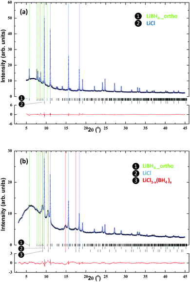
Fig. 1 presents the SR-PXD patterns of ball milled 3LiBH4–LiCl and the prepared LCPS10 sample. For the 3LiBH4–LiCl sample the pattern shows Bragg peaks from LiBH4 and LiCl without any noticeable formation of the Li(BH4)1−xClx phase (Fig. 1a), in agreement with previous studies of the LiBH4–LiCl pseudo-binary system.36,37,52,54 The phase composition estimated from Rietveld refinements is 65 mole% of LiBH4 and 35 mole% of LiCl. This difference compared to the nominal composition before ball-milling could be attributed to the presence of an amorphous part and/or a metastable phase at low content. No additional peaks are present. On the other hand, the addition of P2S5 to this system and further ball-milling (sample LCPS10) leads to almost complete disappearance of LiBH4 peaks (Fig. 1b) and increased diffuse scattering from an amorphous phase. However, the peaks from the LiCl phase remain intense. In addition, a set of broader peaks, most prominent at lower angles, is observed. Being located at slightly lower angles compared to the LiCl phase, these can be attributed to a LiCl-like structure with larger unit cell dimensions, such as a solid solution of LiCl1−x(BH4)x, with or without PS4 anions.Previous studies have established a Vegards’ law behavior for LiCl1−x(BH4)x,55,56 and the unit cell parameter of a = 5.385(2) Å for the present phase (compared to 5.1419(1) Å for pure LiCl) indicates a composition of LiCl0.6(BH4)0.4. Based on this assumption, the estimated crystalline phase fractions in sample LCPS10 are 26.8 mole% LiCl, 66.7 mole% LiCl0.6(BH4)0.4 and 6.5 mole% LiBH4. Possible structural trends for compositions with varied P2S5 contents (5–50 mol%) have been investigated (Fig. S1 in ESI†). For LCPS20 the collected PXD pattern is dominated by diffuse scattering from an amorphous phase with minor Bragg peaks of LiCl. At higher P2S5 contents, only diffuse scattering is observed.
The ionic conductivities of both LCPS10 and LCPS20 were measured in the temperature range RT–150 °C (Fig. 2a and b). The two samples show comparable conductivity at RT, in the order of 10−5 S cm−1. While the conductivity for LCPS20 does not change during the first 2 cycles, the conductivity for LCPS10 increases after the 1st heating and becomes stable for the next cooling/heating/cooling sequences.
For LCPS20, the measurements show stable conductivity during temperature cycling with almost no hysteresis. The LCPS10 SSE presents a slight hysteresis in the second heating/cooling run. With exception of the first heating on LCPS10, the conductivity plots versus 1/T are linear, thus indicating that no phase transition between orthorhombic and hexagonal LiBH4 is taking place. The assumption of the elimination of the phase transition in LiBH4 by anion substitution agrees with previously reported studies on halide substitution.32,57 Worth mentioning that the resulted powders are whitish for LCPS10 and brownish for LCPS20. We suspect the formation of a new dominant amorphous phase in LCPS20 during synthesis (Fig. S1 in ESI†), which is stable during heating. In contrast, structural changes for LCPS10 occur during heat treatment. Although the conductivity range for LCPS20 tends to fall in the same order of magnitude as for the reported one for the Argyrodite Li6PS5Cl0.83(BH4)0.17 with low BH4/Li ratio,58 however owing to the differences in composition, structure and materials processing and synthesis, the comparison becomes tricky.
Furthermore, this ionic behavior reflects the structural difference between the two SSE materials. For LCPS10, the final conductivities are significantly higher than the reported values for LiBH4 and LiBH4/LiCl pseudo-binary system at the same temperatures.22,52,59 Correspondingly, the obtained conductivities follow an Arrhenius trend (Fig. 2c) according to the relation:  , where σ is the ionic conductivity and Ea the activation energy. The calculated Ea for LCPS10 and LCPS20 SSEs are 0.40(2) eV and 0.49(2) eV respectively. Overall, a remarkable ionic conductivity of about 10−3 S cm−1 near RT is reached for LCPS10. This result may have a direct implication on the development of a new generation of solid-state batteries with high-energy density and a wide temperature range which cannot be achieved by current commercial60 carbonate-based liquid electrolytes.61,62 Based on this fact, the following investigations will focus on the LCPS10 sample.
TGA/DSC thermal analysis (Fig. 3) was carried out for LCPS10 samples, both as-milled and after annealing at 150 °C for 8 hours under H2 atmosphere in a closed vessel. The ball-milled sample displays two small events at 60 °C (endothermic) and 105 °C (exothermic), the second being accompanied with 2.5% mass loss. However, the pre-annealed sample at 150 °C is stable in this temperature range and showing a mass loss only above 200 °C. Additional exothermic event can be seen at 280–300 °C.
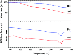 | ||
| Fig. 3 TGA (top) and DSC (bottom) analysis for (a) ball-milled LCPS10 and (b) annealed LCPS10 at 150 °C. | ||
The SR-PXD patterns of LCPS10 collected during heating from RT to 150 °C with a rate of 10 °C min−1 are shown in Fig. 4. At RT before heating, the sample shows Bragg peaks from LiCl, a solid solution-like phase LiCl1−x(BH4)x (Fig. 1b) and pronounced diffuse scattering from amorphous components. During heating of the sample, a gradual structural transformation is observed, in excellent agreement with conductivity and DSC measurements. LiCl Bragg peaks disappear and the sample undergoes total amorphization at around 80 °C, which seems not related to mass loss according to TGA. Based on DSC and PXD analysis, it seems the high-T LiCl1−x(BH4)x phase with higher free energy is playing a key role in inducing this transformation in the presence of 10 mole% P2S5 and facilitates thermodynamically the formation of the final material. Excess P2S5 would lead to a Li-poor phase with lower conductivities (Fig. S1, ESI† and Fig. 2b).
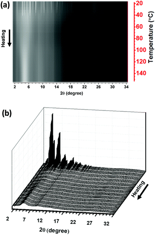 | ||
| Fig. 4 2D (a) and 3D (b) views of the SR-PXD of the LCPS10 as function of temperature from RT to 150 °C (10 °C min−1; λ = 0.3123 Å). The linear heating scale is shown on the right Y-axis in (a). | ||
Besides the observed irreversibility of the process upon cooling down to RT, the TGA/DSC analysis does not show any significant thermal event for the annealed LCPS10 in the temperature range RT–150 °C, indicating a good thermal stability for high-T applications.
Raman spectroscopy has been carried out to elucidate the chemical environment of the BH4, PS4 and/or P2S6 groups in the LCPS10 and LCPS20 samples. The obtained spectra, compared to those of the starting materials 3LiBH4–LiCl and P2S5, are shown in Fig. 5. 3LiBH4–LiCl shows the same [BH4−] vibrational modes as pure LiBH4,22,23 but with broader and less well-defined bands in accordance with previous works.34,35 The two characteristic bands (stretching and bending) of pure LiBH4 can be seen in the 3000–400 cm−1 spectral region. The stretching band (1350–1000 cm−1) is split across a wide region owing to the presence of an overtone (3νL, 1231 cm−1).63,64 The mixing with P2S5 at different proportions leads to weaker intensities and disappearance of some features of the [BH4−] vibrational modes. However, the two main bands are still present, and the lowered intensities may suggest a decrease of the symmetry and a modified [BH4−] geometry. The most reported [PS43−] entity is characterized by a wide peak at 542 cm−1 and is clearly observed in the spectrum of the LCPS10 sample.65
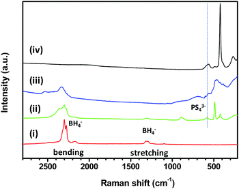 | ||
| Fig. 5 Raman spectra region 2800–210 cm−1 of (i) 3LiBH4–LiCl, (ii) LCPS10, (iii) LCPS20 and (iv) P2S5 samples. | ||
The peak attributed to the [PS43−] group in LCPS20 becomes broad and slightly shifted. This agrees with higher configurational disorder. The [P2S64−]-anions may be present as indicated by the band at 385 cm−1. However, at low wavenumbers, Raman spectra confirm explicitly the presence of [PS43−] moieties represented by the three peaks at 267, 422 and 564 cm−1 in the LCPS10 sample,16,59,65 as well as an indication of higher structural disorder (amorphisation) for LCPS20 in agreement with the PXD analysis (Fig. S1, ESI†). The peak around 500 cm−1 can be linked to the S–S bond and the shoulder at 2385 cm−1 in LCPS10 is attributable to a feature of the stretching band which agree with the fact that [BH4−] ions may exist in different chemical environments,22 likely formed from the incorporation of [PS43−] ions. Based on the observed DSC event described above in the RT–150 °C temperature range (Fig. 3), the observed irreversible transformation in the SR-PXD suggests a subtle rearrangement of the BH4 groups of the high-T hexagonal LiCl1−x(BH4)x phase in the presence of [PS43−] anions.37 This assumption is corroborated by Raman spectroscopy where the BH4 and PS4 groups may co-exist in close chemical proximity i.e. the same phase. However, it is not possible from the present diffraction and Raman data to establish the crystal structure of the new formed phase(s) in LCPS10 electrolyte.
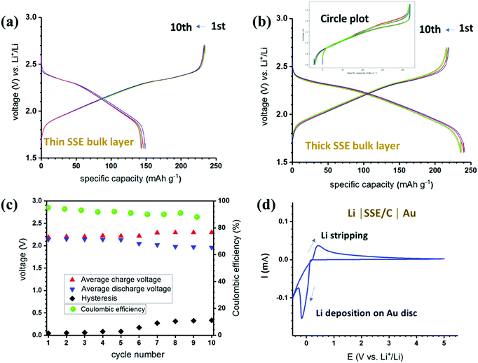
Further electrochemical characterizations were focused on the sample LCPS10 in order to obtain more details on the behaviour in the battery cell. The study is supplemented by electrochemical stability measurements and battery tests at 50 °C. Prior to being used in a battery cell, the SE powders were homogenized by heat treatment at 150 °C for 24 h in reducing atmosphere (2 MPa H2). Using this optimized SSE, battery tests were carried out in a two-electrode Li-ion cells using TiS2 cathode and Li anode (CE/ref). TiS2 adopts a trigonal layered structure (space group P![[3 with combining macron]](https://www.rsc.org/images/entities/char_0033_0304.gif) m1, no. 164) with the initial lattice parameters a = b = 3.4073 and c = 5.6953. Up to one Li can be inserted assuming the complete reaction: yLi + TiS2 → LiyTiS2.66 Having good electronic conductivity,67 this electrode can be used without further carbon additions; hence reducing the number of interface issues that can be encountered in solid-state batteries.68,69Fig. 6a and b shows the galvanostatic charge/discharge cycling at rate C/20 (10 cycles) for two cells with thin (300 μm) and thick (600 μm) bulk SSE. Both cells show remarkable cyclability and stability over several cycles. Note that the electrolyte presents some ductility, such a property could be suitable to compensate the electrode volume changes as a major issue of solid-state batteries.
m1, no. 164) with the initial lattice parameters a = b = 3.4073 and c = 5.6953. Up to one Li can be inserted assuming the complete reaction: yLi + TiS2 → LiyTiS2.66 Having good electronic conductivity,67 this electrode can be used without further carbon additions; hence reducing the number of interface issues that can be encountered in solid-state batteries.68,69Fig. 6a and b shows the galvanostatic charge/discharge cycling at rate C/20 (10 cycles) for two cells with thin (300 μm) and thick (600 μm) bulk SSE. Both cells show remarkable cyclability and stability over several cycles. Note that the electrolyte presents some ductility, such a property could be suitable to compensate the electrode volume changes as a major issue of solid-state batteries.
The first cell (Fig. 6a) shows lower capacity during discharge compared to the charge process. Since this seems to be stable and reproducible, one could attribute such behavior to the increase of the stress in the working electrode during lithiation as the cells were pressed at the same pressure. In fact, thin bulk cells may allow cycling at higher rates, but for developments and applications the engineering of the cell configuration need to be optimized. For the second cell (Fig. 6b and c), the capacity retention presents 93% of the theoretical capacity of TiS2 (∼239 mA h g−1) after 10 cycles, while the Coulombic efficiency remains stable during cycling. Based on the average voltages, the discharge–charge hysteresis is significantly smaller than usual. Cyclic voltammogram of the SSE is presented in Fig. 6d, and the stripping/platting of Li can be observed around 0 V with successive oxidation and reduction of the Li metal.
A layer of mixed SSE–carbon black has been added to ensure better adhesion to the Au surface. At low voltage, a possible side reaction may be due to the presence of carbon and/or impurities. However, at high voltage, the “active material-free” LCPS10 electrolyte shows an electrochemical window up to 5 V.
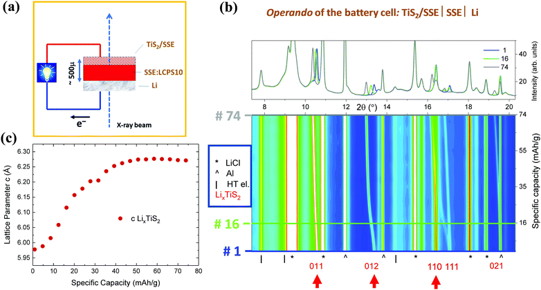
Fig. 7 shows operando SR-PXD patterns of the battery cell during the discharge presented in Fig. 6b. The sketch of the experimental set-up is shown in Fig. 7a. The first diffraction pattern (before cycling starts) indicates that the main contributions are LiCl and TiS2 in addition to the current collector (Al). Significant shifts in the Bragg peaks, corresponding to expansion of the TiS2 electrode (LiyTiS2) along the c-axis during lithiation can be observed. Miller indices of the main reflections as well as arrows indicating the reflections with the main changes are shown in Fig. 7b.
The corresponding change in the lattice parameter c as a function of the discharge capacity is shown in Fig. 7c. In fact, the TiS2 expansion occurs only in c direction with no changes in a direction, due to the layered structure of the material. As expected, no changes in the bulk SSE itself can be observed – the SSE peaks remain stable throughout the operando experiment. With the present setup, no additional potential side reactions and/or interface formations and evolutions can be detected. Owing to beam time constraints, the cells were only lithiated partially.
Data for the re-charge of the cell, showing the corresponding contraction along the c-axis for LiyTiS2 during the delithiation process, are summarized in Fig. S2 (ESI†). Accordingly, one can witness a change in the expansion along the c-axis for the LiyTiS2 solid solution but no change in the bulk electrolyte material itself. The observed instabilities for the c parameters during delithiation (Fig. S2b, ESI†), may be attributed to inhomogeneities and segregations, which could reflect changes in the intrinsic properties between the charged and discharged states.
Conclusions
A pseudo-ternary LiBH4–LiCl–P2S5 solid-state electrolyte is reported in this study. The as-milled materials showed low ionic conductivity. However, a high ionic conductivity of ∼10−3 S cm−1 with an activation energy of 0.40(2) eV was measured at RT after heat treatment at 150 °C. This solid-state electrolyte has the approximate nominal composition (LiBH4)0.73·(LiCl)0.24·(P2S5)0.03 and usable conductivity range for applications in solid state batteries. Structural analysis and characterization of this material suggest that BH4 and PS4 groups may belong to the same structural unit, while Cl ions substitution by PS4 may occur in this structure when small amounts of P2S5 are added. During the preliminary electrochemical tests, this new SSE is stable in contact with Li metal and battery tests using TiS2 cathode show notable cyclability and reversibility. Furthermore, thanks to the low scattering of the bulk electrolyte based on light-weight borohydride, we demonstrate the possibility of operando PXD analysis in transmission mode of a solid-state battery, where (de)lithiation processes can be followed during the battery cycling tests.Conflicts of interest
There are no conflicts to declare.Acknowledgements
This work is financially supported by Research Council of Norway under the program ENERGIX, Project no. 244054, LiMBAT. The authors also acknowledge the Research Council of Norway (Grant agreement SELiNaB-255441) for financial support. We acknowledge the skillful assistance from the staff of SNBL at ESRF, Grenoble, France. This work contributes to the research performed at CELEST (Center for Electrochemical Energy Storage Ulm-Karlsruhe).References
- A. Mauger, C. M. Julien, A. Paolella, M. Armand and K. Zaghib, Materials, 2019, 12, 3892 CrossRef PubMed.
- M. Armand and J. M. Tarascon, Nature, 2008, 451, 652–657 CrossRef CAS PubMed.
- J. B. Goodenough, J. Solid State Electrochem., 2012, 16, 2019–2029 CrossRef CAS.
- E. Quartarone and P. Mustarelli, Chem. Soc. Rev., 2011, 40, 2525–2540 RSC.
- N. Legrand, B. Knosp, P. Desprez, F. Lapicque and S. Raël, J. Power Sources, 2014, 245, 208–216 CrossRef CAS.
- C. Masquelier, Nat. Mater., 2011, 10, 649–650 CrossRef CAS PubMed.
- N. Kamaya, K. Homma, Y. Yamakawa, M. Hirayama, R. Kanno, M. Yonemura, T. Kamiyama, Y. Kato, S. Hama, K. Kawamoto and A. Mitsui, Nat. Mater., 2011, 10, 682–686 CrossRef CAS PubMed.
- M. H. Braga, N. S. Grundish, A. J. Murchison and J. B. Goodenough, Energy Environ. Sci., 2017, 10, 331–336 RSC.
- A. Lecocq, G. G. Eshetu, S. Grugeon, N. Martin, S. Laruelle and G. Marlair, J. Power Sources, 2016, 316, 197–206 CrossRef CAS.
- Y. Wang, W. D. Richards, S. P. Ong, L. J. Miara, J. C. Kim, Y. Mo and G. Ceder, Nat. Mater., 2015, 14, 1026–1031 CrossRef CAS PubMed.
- A. El kharbachi, Y. Hu, M. H. Sørby, J. P. Mæhlen, P. E. Vullum, H. Fjellvåg and B. C. Hauback, Solid State Ionics, 2018, 317, 263–267 CrossRef CAS.
- B. Didier, N. Angeloclaudio, S. Dadi, T. M. Eggenhuisen, M. H. W. Verkuijlen, S. Suwarno, V. Tejs, A. P. M. Kentgens and P. E. de Jongh, Adv. Funct. Mater., 2015, 25, 184–192 CrossRef.
- R. Mohtadi and S.-i. Orimo, Nat. Rev. Mater., 2016, 2, 16091 CrossRef.
- P. E. de Jongh, D. Blanchard, M. Matsuo, T. J. Udovic and S. Orimo, Appl. Phys. A: Mater. Sci. Process., 2016, 122, 251 CrossRef.
- M. Matsuo and S.-i. Orimo, Adv. Energy Mater., 2011, 1, 161–172 CrossRef CAS.
- Y. S. Choi, Y.-S. Lee, K. H. Oh and Y. W. Cho, Phys. Chem. Chem. Phys., 2016, 18, 22540–22547 RSC.
- J. A. Teprovich, H. Colon-Mercado, A. L. Washington Ii, P. A. Ward, S. Greenway, D. M. Missimer, H. Hartman, J. Velten, J. H. Christian and R. Zidan, J. Mater. Chem. A, 2015, 3, 22853–22859 RSC.
- W. S. Tang, M. Matsuo, H. Wu, V. Stavila, W. Zhou, A. A. Talin, A. V. Soloninin, R. V. Skoryunov, O. A. Babanova, A. V. Skripov, A. Unemoto, S.-I. Orimo and T. J. Udovic, Adv. Energy Mater., 2016, 6, 1502237 CrossRef.
- S. Kim, N. Toyama, H. Oguchi, T. Sato, S. Takagi, T. Ikeshoji and S.-i. Orimo, Chem. Mater., 2018, 30, 386–391 CrossRef CAS.
- S. Kim, H. Oguchi, N. Toyama, T. Sato, S. Takagi, T. Otomo, D. Arunkumar, N. Kuwata, J. Kawamura and S.-i. Orimo, Nat. Commun., 2019, 10, 1081 CrossRef PubMed.
- A. Unemoto, H. Wu, T. J. Udovic, M. Matsuo, T. Ikeshoji and S.-i. Orimo, Chem. Commun., 2016, 52, 564–566 RSC.
- A. Yamauchi, A. Sakuda, A. Hayashi and M. Tatsumisago, J. Power Sources, 2013, 244, 707–710 CrossRef CAS.
- A. El kharbachi, Y. Hu, K. Yoshida, P. Vajeeston, S. Kim, M. H. Sørby, S.-i. Orimo, H. Fjellvåg and B. C. Hauback, Electrochim. Acta, 2018, 278, 332–339 CrossRef CAS.
- J. P. Soulié, G. Renaudin, R. Cerný and K. Yvon, J. Alloys Compd., 2002, 346, 200–205 CrossRef.
- Y. Filinchuk, D. Chernyshov and R. Cerny, J. Phys. Chem. C, 2008, 112, 10579–10584 CrossRef CAS.
- A. El Kharbachi, E. Pinatel, I. Nuta and M. Baricco, CALPHAD: Comput. Coupling Phase Diagrams Thermochem., 2012, 39, 80–90 CrossRef CAS.
- P. Vajeeston, P. Ravindran, A. Kjekshus and H. Fjellvåg, J. Alloys Compd., 2005, 387, 97–104 CrossRef CAS.
- T. Ikeshoji, E. Tsuchida, K. Ikeda, M. Matsuo, H.-W. Li, Y. Kawazoe and S.-i. Orimo, Appl. Phys. Lett., 2009, 95, 221901 CrossRef.
- M. Matsuo, Y. Nakamori, S.-i. Orimo, H. Maekawa and H. Takamura, Appl. Phys. Lett., 2007, 91, 224103 CrossRef.
- T. Ikeshoji, E. Tsuchida, T. Morishita, K. Ikeda, M. Matsuo, Y. Kawazoe and S.-i. Orimo, Phys. Rev. B: Condens. Matter Mater. Phys., 2011, 83, 144301 CrossRef.
- V. Epp and M. Wilkening, Phys. Rev. B: Condens. Matter Mater. Phys., 2010, 82, 020301 CrossRef.
- H. Maekawa, M. Matsuo, H. Takamura, M. Ando, Y. Noda, T. Karahashi and S.-i. Orimo, J. Am. Chem. Soc., 2009, 131, 894–895 CrossRef CAS PubMed.
- R. Miyazaki, T. Karahashi, N. Kumatani, Y. Noda, M. Ando, H. Takamura, M. Matsuo, S. Orimo and H. Maekawa, Solid State Ionics, 2011, 192, 143–147 CrossRef CAS.
- L. H. Rude, E. Groppo, L. M. Arnbjerg, D. B. Ravnsbæk, R. A. Malmkjær, Y. Filinchuk, M. Baricco, F. Besenbacher and T. R. Jensen, J. Alloys Compd., 2011, 509, 8299–8305 CrossRef CAS.
- L. H. Rude, O. Zavorotynska, L. M. Arnbjerg, D. B. Ravnsbæk, R. A. Malmkjær, H. Grove, B. C. Hauback, M. Baricco, Y. Filinchuk, F. Besenbacher and T. R. Jensen, Int. J. Hydrogen Energy, 2011, 36, 15664–15672 CrossRef CAS.
- M. Matsuo, H. Takamura, H. Maekawa, H.-W. Li and S.-i. Orimo, Appl. Phys. Lett., 2009, 94, 084103 CrossRef.
- L. M. Arnbjerg, D. B. Ravnsbæk, Y. Filinchuk, R. T. Vang, Y. Cerenius, F. Besenbacher, J.-E. Jørgensen, H. J. Jakobsen and T. R. Jensen, Chem. Mater., 2009, 21, 5772–5782 CrossRef CAS.
- K. Yoshida, S. Suzuki, J. Kawaji, A. Unemoto and S. Orimo, Solid State Ionics, 2016, 285, 96–100 CrossRef CAS.
- D. Sveinbjörnsson, J. S. G. Myrdal, D. Blanchard, J. J. Bentzen, T. Hirata, M. B. Mogensen, P. Norby, S.-I. Orimo and T. Vegge, J. Phys. Chem. C, 2013, 117, 3249–3257 CrossRef.
- Z. Liu, M. Xiang, Y. Zhang, H. Shao, Y. Zhu, X. Guo, L. Li, H. Wang and W. Liu, Phys. Chem. Chem. Phys., 2020, 22, 4096–4105 RSC.
- Y. Bouhadda, S. Djellab, M. Bououdina, N. Fenineche and Y. Boudouma, J. Alloys Compd., 2012, 534, 20–24 CrossRef CAS.
- H. Benzidi, M. Lakhal, A. Benyoussef, M. Hamedoun, M. Loulidi, A. El kenz and O. Mounkachi, Int. J. Hydrogen Energy, 2017, 42, 19481–19486 CrossRef CAS.
- A. Unemoto, T. Ikeshoji, S. Yasaku, M. Matsuo, V. Stavila, T. J. Udovic and S.-i. Orimo, Chem. Mater., 2015, 27, 5407–5416 CrossRef CAS.
- A. El Kharbachi, H. Uesato, H. Kawai, S. Wenner, H. Miyaoka, M. H. Sorby, H. Fjellvag, T. Ichikawa and B. C. Hauback, RSC Adv., 2018, 8, 23468–23474 RSC.
- P. López-Aranguren, N. Berti, A. H. Dao, J. Zhang, F. Cuevas, M. Latroche and C. Jordy, J. Power Sources, 2017, 357, 56–60 CrossRef.
- L. Zeng, K. Kawahito, S. Ikeda, T. Ichikawa, H. Miyaoka and Y. Kojima, Chem. Commun., 2015, 51, 9773–9776 RSC.
- S. Das, P. Ngene, P. Norby, T. Vegge, P. E. de Jongh and D. Blanchard, J. Electrochem. Soc., 2016, 163, A2029–A2034 CrossRef CAS.
- K. Kisu, S. Kim, H. Oguchi, N. Toyama and S.-i. Orimo, J. Power Sources, 2019, 436, 226821 CrossRef CAS.
- P. M. Abdala, H. Mauroy and W. van Beek, J. Appl. Crystallogr., 2014, 47, 449–457 CrossRef CAS.
- V. Dyadkin, P. Pattison, V. Dmitriev and D. Chernyshov, J. Synchrotron Radiat., 2016, 23, 825–829 CrossRef CAS PubMed.
- J. Sottmann, R. Homs-Regojo, D. S. Wragg, H. Fjellvåg, S. Margadonna and H. Emerich, J. Appl. Crystallogr., 2016, 49, 1972–1981 CrossRef CAS.
- U. Atsushi, C. ChunLin, W. Zhongchang, M. Motoaki, I. Tamio and O. Shin-ichi, Nanotechnology, 2015, 26, 254001 CrossRef PubMed.
- A. El kharbachi, Y. Hu, M. H. Sørby, P. E. Vullum, J. P. Mæhlen, H. Fjellvåg and B. C. Hauback, J. Phys. Chem. C, 2018, 122, 8750–8759 CrossRef CAS.
- O. Zavorotynska, M. Corno, E. Pinatel, L. H. Rude, P. Ugliengo, T. R. Jensen and M. Baricco, Crystals, 2012, 2, 144 CrossRef CAS.
- J. E. Olsen, M. H. Sørby and B. C. Hauback, J. Alloys Compd., 2011, 509, L228–L231 CrossRef CAS.
- J. E. Olsen, P. Karen, M. H. Sørby and B. C. Hauback, J. Alloys Compd., 2014, 587, 374–379 CrossRef CAS.
- V. Gulino, M. Brighi, E. M. Dematteis, F. Murgia, C. Nervi, R. Černý and M. Baricco, Chem. Mater., 2019, 31, 5133–5144 CrossRef CAS.
- A. Ha Dao, P. López-Aranguren, R. Černý, O. Guiader, J. Zhang, F. Cuevas, M. Latroche and C. Jordy, Solid State Ionics, 2019, 339, 114987 CrossRef CAS.
- A. Hayashi, S. Hama, H. Morimoto, M. Tatsumisago and T. Minami, J. Am. Ceram. Soc., 2001, 84, 477–479 CrossRef CAS.
- A. El Kharbachi, E. M. Dematteis, K. Shinzato, S. C. Stevenson, L. J. Bannenberg, M. Heere, C. Zlotea, P. Á. Szilágyi, J. P. Bonnet, W. Grochala, D. H. Gregory, T. Ichikawa, M. Baricco and B. C. Hauback, J. Phys. Chem. C, 2020, 124, 7599–7607 CrossRef CAS.
- S. Chen, K. Wen, J. Fan, Y. Bando and D. Golberg, J. Mater. Chem. A, 2018, 6, 11631–11663 RSC.
- A. El Kharbachi, O. Zavorotynska, M. Latroche, F. Cuevas, V. Yartys and M. Fichtner, J. Alloys Compd., 2020, 817, 153261 CrossRef CAS.
- K. B. Harvey and N. R. McQuaker, Can. J. Chem., 1971, 49, 3282–3286 CrossRef CAS.
- S. Gomes, H. Hagemann and K. Yvon, J. Alloys Compd., 2002, 346, 206–210 CrossRef CAS.
- H. Muramatsu, A. Hayashi, T. Ohtomo, S. Hama and M. Tatsumisago, Solid State Ionics, 2011, 182, 116–119 CrossRef CAS.
- J. E. Trevey, C. R. Stoldt and S.-H. Lee, J. Electrochem. Soc., 2011, 158, A1282 CrossRef CAS.
- C. Julien and G.-A. Nazri, Solid State Batteries: Materials Design and Optimization, Springer US, 1994 Search PubMed.
- S. A. Pervez, M. A. Cambaz, V. Thangadurai and M. Fichtner, ACS Appl. Mater. Interfaces, 2019, 11, 22029–22050 CrossRef CAS PubMed.
- Z. Ding, J. Li, J. Li and C. An, J. Electrochem. Soc., 2020, 167, 070541 CrossRef.
Footnote |
| † Electronic supplementary information (ESI) available: Powder X-ray diffraction (PXD) patterns of varied composition and detailed operando synchrotron PXD. See DOI: 10.1039/d0cp01334j |
| This journal is © the Owner Societies 2020 |

