
High-throughput HSE study on the doping effect in anatase TiO2†
Jiahua
Liu‡
,
Mouyi
Weng‡
,
Sibai
Li
,
Xin
Chen
,
Jianhang
Cen
,
Jianshu
Jie
,
Weiji
Xiao
,
Jiaxin
Zheng
* and
Feng
Pan
 *
*
School of Advanced Materials, Peking University, Shenzhen Graduate School, Shenzhen 518055, China. E-mail: zhengjx@pkusz.edu.cn; panfeng@pkusz.edu.cn
First published on 23rd October 2019
Abstract
Titania is a widely used semiconductor due to its excellent optoelectronics and catalytic properties. Doping with other cations or anions by substitution of Ti or O is a common way to adjust the electronic structure of pristine TiO2. Here, using ab initio calculations at the Heyd–Scuseria–Ernzerhof (HSE06) level, the substitution energy, formation energy and electronic structures of anatase TiO2 doped with 40 kinds of elements including transition metals, alkali metals, alkaline earth metals, p-block metals, and nonmetals have been studied systematically. It is found that doping with most of these elements can narrow down the band gap of TiO2, while in some doped systems, a recombination center induced by intermediate bands is also observed. Besides, for transition metal-doped TiO2 systems, the electron spin state analysis of dopants and the doping level investigation reveal that a relatively high spin structure tends to be formed in Cr, Mn, Fe, Zn, Mo, Tc, Ru and Cd-doped TiO2, and the doping levels of 4d-orbital transition metals are generally higher than those of 3d-orbital transition metals.
1. Introduction
In recent years, titania (TiO2) has drawn much attention as a promising material for photocatalytic and photochemical reactions,1–4 environmental purification,5 water splitting applications6,7 and transparent conducting oxides (TCOs).8–10 However, pristine TiO2 can only be excited by ultraviolet (UV) light radiation with the wavelength below 400 nm because of its large band gap (Eg = 3.20 eV for the anatase phase and 3.0 eV for the rutile phase).11–15 In order to enhance its reaction efficiency, it is very important to narrow the band gap of TiO2 and extend its optical absorption region to the visible and/or near infrared spectral region.16,17 Doping is an effective method to adjust the electronic structure of TiO2 and extend the functionalities of TiO2 into the visible light region, and it is able to enhance the photovoltaic and photocatalytic efficiencies. Lots of experimental4,18–74 and theoretical4,32,75–87 efforts have been made to study the doping effects of transition metals, alkali metals, alkaline earth metals, p-block metals and nonmetals.Nevertheless, nearly all the theoretical studies on the doping effect in TiO2 were based on ab initio calculations at the LDA or GGA level. It is well known that standard DFT calculations including LDA88 and GGA89–91 underestimate the band gaps of semiconductors. LDA/GGA+U92,93 can correct the band gap values effectively but relies on empirical parameters varying for different elements and different systems. Especially, in doped TiO2 systems, there is no convincing method to determine the U value for the doped element. In many cases, the Hubbard U values are quite arbitrary. For the above reasons, the calculated results of doped TiO2 systems by different groups using different U values are not comparable and even provide wrong predictions. The HSE06 functional94–96 can improve the accuracy of the band gap calculation with standard parameters. These parameters have been proved to work well with the band gaps of common semiconductors.95 Actually, the HSE06 functional has already been adopted to study the doping effect in TiO2 in previous theoretical works.97–100 However, due to the large computation cost of HSE calculation, the unit cells built for calculation in these works cannot be too large and the doping content is usually much higher than the practical content in experiments. For example, Tsai et al.97 calculated the transition metal-doped TiO2 using HSE06, and proposed an approach to screen TiMO2 (M = transition metals) as the support materials of Pt applied in fuel cells. The doping concentration in their work is up to 25 at%. Moreover, all these works only concern certain specific systems, and a systematic accurate theoretical study on the doping effect of TiO2 by HSE06 calculations is lacking. Given the above situation, it is worthwhile to conduct a systematic theoretical study on electronic structures of doped anatase TiO2 by using the HSE06 functional, which can not only provide more accurate electronic structures for the doped systems but can also faciliate finding new physics and obtaining the general rule for the doping effect in TiO2.
In this work, we attempt to systematically study the electronic structures of anatase TiO2 doped by 40 different kinds of elements including transition metals, alkali metals, alkaline earth metals, p-block metals and nonmetals at HSE06 level. Most of these elements have been doped in previous experimental works, such as V,23,24,62,64,67 Cr,61,63 Mn,25,40 Fe,51,52,69,70 Co,60,68 Ni,56 Cu,58,59 Zn,29,73 Y,74 Zr,19,20 Nb,4,21 Mo,71,72 Ru,18,22 Rh,55,57 Pd,65,66 Ag,53,54 Cd,26 Li,48–50 Na,47 K,47 Rb,47 Be,44 Mg,42 Ca,43 Sr,45 Al,34 Ga,36 In,35 Ge,37,41 Sn,38,39 Si,33 C,27,31 B,28 N,27,31,32 P30 and S.27,31 Based on the uniform parameters used in our calculation, electronic structures and doping effects between different doped systems are compared. Besides, the electron spin states of dopants for transition metal-doped TiO2 and the relationship between the doping elements and the intermediate band levels have also been systematically investigated. We find that 4d-orbital transition metals tend to introduce a higher doping level to the doped systems than 3d-orbital transition metals, and nearly all the doping elements can reduce the band gap of TiO2 and broaden the absorption spectrum. Our results provide guidelines on doping elements for designing photocatalytic devices based on anatase TiO2 with high performance.
2. Computational method
We used density functional theory (DFT)101 for all our calculations. In our structural relaxation steps, a 2 × 2 × 2 supercell of TiO2 with one doped atom is used, as shown in Fig. 1. This corresponds to a doping concentration of 6.250 at%. All our calculations are implemented in PWmat,102,103 which runs on graphics processing unit (GPU) processors, and the NCPP-SG15-PBE pseudopotential104,105 is used. Electron spin states have been considered before performing the structure optimization. After separately optimizing the structure for each plausible spin state, the lowest energy spin state was chosen for further calculations. Structure optimization is performed based on the generalized gradient approximation (GGA). The Perdew–Burke–Ernzerhof (PBE) exchange correlation91 and a plane wave representation for the wave-function with a cutoff of 816 eV (60 Ryd) are used. The Brillouin zone was sampled by 4 × 4 × 3 special k-points using the Monkhorst–Pack scheme106 for structure optimization. The calculation will not finish until the force is less than 0.01 eV Å−1 on each atom and the energy between two successive steps is less than 10−4 eV. In electronic structural calculations, a 4 × 3 × 3 Monkhorst Pack k-point set was used for HSE06 self-consistent calculation and for DOS calculation. And the plane wave cutoff energy for wave-function used here is also 816 eV (60 Ryd). In HSE06, we have used the following standard parameters: α = 0.25 and ω = 0.20,95,96 which work well in terms of correcting the band gaps of common semiconductors. | ||
| Fig. 1 (a) Anatase TiO2 doped with elements, where red, blue and brown denote oxygen, titanium, and dopant atoms, respectively. The dopant atom replaces a titanium atom. (b) The relation between the substitution energy (Es) and Nd, which denotes the difference of the number of valence electrons between dopant atom and metal Ti atom. The line is the fitted linear model based on the Es of transition metal-doped systems. The slope is 1.67, the intercept is 2.93, and R2 = 0.93. | ||
3. Results and discussion
3.1. Lattice constant and substitution energy and formation energy
Fig. 1(a) shows anatase TiO2 with doped elements at Ti sites. Table 1 shows the lattice constant, substitution energy and formation energy for pristine anatase TiO2 and all doped systems. Our calculated results of pristine TiO2 are a = b = 7.518 Å and c = 9.372 Å, which are roughly consistent with the experimental results (a = b = 7.568, and c = 9.515 Å).107,108| Dopant | a = b (Å) | c (Å) | E s (eV) | E fm (eV) |
|---|---|---|---|---|
| TiO2 | 7.51796 | 9.37235 | 0 | −149.0898 |
| Sc | 7.54009 | 9.39536 | 4.93509 | −144.1547 |
| V | 7.51557 | 9.35689 | 5.695146 | −143.3947 |
| Cr | 7.50464 | 9.37381 | 7.249112 | −141.8407 |
| Mn | 7.50529 | 9.36325 | 7.473602 | −141.6162 |
| Fe | 7.49259 | 9.41224 | 9.689646 | −139.4002 |
| Co | 7.49804 | 9.3603 | 10.99778 | −138.092 |
| Ni | 7.49973 | 9.36417 | 11.64079 | −137.449 |
| Cu | 7.48743 | 9.37389 | 14.32101 | −134.7688 |
| Zn | 7.52162 | 9.39073 | 12.49569 | −136.5941 |
| Y | 7.55462 | 9.48507 | 5.537453 | −143.5524 |
| Zr | 7.53711 | 9.45009 | 2.643256 | −146.4466 |
| Nb | 7.54094 | 9.38412 | 4.758256 | −144.3316 |
| Mo | 7.53704 | 9.37343 | 7.705243 | −141.3846 |
| Tc | 7.53623 | 9.36741 | 8.877888 | −140.2119 |
| Ru | 7.53503 | 9.36382 | 10.60493 | −138.4849 |
| Rh | 7.53044 | 9.36515 | 11.54304 | −137.5468 |
| Pd | 7.53278 | 9.37164 | 12.43474 | −136.6551 |
| Ag | 7.52904 | 9.43462 | 14.92767 | −134.1622 |
| Cd | 7.53689 | 9.50437 | 13.63303 | −135.4568 |
| Li | 7.53332 | 9.31932 | 13.08565 | −136.0042 |
| Na | 7.55708 | 9.38223 | 14.22519 | −134.8646 |
| K | 7.55165 | 9.66129 | 14.62018 | −134.4696 |
| Rb | 7.55456 | 9.71642 | 15.45534 | −133.6345 |
| Cs | 7.5692 | 9.73576 | 16.72006 | −132.3698 |
| Be | 7.48421 | 9.34548 | 10.94096 | −138.1489 |
| Mg | 7.53546 | 9.35056 | 9.496281 | −139.5935 |
| Ca | 7.55913 | 9.45962 | 9.456507 | −139.6333 |
| Sr | 7.5495 | 9.65751 | 9.77512 | −139.3147 |
| Ba | 7.55548 | 9.73782 | 10.93572 | −138.1541 |
| Al | 7.50301 | 9.35399 | 6.186241 | −142.9036 |
| Ga | 7.51959 | 9.37147 | 9.486099 | −139.6037 |
| In | 7.54225 | 9.45852 | 10.67036 | −138.4195 |
| Ge | 7.49761 | 9.40643 | 7.842246 | −141.2476 |
| Sn | 7.5306 | 9.45448 | 8.182663 | −140.9072 |
| Si | 7.47902 | 9.37175 | 4.988594 | −144.1012 |
| C | 7.58024 | 9.25395 | 14.19592 | −134.8939 |
| B | 7.47631 | 9.3124 | 11.56507 | −137.5248 |
| N | 7.48757 | 9.3606 | 19.88957 | −129.2003 |
| P | 7.47929 | 9.34675 | 8.096238 | −140.9936 |
| S | 7.50964 | 9.35944 | 12.59627 | −136.4936 |
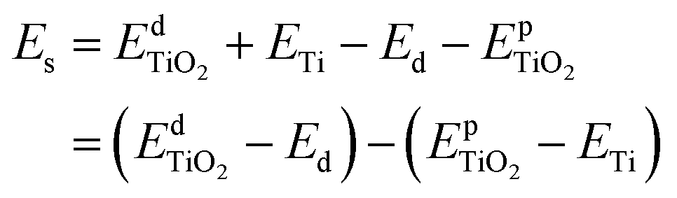
Furthermore, to assess the relative stability of doped TiO2 with different dopants, the substitution energy of the doped systems (Es) is calculated. Considering that each dopant atom replaces a titanium atom in our calculations, as shown in Fig. 1(a), we can use the following equation to get substitution energies:
 | (1) |
 and
and  are the total energies of the doped system and pristine supercell anatase TiO2, respectively; ETi and Ed are energies per atom for metal Ti and dopants, each in the form of its own most stable elementary substance, respectively. The substitution energies of all the doped systems are positive, which indicates that the doped impurities are in metastable states at the local minima, and thus all the doped systems are not as thermodynamically stable as pristine anatase TiO2. This is easy to understand, because all the substitutional doping reactions are not spontaneous processes. But, it is worth noting that the positive substitution energy does not mean that the doped system itself is not thermodynamically stable. To investigate the intrinsic thermodynamic stability of doped TiO2 consisting of one atom doped into the anatase TiO2 host, we further calculated the formation energies of each doped TiO2 system. The formation energies of pristine anatase TiO2 (Epfm) and doped systems (Edfm) can be calculated by eqn (2) and (3), respectively:
 | (2) |
 | (3) |
| Edfm = Es + Epfm | (4) |
From Table 1, we can see that the formation energy values of all the doped systems (Edfm) are negative, which is evident because the substitution energy (Es) values of all the doped systems are much smaller than the absolute value of the formation energy of pristine anatase TiO2 (Epfm), which is calculated as −149.09 eV. The negative formation energy indicates that each doped system itself is thermodynamically stable, consistent with what we mentioned above that most of these elements have been doped in previous experimental works,4,18–74 which proves that all these doped systems are at least thermodynamically stable enough to exist.
In addition, roughly speaking, for metal-doped TiO2 systems, the substitution energy (Es) shows a positive correlation with Nd, which refers to the difference of the number of valence electrons between dopant atom and metal Ti atom, as Fig. 1(b) shows. Especially for the transition metal (from group 4 to group 11)-doped TiO2 systems, Es and Nd are approximately linearly related as eqn (5) shows:
| Es = 1.67Nd + 2.93 | (5) |
3.2. The electron spin state analysis of the dopant atom
Compared with the pristine TiO2 system, each doped system may have extra valence electrons or lack valence electrons, except for the Zr-doped system (because the Nd of Zr equals zero). These relatively extra valence electrons may be in different spin states. For example, when Nd = 3 (such as Mn), the relatively extra 3 valence electrons can be in 2 different spin states: three electrons are all spinning upwards (or downwards), or two electrons are spinning upwards (or downwards) and one electron is spinning downwards (or upwards). If we use Ns to denote the difference between the number of spin up extra valence electrons and the number of spin down extra valence electrons, then these two different situations can be described as Ns = 3 or Ns = 1, and the two different spin states can be denoted as “spin3” and “spin1”, respectively. We call the “spin1” state the low spin state. In other words, the low spin state refers to the state in which Ns is the smallest.The electron spin state is very important in the calculations, as it can severely affect the calculated properties for the system. For example, different electron spin states of a dopant atom can cause different calculated Es values, especially for transition metal dopants, because all the transition metal elements have d-orbitals, and most d-orbital metal-doped TiO2 systems have spin polarization. Thus, it is very necessary to do the electron spin state analysis through which we can find the spin state in which the Es of the system is the lowest, and conversely, by evaluating the value of Es, we can investigate the spin tendency of the electrons of the doped atom.
What needs to be emphasized is that the spin state we discussed in this context refers to the spin state of the relatively extra valence electrons introduced by the dopant. However, since pristine TiO2 is a spin-free system in which the electrons of Ti and O are each paired, the analysis of the spin state of the relatively additional electrons introduced by the impurity atom is equivalent to analyzing the electronic spin state of the entire doped system. Here, taking a transition metal-doped system as an example, let us discuss the relations between the spin state of d-orbital electrons and the Es of the doped system. Fig. 2(a) shows the relations between the Es in different spin states and the Nd, which are similar to what Fig. 1(b) shows, and the difference is that Fig. 2 also shows the influence of spin state on Es. The dopants with Ns ≥ 2 have 2 or 3 different spin structures, which corresponds to the relative extra valence electrons in different spin states, and the different spin states can be characterized by the Ns. Therefore, we name these different spin structures as the low spin structure, middle spin structure and high spin structure, respectively, which correspond to the smallest Ns, the middle Ns and the largest Ns, respectively.
 | ||
| Fig. 2 The electron spin state of transition metal dopant atom and its influence on the substitution energy (Es). (a) The relations between ΔEs and Nd. (b) The relations between Es and Nd. The abscissa Nd is the same as in Fig. 1(b). Es denotes the difference between Es and Els (the substitution energy of doped TiO2 with dopant atom in low spin structure). The low spin structure means that the Ns (the difference between the number of spin up extra valence electrons and the number of spin down extra valence electrons) is the smallest. The term “spin0” refers to Ns = 0, and “spin1” refers to Ns = 1, and so on. For the dopants whose Nd is equal to 2, 3, 4, or 8, their ΔEs is negative, so they tend to have a relatively high spin structure (middle spin structure) in doped TiO2, while for the dopants whose Nd is equal to 5, 6, or 7, their ΔEs is positive, and so they tend to have a low spin structure in doped TiO2. | ||
We can find the lowest Es for each dopant from Fig. 2(a); yet, the spin tendency of each dopant is not obvious in Fig. 2(a). Hence, we plotted Fig. 2(b) by taking the Es of the low spin state as the baseline for each dopant. For the convenience of description, we introduce ΔEs, which is defined in eqn (6), as the ordinate.
| ΔEs = Es − Els | (6) |
The spin tendency can be clearly described by evaluating whether the value of ΔEs is positive or negative. Fig. 2(b) shows some regular patterns for d-orbital metal dopants: for the dopants whose Nd is equal to 2, 3, 4, or 8, their ΔEs is negative, so they tend to have a relatively high spin structure (middle spin structure) in doped TiO2. These dopants are 3-d-orbital metals, Cr, Mn, Fe, and Zn, and 4-d-orbital metals, Mo, Tc, Ru, and Cd. While for the dopants whose Nd is equal to 5, 6, or 7, their ΔEs is positive, so they tend to have a low spin structure in doped TiO2. These dopants are 3-d-orbital metals, Co, Ni, and Cu, and 4-d-orbital metals, Rh, Pd, and Ag.
This is consistent with the results of the crystal field theory. In anatase TiO2, the Ti atom is at the center of an octahedron composed of O atoms, and the doping atom replaces the Ti atom, thereby also filling in the octahedron of O. According to the orbital arrangement rule of the octahedral crystal field (the energy of the three t2g orbitals is lower, and the energy of the two eg orbitals is higher), when Nd is equal to 2, 3, 4 or 8, a relatively high spin arrangement is taken; and when Nd is equal to 5, 6 or 7, a low spin arrangement is taken. In particular, Fig. 2(b) shows that when Nd is equal to 3 or 6, the absolute value of ΔEs is the largest. This corresponds to the states where the three t2g orbitals are half-filled and fully filled, respectively, at which time the energy is at a minimum. Peng et al.78 studied the magnetic properties of 3d transition metal-doped anatase TiO2 by first-principles calculations, and they reported similar results to ours. Our new results show that the 4d transition metal-doped anatase TiO2 possesses similar magnetic properties.
In fact, the electron spin states have already been considered in all the calculations, so all the data (except Fig. 2) are the final results obtained by the calculations performed with the optimum spin state parameters, which makes the doped systems the most thermodynamically stable.
3.3. Electronic structures
The projected density of states (PDOS) of pristine anatase TiO2 is shown in Fig. 3 (labeled with “Ti”). It can be seen that the valence band (VB) and conduction band (CB) are mainly composed of O-2p and Ti-3d-orbitals, respectively. The band structure information can be seen in the ESI.† The band gap of pristine anatase TiO2 is estimated to be 3.59 eV, which is roughly consistent with the experimental value of 3.2 eV.11–14 We also estimated the position of the conduction band minimum (CBM) and valence band maximum (VBM) described by k-point coordinates, and the results are presented in Table S1 (ESI†). It turns out that the band gap of pristine anatase TiO2 presents an indirect nature, which is consistent with previous theoretical109,110 and experimental111,112 results. However, the direct band gap is estimated to be 3.63 eV, which is only 0.4 eV larger than the indirect band gap. Therefore, the band gap of pristine anatase TiO2 can be almost recognized as a direct gap if we judge only from the band structure diagram (Fig. S1, ESI†).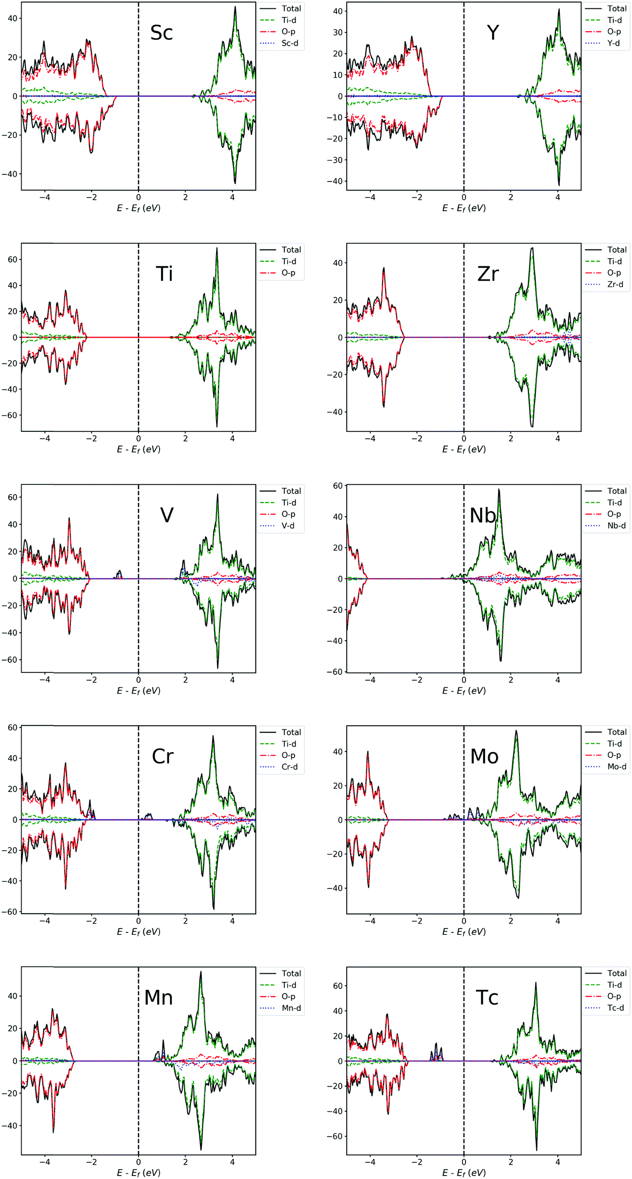 | ||
| Fig. 3 PDOS of Sc, V, Cr, Mn, Y, Zr, Nb, Mo and Tc-doped TiO2 systems and pristine TiO2. The Fermi level is set at zero energy. | ||
For other transition metal-doped TiO2 systems, the number of valence electrons of the dopant is more than that of Ti, and therefore, it is interestingly found that the defect states usually appear in the forbidden gap of the pristine TiO2 to form intermediate bands (IBs). Thus, the intrinsic forbidden gap is divided into two or many sub-gaps by the presence of such IBs. On one hand, the intermediate states can be a stepping stone to help valence electrons get excited into the CB under the illumination of low energy photons, which will promote the efficiency of optical absorption of low energy photons. On the other hand, the IBs would also act as recombination centers, which make electron and hole recombination much easier. The probability of excitation or recombination depends on the energy difference between VB and IBs or CB and IBs. Usually, the deep level defect states easily become recombination centers, and the shallow defect states, in contrast, are beneficial for charge separation. In addition, for most of the transition metal dopants, the defect states of the doped systems are mainly composed of d-orbital states of dopants, except for Cu, Ag, Zn and Cd (Fig. 3 and 4), because these metal dopants possess a fully occupied d-orbital (d10). Especially for the systems doped by Zn and Cd (with a stable electron configuration of d10s2), the defect states with no proportion of d-orbital states from dopants are totally composed of O-2p states of the host (Fig. 4).
 | ||
| Fig. 4 PDOS of Fe, Co, Ni, Cu, Zn, Ru, Rh, Pd, Ag and Cd-doped TiO2 systems. The Fermi level is set at zero energy. | ||
For each Zn, Cd, Ru, Mn, Nb, Mo or Pd-doped TiO2 system, the PDOS from Fig. 3 and 4 shows that all the defect states are nearly at the top of the VB (Zn, Ru and Cd) or the bottom of the CB (Mn, Nb, Mo, Ru and Pd), forming the tail of the VB or CB, which can reduce the band gap. The reduction of band gap can extend its range of optical absorption region to the visible light region, which is beneficial to the improvement of optical absorption efficiency. Thus, doping these transition metals can enhance the photocatalytic efficiency. For Nb-doped TiO2, the Fermi level moves into the CB, which was also reported from previous GGA+U calculations.4,76,79 This means that the electrical conductivity of Nb-doped TiO2 will be very excellent because of the existence of free electrons in the CB, which was confirmed by Yang et al.4 through their combined theoretical and experimental work. Therefore, the photocatalytic efficiency of Nb-doped TiO2 can be promoted vastly by an extended free carrier absorption of visible light and effective charge transfer. In addition, the band structure information (ESI†) reveals that Mo and Cd doping can change the type of band gap, i.e. turning an indirect band gap into a direct one, which is also beneficial for the optical absorption process and will improve the photocatalytic efficiency. These conclusions are in agreement with the previous experimental reports that doping Zn,29,73 Ru,18,22 Cd,26 Mn,25,40 Nb,4,21 and Mo113 can effectively reduce the band gap and thus can obtain visible light responsive TiO2 with finally enhanced photocatalytic efficiency.
For each V, Cr, Fe, Co, Tc, Rh or Ag-doped TiO2 system, it can be seen from Fig. 3 and 4 that parts of the IBs are integrated with the VB or CB and thus reduce the band gap, while the other parts of the IBs are located away from the VBM or CBM, dividing the intrinsic forbidden gap into two parts. The reduction of band gap for all these doped systems has been experimentally reported, such as those for V,64,67 Cr,61 Fe,52 Co,60 Rh57 and Ag.54 However, the reduction of band gap only means that the spectral activity is enhanced, while the eventual photocatalytic efficiency may not be improved because of the existence of recombination centers. For V and Tc-doped TiO2 systems, the energy difference between VBM and IB minimum is much smaller than the energy difference between CBM and IB maximum, so the probability for a hole in the VB to pump up into the IB will be larger than the probability for an electron in the CB to combine with a hole in the IB. This is consistent with previous experimental results64,67 that V doping enhanced the photocatalytic activity under visible light irradiation. While for Cr, Fe, Co and Ni-doped TiO2 systems, the IBs are closer to the CBM than to the VBM, indicating a larger probability for an electron in the CB to combine with a hole in the IB. Especially for Fe and Co-doped systems, the IBs are much closer to the CBM, so the photocatalytic performance of Fe or Co-doped TiO2 will not be very good. This is in agreement with previous experimental results by Li et al.52 that although the absorbing band edge has moved to the visible range after Fe doping into TiO2, the photocatalytic activity is lower than that of the un-doped TiO2. Besides, E. B. Gracien et al.114 experimentally investigated the photocatalytic activity of Mn, Cr and Co-doped TiO2, and they found that the photocatalytic efficiency of Co-doped TiO2 is worse than that of Cr or Mn-doped TiO2 and Mn doping gives the best enhancement, consistent with our theoretical results. As for Cu, Rh and Ag-doped TiO2 systems, their IBs are in the middle of the band gap, which introduces a deep level recombination center. Therefore, despite the reduction of band gap, doping these elements would not improve the photocatalytic performance vastly, which is confirmed by the experimental results by Mahlambi et al.115 They reported that Ag, Co, Ni and Pd-doped TiO2 exhibited photo activity under solar light irradiation, but the photocatalytic activity of the Ag-doped TiO2 is almost as bad as that of the Co or Ni-doped TiO2, and that of the Pd-doped TiO2 is the best.
Peng et al.78 reported their first-principles study on the electronic structures of anatase TiO2 doped with 3d transition metals (V, Cr, Mn, Fe, Co and Ni). There are also IBs appearing in the band gap for most of the systems doped by these elements in their results, which is consistent with ours. However, because they used the LDA type exchange–correlation functional and without the Hubbard U parameter, the position of the IBs is different from ours. In general, because their LDA band gap is too small, many IBs are connected together, like being squeezed, especially for Fe and Co-doped systems, while most IBs are separated in our HSE06 results. Besides, there are more IBs in their results because their doping concentration is 12.5 at%, which is twice that of ours. For example, in their PDOS of the Cr-doped system, the integral area of IBs is quite large, even comparable to the CB or VB, and more importantly, the three t2g states are located away from the VBM and are not clearly separated. By contrast, it can be seen from our Fig. 3 that the integral area of IBs for the Cr-doped system looks relatively small, and it is not comparable to the CB and VB. More importantly, Fig. 3 and 5 show that for Cr-doping, the splitting of two occupied t2g (dxz and dyz) states and one unoccupied t2g (dxy) state has been clearly depicted by the HSE06 method; and compared with their LDA result, the two dxz and dyz states in our HSE06 result have been shifted down to the VBM and are connected to it. The splitting of three t2g states for the Cr-doped TiO2 system has also been reported in the GGA+U study by Yang et al.116 However, in their GGA+U result, the two down shifted dxz and dyz states are still a little bit away from the VBM, revealing that the splitting of dxz (dyz) and dxy states for Cr-doped TiO2 in GGA+U calculations is not as strong as that in HSE06 calculations.
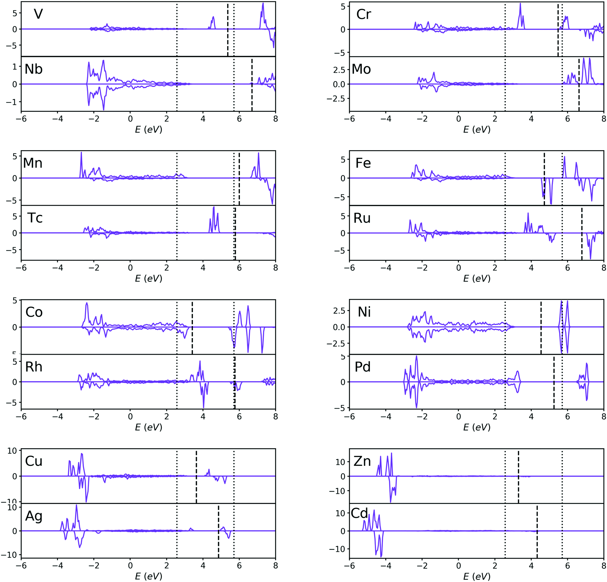 | ||
| Fig. 5 PDOS of the d-orbitals of dopant atoms for V, Cr, Mn, Fe, Co, Ni, Cu, Zn, Nb, Mo, Tc, Ru, Rh, Pd, Ag and Cd-doped TiO2 systems. The dotted lines are the VBM and CBM of pristine TiO2 instead of doped TiO2, and the dashed lines are the Fermi levels of each doped system. The two elements with the same Nd are classified as one pair. For each pair, 4d-orbital transition metals tend to introduce a higher doping level to the system than 3d-orbital transition metals, and the Fermi levels of 4d-orbital metal doped systems are generally higher than those of 3d-orbital metal doped systems (except for Mn–Tc pairs). | ||
Most of the doping levels in the doping system are introduced by valence electrons. Since the valence electrons of all the transition metals are mainly d-orbital electrons, for transition metal-doped systems, the doping levels are mainly determined by the d-orbitals of the dopant atoms (except for Zn and Cd-doped system), as confirmed in Fig. 3 and 4. After a careful analysis of the doping level of transition metals, we found some rules. In order to make these rules clearer, we plot the PDOS of the d-orbitals of dopant atoms separately in Fig. 5. For the sake of comparison, the transition metals were divided into many pairs, such as V–Nb, Cr–Mo, Mn–Tc etc. In each pair, one element comes from a 3d-orbital, another from a 4d-orbital, and both elements have the same Nd. By comparing the two elements in each pair, it is easy to find that 4d-orbital transition metals tend to introduce a higher doping level to the doped systems than 3d-orbital transition metals, just as Fig. 5 shows. Besides, for each pair, the Fermi level of the 4d-orbital metal-doped system is generally higher than that of the 3d-orbital metal-doped system (except for the Mn–Tc pair). These rules indicate that compared with 3d-orbital dopant atoms, the impurity ionization energy of 4d-orbital dopants is generally smaller, meaning that the 4d-orbital electrons are more easily ionized than 3d-orbital electrons in the doped TiO2 systems.
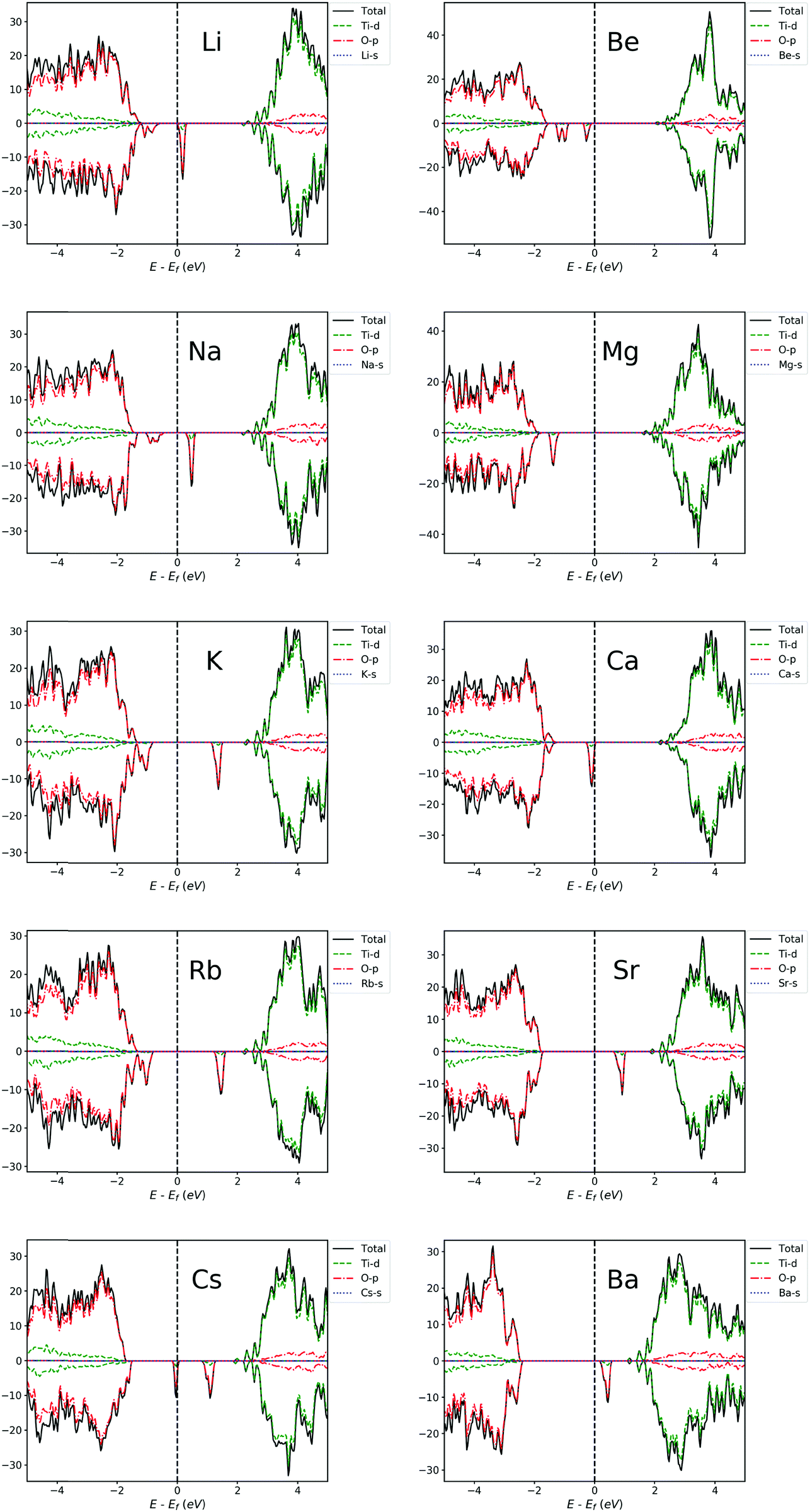 | ||
| Fig. 6 PDOS of Li, Na, K, Rb, Cs, Be, Mg, Ca, Sr and Ba-doped TiO2 systems. The Fermi level is set at zero energy. | ||
For alkali metal-doped TiO2 systems, we can see that the VB moves towards the Fermi level, indicating the increment of concentration of charge carriers and the slight reduction of band gap. It can be seen from Fig. 6 that from Li to Cs, the position of IBs is roughly getting further away from the VBM, making it easier for them to become a recombination center, and thus, the beneficial effects of doping get worse and worse. This is in agreement with previous experimental results by Bessekhouad et al.48 and Yang et al.47 The former investigated the photocatalytic efficiency of Li, Na and K-doped TiO2 and found that the Li-doped system exhibits the best photocatalytic performance among the three. The latter reported that the order of photocatalytic performance for degradation from better to worse is Na > K > Rb. In addition, the lower band gap and photocatalytic activity under sunlight or visible irradiation have been experimentally reported for Li-doped TiO2.46,50
For alkaline earth metal-doped TiO2 systems, the result is similar to alkali metal-doped TiO2 systems, also with the Fermi level shifted towards the VBM and a slightly reduced gap. From Fig. 6, it can be seen that the position of IBs is roughly getting deeper into the gap from Be to Ba, which makes it easier for them to become recombination centers. Hence, roughly speaking, the beneficial effects of Be, Mg and Ca-doping are more obvious. Behnajady et al.42 reported that their experimental results showed a lower band gap energy and a red shift of optical absorption for the Mg-doped anatase TiO2, and Mg-doping ultimately caused the photocatalytic activity of anatase to improve significantly. The enhanced photocatalytic activity has also been experimentally reported for Be-doping44 and Ca-doping.43 In addition, the band structure information (ESI†) indicates that Be, Mg and Ca doping can obtain a direct band gap. Therefore, the beneficial effects of doping these elements will be more evident.
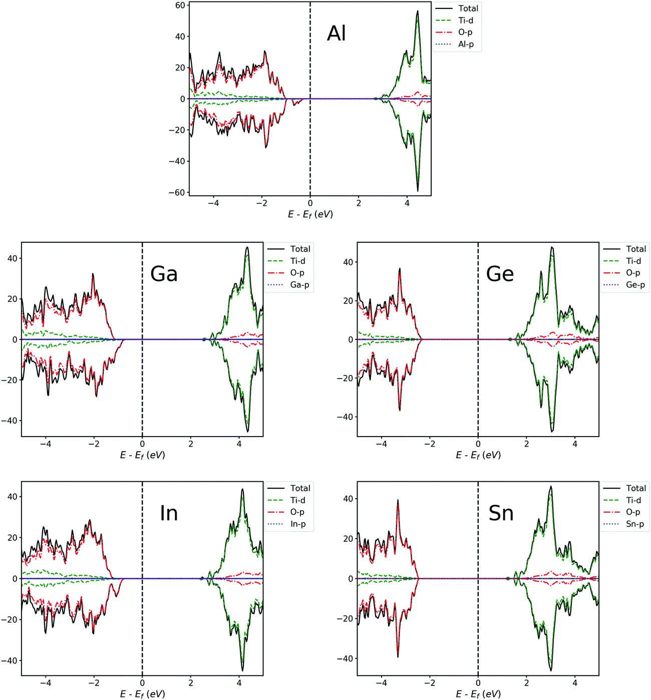 | ||
| Fig. 7 PDOS of Al, Ga, In, Ge and Sn-doped TiO2 systems. The Fermi level is at zero energy. | ||
 | ||
| Fig. 8 PDOS of B, C Si, N, P and S-doped TiO2 systems. The Fermi level is set at zero energy. | ||
4. Conclusions
In summary, anatase TiO2 doped with 40 kinds of elements has been systematically studied by using first-principles calculation at the HSE06 level. The results show that doping with most of these elements can reduce the band gap. However, in some doped systems, the introduced intermediate bands may act as recombination centers and can lower the photocatalytic efficiency. Based on the effect of doping on photocatalytic performance, the doped systems can be divided into three types: (1) Sc, Y, Zn, Ru, Cd, Mn, Nb, Mo, Pd, V, Tc, Li, Na, Be, Mg, Ca, Al, Ga, In, B, N, S and P-doping can reduce the band gap and enhance the photocatalytic efficiency for anatase TiO2. (2) For Cr, Fe, Co, Ni, Cu, Rh, Ag, K, Rb, Cs, Sr, and Ba-doped TiO2 systems, the introduced IBs will make the photocatalytic efficiency lower. (3) For Zr, Ge, Sn, C and Si-doped TiO2 systems, doping has little effect.For transition metal-doped systems, Es and Nd are approximately linearly related. The electron spin state analysis of the dopant atom for transition metal-doped systems shows that Cr, Mn, Fe, Zn, Mo, Tc, Ru and Cd-doped TiO2 tends to have a relatively high spin structure; while Co, Ni, Cu, Rh, Pd and Ag-doped TiO2 tends to have a low spin structure. Besides, 4d-orbital transition metals tend to introduce a higher doping level to doped systems than 3d-orbital transition metals, and the Fermi level of 4d-orbital metal-doped TiO2 is generally higher than that of 3d-orbital metal-doped TiO2, which indicates that the 4d-orbital electrons are more easily ionized than 3d-orbital electrons in doped TiO2 systems.
Conflicts of interest
There are no conflicts to declare.Acknowledgements
This study was financially supported by the National Key R&D Program of China (2016YFB0700600), the National Natural Science Foundation of China (No. 21603007 and 51672012), the Soft Science Research Project of Guangdong Province (No. 2017B030301013), Shenzhen Science and Technology Research Grant (No. JCYJ20150729111733470 and JCYJ20151015162256516), and the New Energy Materials Genome Preparation & Test Key-Laboratory Project of Shenzhen (No. ZDSYS201707281026184).References
- S. U. M. Khan, M. Al-Shahry and W. B. Ingler, Science, 2002, 297, 2243–2245 CrossRef CAS.
- X. Chen, L. Liu, P. Y. Yu and S. S. Mao, Science, 2011, 331, 746–750 CrossRef CAS PubMed.
- S. N. Habisreutinger, L. Schmidt-Mende and J. K. Stolarczyk, Angew. Chem., Int. Ed., 2013, 52, 7372–7408 CrossRef CAS.
- X. Yang, Y. Min, S. Li, D. Wang, Z. Mei, J. Liang and F. Pan, Catal. Sci. Technol., 2018, 8, 1357–1365 RSC.
- S. Ikezawa, H. Homyara, T. Kubota, R. Suzuki, S. Koh, F. Mutuga, T. Yoshioka, A. Nishiwaki, Y. Ninomiya, M. Takahashi, K. Baba, K. Kida, T. Hara and T. Famakinwa, Thin Solid Films, 2001, 386, 173–176 CrossRef CAS.
- A. J. Cowan, J. Tang, W. Leng, J. R. Durrant and D. R. Klug, J. Phys. Chem. C, 2010, 114, 4208–4214 CrossRef CAS.
- A. J. Bard and M. A. Fox, Acc. Chem. Res., 1995, 28, 141–145 CrossRef CAS.
- T. Hasegawa, G. Kinoda, K. Inaba, T. Hitosugi, Y. Hirose, Y. Yamamoto, Y. Furubayashi and T. Shimada, Appl. Phys. Lett., 2005, 86, 252101 CrossRef.
- D. S. Bhachu, S. Sathasivam, G. Sankar, D. O. Scanlon, G. Cibin, C. J. Carmalt, I. P. Parkin, G. W. Watson, S. M. Bawaked, A. Y. Obaid, S. Al-Thabaiti and S. N. Basahel, Adv. Funct. Mater., 2014, 24, 5075–5085 CrossRef CAS.
- X. Yang, M. J. Zhang, Y. Min, M. Xu, Z. Mei, J. Liang, J. Hu, S. Yuan, S. Xiao, Y. Duan, F. Liu, H. Lin, Y. Lin and F. Pan, ACS Appl. Mater. Interfaces, 2017, 9, 29021–29029 CrossRef CAS.
- D. O. Scanlon, C. W. Dunnill, J. Buckeridge, S. A. Shevlin, A. J. Logsdail, S. M. Woodley, C. R. A. Catlow, M. J. Powell, R. G. Palgrave, I. P. Parkin, G. W. Watson, T. W. Keal, P. Sherwood, A. Walsh and A. A. Sokol, Nat. Mater., 2013, 12, 798–801 CrossRef CAS.
- H. X. Zhang, M. Zhao and Q. Jiang, Appl. Phys. Lett., 2013, 103, 023111 CrossRef.
- D. Lee and Y. Kanai, J. Am. Chem. Soc., 2012, 134, 20266–20269 CrossRef CAS.
- D. Tsukamoto, Y. Shiraishi, Y. Sugano, S. Ichikawa, S. Tanaka and T. Hirai, J. Am. Chem. Soc., 2012, 134, 6309–6315 CrossRef CAS.
- U. Diebold, Surf. Sci. Rep., 2003, 48, 53–229 CrossRef CAS.
- T. Xia, N. Li, Y. Zhang, M. B. Kruger, J. Murowchick, A. Selloni and X. Chen, ACS Appl. Mater. Interfaces, 2013, 5, 9883–9890 CrossRef CAS.
- X. Han and G. Shao, J. Phys. Chem. C, 2011, 115, 8274–8282 CrossRef CAS.
- S. Bakardjieva, N. Murafa, V. Houšková, V. Tyrpekl and V. Štengl, Appl. Catal., B, 2009, 89, 613–619 CrossRef.
- P. E. Lippens, A. V. Chadwick, A. Weibel, R. Bouchet and P. Knauth, J. Phys. Chem. C, 2008, 112, 43–47 CrossRef CAS.
- R. Schiller, C. K. Weiss and K. Landfester, Nanotechnology, 2010, 21, 405603 CrossRef.
- E. Uyanga, A. Gibaud, P. Daniel, D. Sangaa, G. Sevjidsuren, P. Altantsog, T. Beuvier, C. H. Lee and A. M. Balagurov, Mater. Res. Bull., 2014, 60, 222–231 CrossRef CAS.
- M. Senthilnanthan, D. P. Ho, S. Vigneswaran, H. H. Ngo and H. K. Shon, Sep. Purif. Technol., 2010, 75, 415–419 CrossRef CAS.
- R. G. Nair, A. Das, S. Paul, B. Rajbongshi and S. K. Samdarshi, J. Alloys Compd., 2017, 695, 3511–3516 CrossRef CAS.
- H. Mansour, R. Bargougui, A. Gadri and S. Ammar, J. Mater. Sci.: Mater. Electron., 2017, 28, 1852–1858 CrossRef CAS.
- C. Y. W. Lin, A. Nakaruk and C. C. Sorrell, Prog. Org. Coat., 2012, 74, 645–647 CrossRef CAS.
- H. Y. Hao, C. X. He, B. Z. Tian and J. L. Zhang, Res. Chem. Intermed., 2009, 35, 705–715 CrossRef CAS.
- X. Chen and C. Burda, J. Am. Chem. Soc., 2008, 130, 5018–5019 CrossRef CAS.
- R. P. Cavalcante, R. F. Dantas, B. Bayarri, O. González, J. Giménez, S. Esplugas and A. Machulek, Catal. Today, 2015, 252, 27–34 CrossRef CAS.
- D. V. Aware and S. S. Jadhav, Appl. Nanosci., 2016, 6, 965–972 CrossRef CAS.
- Y. Lv, L. Yu, H. Huang, H. Liu and Y. Feng, J. Alloys Compd., 2009, 488, 314–319 CrossRef CAS.
- K. M. Reddy, B. Baruwati, M. Jayalakshmi, M. M. Rao and S. V. Manorama, J. Solid State Chem., 2005, 178, 3352–3358 CrossRef CAS.
- R. Asahi, T. Morikawa, T. Ohwaki, K. Aoki and Y. Taga, Science, 2001, 293, 269–271 CrossRef CAS.
- D. N. Bui, S. Z. Kang, X. Li and J. Mu, Catal. Commun., 2011, 13, 14–17 CrossRef CAS.
- A. A. Murashkina, P. D. Murzin, A. V. Rudakova, V. K. Ryabchuk, A. V. Emeline and D. W. Bahnemann, J. Phys. Chem. C, 2015, 119, 24695–24703 CrossRef CAS.
- W. Zhao, W. Wang, X. Feng, L. He, Q. Cao, C. Luan and J. Ma, Ceram. Int., 2017, 43, 8391–8395 CrossRef CAS.
- K. Sato, Y. Yamauchi, X. Jiang, H. Oveisi, A. Beitollahi, Y. Nemoto and N. Fukata, J. Nanosci. Nanotechnol., 2011, 11, 6926–6933 CrossRef PubMed.
- S. Chatterjee and A. Chatterjee, Jpn. J. Appl. Phys., 2008, 47, 1136–1139 CrossRef CAS.
- F. Sayilkan, M. Asiltürk, P. Tatar, N. Kiraz, Ş. Şener, E. Arpaç and H. Sayilkan, Mater. Res. Bull., 2008, 43, 127–134 CrossRef CAS.
- M. Asiltürk, N. Kiraz, F. Sayılkan, E. Arpaç, H. Sayılkan and P. Tatar, J. Hazard. Mater., 2006, 140, 69–74 Search PubMed.
- V. C. Papadimitriou, V. G. Stefanopoulos, M. N. Romanias, P. Papagiannakopoulos, K. Sambani, V. Tudose and G. Kiriakidis, Thin Solid Films, 2011, 520, 1195–1201 CrossRef CAS.
- T. M. Grygar, J. Henych, S. Bakardjieva, V. Štengl and J. Velická, J. Nanomater., 2012, 1–11 Search PubMed.
- M. A. Behnajady, B. Alizade and N. Modirshahla, Photochem. Photobiol., 2011, 87, 1308–1314 CrossRef CAS.
- Y. Castro and A. Durán, J. Sol-Gel Sci. Technol., 2016, 78, 482–491 CrossRef CAS.
- P. Wongwanwattana, P. Krongkitsiri, P. Limsuwan and U. Tipparach, Ceram. Int., 2012, 38, S517–S519 CrossRef CAS.
- H. A. Hamedani, N. K. Allam, M. A. El-Sayed, M. A. Khaleel, H. Garmestani and F. M. Alamgir, Adv. Funct. Mater., 2014, 24, 6783–6796 CrossRef CAS.
- S. Bouattour, W. Kallel, A. M. Botelho Do Rego, L. F. Vieira Ferreira, I. Ferreira Machado and S. Boufi, Appl. Organomet. Chem., 2010, 24, 692–699 CrossRef CAS.
- G. Yang, Z. Yan, T. Xiao and B. Yang, J. Alloys Compd., 2013, 580, 15–22 CrossRef CAS.
- Y. Bessekhouad, D. Robert, J. V. Weber and N. Chaoui, J. Photochem. Photobiol., A, 2004, 167, 49–57 CrossRef CAS.
- T. N. Ravishankar, G. Nagaraju and J. Dupont, Mater. Res. Bull., 2016, 78, 103–111 CrossRef CAS.
- L. Elsellami, H. Lachheb and A. Houas, Mater. Sci. Semicond. Process., 2015, 36, 103–114 CrossRef CAS.
- Z. Mesgari, M. Gharagozlou, A. Khosravi and K. Gharanjig, Spectrochim. Acta, Part A, 2012, 92, 148–153 CrossRef CAS.
- Z. Li, W. Shen, W. He and X. Zu, J. Hazard. Mater., 2008, 155, 590–594 CrossRef CAS.
- C. He, Y. Yu, X. Hu and A. Larbot, Appl. Surf. Sci., 2002, 200, 239–247 CrossRef CAS.
- Y. Li, M. Ma, W. Chen, L. Li and M. Zen, Mater. Chem. Phys., 2011, 129, 501–505 CrossRef CAS.
- E. Grabowskaa, M. Diak, T. Klimczuk, W. Lisowski and A. Zaleska-Medynska, Mol. Catal., 2017, 434, 154–166 CrossRef CAS.
- J. Q. Bai, W. Wen and J. M. Wu, CrystEngComm, 2016, 18, 1847–1853 RSC.
- J. Kuncewicz and B. Ohtani, RSC Adv., 2016, 6, 77201–77211 RSC.
- R. López, R. Gómez and M. E. Llanos, Catal. Today, 2010, 148, 103–108 CrossRef.
- G. Colón, M. Maicu, M. C. Hidalgo and J. A. Navío, Appl. Catal., B, 2006, 67, 41–51 CrossRef.
- C. Te Hsieh, W. S. Fan, W. Y. Chen and J. Y. Lin, Sep. Purif. Technol., 2009, 67, 312–318 CrossRef.
- M. Hamadanian, A. Sadeghi Sarabi, A. Mohammadi Mehra and V. Jabbari, Mater. Sci. Semicond. Process., 2014, 21, 161–166 CrossRef CAS.
- I. Cimieri, H. Poelman, J. Ryckaert and D. Poelman, J. Photochem. Photobiol., A, 2013, 263, 1–7 CrossRef CAS.
- B. Tian, C. Li and J. Zhang, Chem. Eng. J., 2012, 191, 402–409 CrossRef CAS.
- X. Ma, L. Xue, S. Yin, M. Yang and Y. Yan, J. Wuhan Univ. Technol., Mater. Sci. Ed., 2014, 29, 863–868 CrossRef CAS.
- Y. Cai, X. Chen, Y. Wang, M. Qiu and Y. Fan, Microporous Mesoporous Mater., 2015, 201, 202–209 CrossRef CAS.
- A. N. Banerjee, N. Hamnabard and S. W. Joo, Ceram. Int., 2016, 42, 12010–12026 CrossRef CAS.
- J. C. S. Wu and C. H. Chen, J. Photochem. Photobiol., A, 2004, 163, 509–515 CrossRef CAS.
- Alamgir, W. Khan, S. Ahmad, M. Mehedi Hassan and A. H. Naqvi, Opt. Mater., 2014, 38, 278–285 CrossRef CAS.
- S. D. Delekar, H. M. Yadav, S. N. Achary, S. S. Meena and S. H. Pawar, Appl. Surf. Sci., 2012, 263, 536–545 CrossRef CAS.
- D. V. Wellia, Q. C. Xu, M. A. Sk, K. H. Lim, T. M. Lim and T. T. Y. Tan, Appl. Catal., A, 2011, 401, 98–105 CrossRef CAS.
- N. H. Nguyen, H. Y. Wu and H. Bai, Chem. Eng. J., 2015, 269, 60–66 CrossRef CAS.
- W. F. Chen, H. Chen, P. Koshy, A. Nakaruk and C. C. Sorrell, Mater. Chem. Phys., 2018, 205, 334–346 CrossRef CAS.
- P. Benjwal and K. K. Kar, Mater. Chem. Phys., 2015, 160, 279–288 CrossRef CAS.
- B. Zhao, J. Wang, H. Li, H. Wang, X. Jia and P. Su, Phys. Chem. Chem. Phys., 2015, 17, 14836–14842 RSC.
- J.-G. Ma, C.-R. Zhang, J.-J. Gong, Y.-Z. Wu, S.-Z. Kou, H. Yang, Y.-H. Chen, Z.-J. Liu and H.-S. Chen, Materials, 2015, 8, 5508–5525 CrossRef CAS.
- C. Li, Y. F. Zhao, Y. Y. Gong, T. Wang and C. Q. Sun, Phys. Chem. Chem. Phys., 2014, 16, 21446–21451 RSC.
- Q. Hou, C. Zhao and L. Qu, Int. J. Mod. Phys. B, 2016, 31, 1650240 CrossRef.
- H. Peng, J. Li, S. S. Li and J. B. Xia, J. Phys.: Condens. Matter, 2008, 20, 125207 CrossRef.
- J. W. Pan, C. Li, Y. F. Zhao, R. X. Liu, Y. Y. Gong, L. Y. Niu, X. J. Liu and B. Q. Chi, Chem. Phys. Lett., 2015, 628, 43–48 CrossRef CAS.
- K. Yang, Y. Dai and B. Huang, J. Phys. Chem. C, 2010, 114, 19830–19834 CrossRef CAS.
- M. Harb, P. Sautet and P. Raybaud, J. Phys. Chem. C, 2013, 117, 8892–8902 CrossRef CAS.
- Y. X. Han, C. L. Yang, M. S. Wang, X. G. Ma and L. Z. Wang, Sol. Energy Mater. Sol. Cells, 2015, 132, 94–100 CrossRef CAS.
- T. Umebayashi, T. Yamaki, H. Itoh and K. Asai, Appl. Phys. Lett., 2002, 81, 454–456 CrossRef CAS.
- C. Di Valentin and G. Pacchioni, Catal. Today, 2013, 206, 12–18 CrossRef CAS.
- X. D. Liu, E. Y. Jiang, Z. Q. Li and Q. G. Song, Appl. Phys. Lett., 2008, 92, 2006–2009 Search PubMed.
- R. Long, Y. Dai, G. Meng and B. Huang, Phys. Chem. Chem. Phys., 2009, 11, 8165–8172 RSC.
- R. Shirley, M. Kraft and O. R. Inderwildi, Phys. Rev. B: Condens. Matter Mater. Phys., 2010, 81, 075111 CrossRef.
- W. Kohn and L. J. Sham, Phys. Rev., 1965, 140, A1133–A1138 CrossRef.
- G. Kresse and J. Furthmüller, Comput. Mater. Sci., 1996, 6, 15–50 CrossRef CAS.
- G. Kresse and J. Furthmüller, Phys. Rev. B: Condens. Matter Mater. Phys., 1996, 54, 11169–11186 CrossRef CAS.
- J. P. Perdew, K. Burke and M. Ernzerhof, Phys. Rev. Lett., 1996, 77, 3865–3868 CrossRef CAS.
- J. P. Perdew, J. A. Chevary, S. H. Vosko, K. A. Jackson, M. R. Pederson, D. J. Singh and C. Fiolhais, Phys. Rev. B: Condens. Matter Mater. Phys., 1992, 46, 6671–6687 CrossRef CAS.
- A. I. Liechtenstein, V. I. Anisimov and J. Zaanen, Phys. Rev. B: Condens. Matter Mater. Phys., 1995, 52, R5467–R5470 CrossRef CAS.
- J. Heyd and G. E. Scuseria, J. Chem. Phys., 2004, 121, 1187–1192 CrossRef CAS.
- J. Heyd, G. E. Scuseria and M. Ernzerhof, J. Chem. Phys., 2003, 118, 8207–8215 CrossRef CAS.
- J. Heyd, G. E. Scuseria and M. Ernzerhof, J. Chem. Phys., 2006, 124, 219906 CrossRef.
- M. C. Tsai, J. Rick, W. N. Su and B. J. Hwang, Mol. Syst. Des. Eng., 2017, 2, 449–456 RSC.
- M. Matsubara, R. Saniz, B. Partoens and D. Lamoen, Phys. Chem. Chem. Phys., 2017, 19, 1945–1952 RSC.
- M. Harb, P. Sautet and P. Raybaud, J. Phys. Chem. C, 2011, 115, 19394–19404 CrossRef CAS.
- J. Huang, S. Wen, J. Liu and G. He, J. Nat. Gas Chem., 2012, 21, 302–307 CrossRef CAS.
- J. P. Perdew and M. Levy, Phys. Rev. Lett., 1983, 51, 1884–1887 CrossRef CAS.
- W. Jia, Z. Cao, L. Wang, J. Fu, X. Chi, W. Gao and L. W. Wang, Comput. Phys. Commun., 2013, 184, 9–18 CrossRef CAS.
- W. Jia, J. Fu, Z. Cao, L. Wang, X. Chi, W. Gao and L. W. Wang, J. Comput. Phys., 2013, 251, 102–115 CrossRef.
- M. Schlipf and F. Gygi, Comput. Phys. Commun., 2015, 196, 36–44 CrossRef CAS.
- D. R. Hamann, Phys. Rev. B: Condens. Matter Mater. Phys., 2013, 88, 085117 CrossRef.
- H. J. Monkhorst and J. D. Pack, Phys. Rev. B: Condens. Matter Mater. Phys., 1976, 13, 5188–5192 CrossRef.
- M. Horn, C. F. Schwerdtfeger and E. P. Meagher, Z. Kristallogr. - New Cryst. Struct., 1972, 136, 273–281 CrossRef CAS.
- D. T. Cromer and K. Herrington, J. Am. Chem. Soc., 1955, 77, 4708–4709 CrossRef CAS.
- D. Dash, S. Chaudhury and S. K. Tripathy, in Advances in Communication, Devices and Networking, ed. R. Bera, S. K. Sarkar and S. Chakraborty, Springer, Singapore, Singapore, 2018, pp. 57–67 Search PubMed.
- C. Qiang and C. Hong-Hong, Chin. Phys., 2004, 13, 2121–2125 CrossRef.
- Z. Wang, U. Helmersson and P.-O. Käll, Thin Solid Films, 2002, 405, 50–54 CrossRef CAS.
- S. Vyas, R. Tiwary, K. Shubham and P. Chakrabarti, Superlattices Microstruct., 2015, 80, 215–221 CrossRef CAS.
- M. Khan, J. Xu, W. Cao and Z.-K. Liu, J. Nanosci. Nanotechnol., 2014, 14, 6865–6871 CrossRef CAS PubMed.
- E. B. Gracien, J. Shen, X. R. Sun, D. Liu, M. Li, S. D. Yao and J. Sun, Thin Solid Films, 2007, 515, 5287–5297 CrossRef CAS.
- M. M. Mahlambi, A. K. Mishra, S. B. Mishra, R. W. Krause, B. B. Mamba and A. M. Raichur, Ind. Eng. Chem. Res., 2013, 52, 1783–1794 CrossRef CAS.
- K. Yang, Y. Dai and B. Huangl, ChemPhysChem, 2009, 10, 2327–2333 CrossRef CAS PubMed.
Footnotes |
| † Electronic supplementary information (ESI) available. See DOI: 10.1039/c9cp04591k |
| ‡ J. L. and M. W. contributed equally to the present paper. |
| This journal is © the Owner Societies 2020 |