Enhanced VOC of two-dimensional Ruddlesden–Popper perovskite solar cells using binary synergetic organic spacer cations†
Juan
Meng
 ab,
Dandan
Song
ab,
Di
Huang
c,
Yang
Li
ab,
Yaoyao
Li
ab,
Ayman
Maqsood
ab,
Suling
Zhao
ab,
Dandan
Song
ab,
Di
Huang
c,
Yang
Li
ab,
Yaoyao
Li
ab,
Ayman
Maqsood
ab,
Suling
Zhao
 ab,
Bo
Qiao
 ab,
Haina
Zhu
d and
Zheng
Xu
*ab
aKey Laboratory of Luminescence and Optical Information (Beijing Jiaotong University), Ministry of Education, Beijing 100044, China. E-mail: zhengxu@bjtu.edu.cn
bInstitute of Optoelectronics Technology, Beijing Jiaotong University, Beijing 100044, China
cCollege of Traffic Engineering, Hunan University of Technology, Zhuzhou 412007, China
dTianjin Sino-German University of Applied Sciences, Tianjin 300350, China
First published on 17th October 2019
Abstract
Two-dimensional (2D) Ruddlesden–Popper perovskites (RPPs), with the general formula (RNH3)2An−1BnX3n+1, could realize promising device stability as compared with their three-dimensional counterparts. However, the power conversion efficiency (PCE) of perovskite solar cells (PSCs) with 2D RPPs is relatively low, especially the open circuit voltage (VOC) despite the large band gap of 2D RPPs. Herein, to reduce the VOC losses and enhance the PCE, we propose the use of synergetic organic spacer cations with n-butylammonium (BA+, CH3(CH2)3NH3+) as the major spacer cation and octylammonium (OA+, CH3(CH3)7NH3+) as the additive spacer cation. Scanning electron microscopy reveals that 2D RPP films with mixed organic spacer cations (with a 2![[thin space (1/6-em)]](https://www.rsc.org/images/entities/char_2009.gif) :
:![[thin space (1/6-em)]](https://www.rsc.org/images/entities/char_2009.gif) 0.03 molar ratio of BA
0.03 molar ratio of BA![[thin space (1/6-em)]](https://www.rsc.org/images/entities/char_2009.gif) :
:![[thin space (1/6-em)]](https://www.rsc.org/images/entities/char_2009.gif) OA in precursor solution) are more uniform and denser. Furthermore, it is found that the 2D RPPs with OA cations exhibit enhanced charge transport by suppressing low-n phases, which is beneficial for high VOC. With the assistance of the OA spacer cation, the VOC is notably increased from 0.94 V to approximately 1.1 V. PSCs with BA–OA 2D RPP achieve the highest PCE of 11.90%, which is higher than that based on pure BA 2D RPP (10.81%). The unencapsulated devices with BA–OA 2D RPPs retain 63% and 93% of their original PCE after being kept in air with a humidity of 30% ± 5% at a room temperature of 20 °C ± 5 °C for 410 h and in a N2 glove box over 1224 h, respectively. This work provides a simple idea for achieving high quality 2D RPP films, and highlights the importance of organic spacer cations in obtaining highly performed PSCs.
OA in precursor solution) are more uniform and denser. Furthermore, it is found that the 2D RPPs with OA cations exhibit enhanced charge transport by suppressing low-n phases, which is beneficial for high VOC. With the assistance of the OA spacer cation, the VOC is notably increased from 0.94 V to approximately 1.1 V. PSCs with BA–OA 2D RPP achieve the highest PCE of 11.90%, which is higher than that based on pure BA 2D RPP (10.81%). The unencapsulated devices with BA–OA 2D RPPs retain 63% and 93% of their original PCE after being kept in air with a humidity of 30% ± 5% at a room temperature of 20 °C ± 5 °C for 410 h and in a N2 glove box over 1224 h, respectively. This work provides a simple idea for achieving high quality 2D RPP films, and highlights the importance of organic spacer cations in obtaining highly performed PSCs.
Introduction
Organic–inorganic hybrid halide perovskite materials have attracted researchers’ interest owing to their remarkable photo-physical properties such as high absorption coefficient,1 tunable band gaps,2 long carrier diffusion length3 and solution processability.4 The power conversion efficiency (PCE) of perovskite solar cells (PSCs) has received continued increase from 3.8% in 20095 to 24.2% in 2019.6 Although PSCs have achieved efficiencies comparable to those of silicon cells, their stability issues remain to be resolved.Recently, two-dimensional (2D) Ruddlesden–Popper perovskites (RPPs), (RNH3)2An−1MnX3n+1, where RNH3 is the organic spacer cation, A is the cation, M is the metal ion, and X is the halide ion, have been reported to have promising stability.7–9 Their hydrophobic organic spacer cations, which isolate the water and protect the inorganic octahedron, enable better device stability.10 Despite this, the existence of organic spacer cations in 2D RPPs simultaneously induces obstacles for device performance, and the device performance is far from optimization. For example, the reported VOC of the PSCs with a commonly used (BA)2(MA)3Pb4I13 film, generally less than 1.05 V, is obviously lower than the theoretical value (for a forbidden bandgap of ca. 1.63 eV, according to a theoretical VOC of 1.25 V by excluding the Shockley–Queisser limit loss). Correspondingly, the PCE is also low.
To enhance the VOC and the PCE of the PSCs, one essential approach is to improve the film quality and reduce the carrier recombination. It is revealed that the organic spacer cations govern the film quality of the 2D RPPs, while a uniform, dense 2D RPP film is critical for high performance PSCs. Haiying Zheng et al. utilized many kinds of organic spacer cations to construct 2D perovskites, among which (BE)2(FA)8Pb9I28 (BE = C6H5CH2NH3) exhibited a uniform and dense film.11 Yue Hu et al. reported a bifunctional conjugated organic molecule (4-(aminomethyl) benzoic acid hydroiodide) (AB) as an organic spacer cation in organic–inorganic halide perovskite materials,12 the AB cation benefits the growth of perovskite crystals in the mesoporous network. Yani Chen et al. utilized iso-BA ((CH3)2CHCH2NH3+) to replace BA, and they found that (iso-BA)2(MA)3Pb4I13 exhibited a preferential out-of-plane orientation, which led to improved charge mobility along the photocurrent direction in planar PSCs.13 From the studies, it can be seen that the organic spacer cations play important and different roles in the formation of the 2D RPP film and the resultant device performance. Though a series of organic spacer cations are introduced to produce 2D RPPs, as mentioned in the aforementioned studies, synergistically using organic spacer cations is rarely reported. Recently, Huanping Zhou et al. employed a fluorine containing organic molecule 2,2,2-trifluoroethylamine (F3EA) and butylammonium (BA) as mixed spacers; by taking advantage of different organic spacer cations in film formation and carrier kinetics, the PCE of the PSCs is obviously increased.14 Hence, developing synergetic organic spacer cations and simultaneously exploring their different roles in affecting the device performance are crucial to fabricate highly efficient PSCs based on 2D RPPs and screen new organic spacer cations.
Moreover, 2D RPP films also suffer from phase inhomogeneity, which induces carrier recombination and deteriorates the device perforomance.15–17 Typical 2D perovskite films are actually composed of multiple perovskite phases.13,18,19 For example, in a (BA)2(MA)n−1PbnI3n+1 film, it contains phases of n = 2, 3, 4 and ∞ though it is fabricated from the stoichiometric solutions with the expected phase of n = 4. Low-n phases (e.g. n = 1, 2, and 3) can act as hole traps in the perovskite leading to carrier recombination and decreased photovoltaic performance.20–22 Hence, the open circuit voltage (VOC) and the PCE of the PSCs with 2D RPPs are lowered. Thus, to get high VOC, it is also desirable to develop approaches for suppressing the formation of low-n phases in 2D RPP films.23
Herein, we propose the use of binary synergetic organic spacer cations including n-butylammonium (BA+, CH3(CH2)3NH3+) and octylammonium (OA+, CH3(CH3)7NH3+) to decrease the formation of low-n phases and improve the morphology of 2D RPPs. The photoluminescence (PL) and UV-vis absorption spectra indicate that the formation of low-n phases is significantly suppressed by adding OA cations to the perovskite precursor solution. Scanning electron microscopy (SEM) and Kelvin probe force microscopy (KPFM) show that addition of OA can improve the quality of the 2D RPP films. Our device based on a BA–OA mixed 2D RPP film achieves an improved VOC (1.1 V) and an increased PCE (11.9%), which are obviously superior to those of PSCs with a 2D RPP film based on a pure BA cation.
Results and discussion
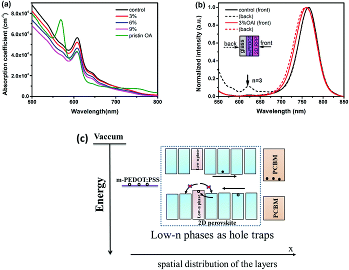
2D RPP films with different molar ratios (3–9%) of OA cations were prepared by a one-step spin coating method. The thickness of the film with pristine a BA spacer cation (abbreviated as control film hereafter), the films with different molar ratios of OA from 3% to 9% (abbreviated as OA-modified (x%) films hereafter) and the film with pristine OA is 303 nm, 320 nm, 335 nm, 442 nm and 357 nm, respectively. Firstly, the normalized UV-vis absorption spectra are recorded and shown in Fig. 1a. The control film exhibits absorption peaks located at 608 nm (2.04 eV), 645 nm (1.93 eV) and 740 nm (1.68 eV), which can be assigned to the excitonic absorption of BA2MAn−1PbnI3n+1 with n = 3, 4, and ∞, respectively.24 Although the 2D RPP film with a pristine OA spacer cation shows quite different absorption features compared with control film, which presents a strong absorption coefficient for small n phases, the introduction of OA does not change the position of the absorption peaks except that the absorption coefficient is decreased with increasing OA content. We calculated the bandgap of the 2D RPP films with different OA contents by a Tauc-plot,25 as shown in Fig. S1 (ESI†). We find that the bandgaps of the control film and the OA-modified (3–9%) films are all 1.63 eV. This indicates that the introduction of OA barely influences the optical bandgap of 2D RPP films, which is reasonable considering the small differences in the composition of these films.To characterize the phase distribution of the deposited films, the photoluminescence (PL) spectra (Fig. 1b) of the control film and the OA-modified (3%) film were recorded under excitation from either the front or back side. For the control film, a dominant emission peak is located at around 765 nm for both excitation sides. An additional peak at around 622 nm (1.99 eV) associated with the phase of n = 324 is found for back excitation. Interestingly, this emission peak was not observed for the OA-modified (3%) film, indicating that OA can decrease the formation of low-n phases (n < 4).22,26 Furthermore, we also observe a redshift of the dominant emission peak in the control film compared with the OA-modified (3%) film, which is likely due to the existence of many larger-n phases or even 3D perovskite.26 It is reported that these low-n phases (e.g. n = 3 phase) can act as hole traps in perovskite films (a schematic illustration indicating low-n phases can act as hole traps22 is shown in Fig. 1c), leading to reduced photovoltaic performances. Therefore, we speculate that the addition of OA cations may be beneficial for reducing carrier recombination.
The time-resolved PL (TRPL) measurement with the excitation from the substrate side was carried out to investigate the carrier recombination kinetics, as shown in Fig. 2. Both PL decay curves can be well fitted by the biexponential function.27,28 The fitting results are listed in Table S1 (ESI†). In comparison with the control film with a carrier lifetime of 16.53 ns, the OA-modified (3%) film shows an obviously longer carrier lifetime of 36.23 ns, indicating that the non-radiation recombination is suppressed in 2D RPP films by introducing OA cations. The reduced carrier recombination may partly result from the decreased low-n phases in the OA-modified (3%) film.
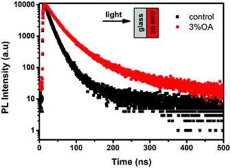 | ||
| Fig. 2 Time-resolved PL (TRPL) spectra of 2D RPP films on glass substrates. The excitation wavelength for TRPL was 485 nm. | ||
Then we conducted X-ray diffraction (XRD) analysis to study the effect of the OA organic spacer cation on the crystallization processes of 2D RPP films, as shown in Fig. 3a. Strong diffraction signals are found at diffraction angles (2θ) of 14.20° and 28.40°, representing the (111) and (222) planes of (BA)2(MA)3Pb4I13.8 There are no additional peaks for all samples, which indicates that the introduction of a small amount of OA, ranging from 3% to 9%, does not affect the crystallinity of 2D RPP films. To investigate the role of OA spacer cation in governing the morphology of the 2D RPP films, top-view scanning electron microscopy (SEM) images were recorded and are shown in Fig. 3b. Compared with the control film, the OA-modified films are more uniform and denser. With the concentration of OA additive increasing from 3% to 9%, the quality of the 2D RPP films are gradually improved.
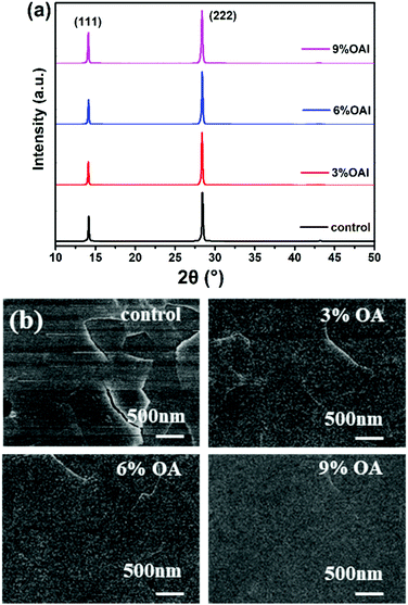 | ||
| Fig. 3 (a) XRD patterns of the 2D RPP films; (b) top-view SEM images of 2D RPP films with different contents of OA cations. | ||
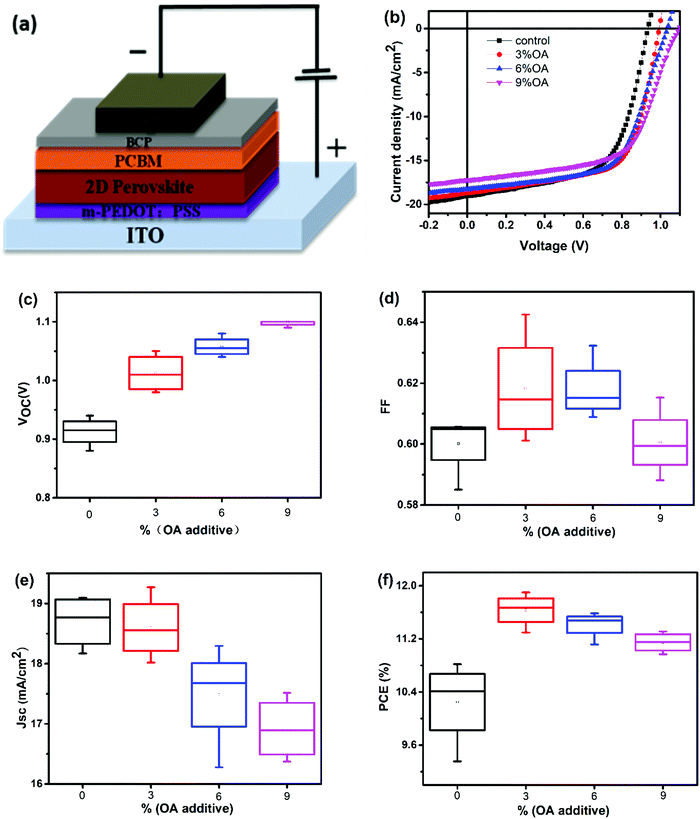
To investigate the effect of OA–BA mixed cations on the device photovoltaic performance, PSCs employing 2D RPPs with different contents of OA spacer cations were fabricated. PSCs have a general device structure of ITO/m-PEDOT:PSS/2D RPP/PCBM/BCP/Ag (as shown in Fig. 4a). The J–V curves and the summarized photovoltaic parameters of the PSCs are shown in Fig. 4b and Table 1. It's clear that the VOC is obviously increased by introducing additional OA, whereas the JSC is lowered, leading to increased PCE from 10.81% for the PSC with a pristine BA spacer cation (abbreviated as control PSC hereafter) to 11.90% for the PSC with 3% OA additive (abbreviated as OA-modified (3%) PSC hereafter).
| OA contents | Best valuesb | Average valuesc | ||||||
|---|---|---|---|---|---|---|---|---|
| J SC (mA cm−2) | V OC (V) | FF (%) | PCE (%) | J SC (mA cm−2) | V OC (V) | FF (%) | PCE (%) | |
| a All of the PSCs were fabricated in the same batch. b The best values were obtained from the PSC with the highest efficiency. c The values were obtained by the average of four identical cells. | ||||||||
| 0 | 19.04 | 0.94 | 0.60 | 10.81 | 18.70 | 0.91 | 0.60 | 10.23 |
| 3% | 18.71 | 0.99 | 0.64 | 11.90 | 18.60 | 1.01 | 0.62 | 11.63 |
| 6% | 18.30 | 1.04 | 0.61 | 11.59 | 17.48 | 1.06 | 0.62 | 11.41 |
| 9% | 17.19 | 1.10 | 0.60 | 11.31 | 16.92 | 1.10 | 0.60 | 11.15 |
The lowered JSC of the OA-modified PSCs can be correlated with the reduced absorption coefficients of the related perovskite films (Fig. 1a). Moreover, the external quantum efficiency (EQE) spectra of PSCs with different molar ratios of OA cations are shown in Fig. S2 (ESI†). The JSC values calculated from the EQE are 18.50, 17.64, 17.49 and 16.99 mA cm−2 for control, OA-modified (3%), OA-modified (6%) and OA-modified (9%) PSCs, respectively, which is consistent with the J–V results. With the contents of OA increasing from 0% to 6%, the EQE at 330–400 nm gradually increases while it decreases at 550–750 nm. As the contents of OA further increase to 9%, the EQE in the entire wavelength range is lowered, which is consistent with its low JSC. For an OA-modified (9%) PSC, the VOC reaches a high value of 1.1 V, which is 160 mV higher than that of the control PSC. However, PSCs with a pure OA organic spacer cation yield quite low efficiency (generally smaller than 1%).
The reproducibility of 2D RPP PSCs with different OA contents was also characterized, as shown in Fig. 4c–f and Table 1. The average VOC of the PSCs upon introducing OA is increased by more than 100 mV and the averaged PCE by more than 10%, demonstrating the great advantage of BA–OA mixed spacer cations in improving the device performance. As the presence of the OA cation has a negligible effect on the bandgap of the 2D RPP films, the obvious increase of VOC of the OA-modified PSCs shall derive other mechanisms.
Since the best photovoltaic efficiency is obtained from the OA-modified (3%) PSC, we then conducted an in-depth analysis on the corresponding optoelectronic behaviour within the control and the OA-modified (3%) PSCs. The device electrical parameters were extracted from the J–V curves and are shown in Fig. 5a and b. Planar structured PSCs can be treated as a single heterojunction diode. The series resistance (Rs) and reverse saturation current (J0) of the cells based on different organic cations can be calculated according to the diode equation4,29,30
 | (1) |
 | (2) |
 | (3) |
 | (4) |
 | ||
| Fig. 5 (a) Plots of dV/dJ versus (JSC + J)−1 and the linear fitting curves, (b) plots of ln(JSC + J) versus (V − Rs·J) and the linear fitting curves, (c) dark J–V characteristics of 2D PSCs. | ||
We further performed kelvin probe force microscopy (KPFM) to investigate the electronic role of the organic cations and the trap states at the 2D RPP surface.31 The topography and the contact potential difference (CPD) images of the control film and the OA-modified (3%) film are shown in Fig. 6. From the topographic images shown in Fig. 6a and b, the root-mean-square roughness (RMS) is estimated to be 13.38 nm and 3.10 nm for the control film and the OA-modified (3%) film, respectively. Hence, the OA-modified (3%) film shows a relatively higher smoothness, which is consistent with the results of SEM. From the CPD images shown in Fig. 6c and d, it's clear that a lower potential appears at the grain boundaries (GBs) for the control film. While adding the OA cation, the potential difference between the grain and the grain boundary is significantly reduced (as also can be seen from the potential profiles shown in Fig. S3, ESI†). The surface morphology and potential might infer that adding OA cation renders perovskite surface smooth and flat in both topological and potential, which might give rise to a lower trap density on the surface.31
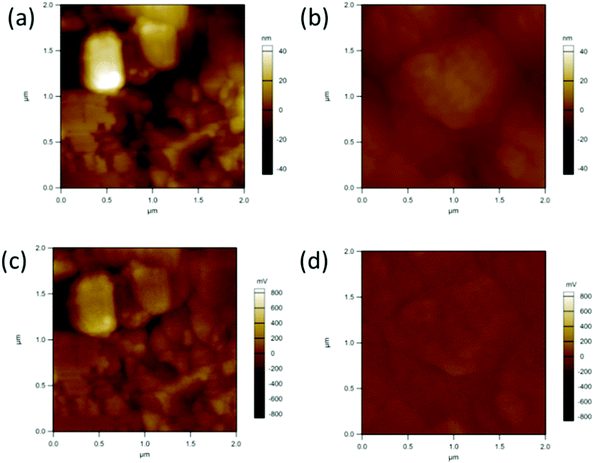 | ||
| Fig. 6 Topography (a and b) and surface potential (c and d) images from films based on the control film and 3% OA additive. | ||
By comparing the effects of OA additive on the crystallinity, morphology and phase distribution features of the 2D RPPs, the reduced recombination by the OA additive can be attributed to the improvement of the morphology and the suppression of the formation of low-n phase (n < 4), which minimizes the carrier recombination inside the perovskite layer. The reduced surface defects, as revealed by the KPFM measurement, may also partially contribute to the reduced carrier recombination and higher VOC in the 2D PSCs. It is worth noting that the suppression of low n phases for the 2D RP perovskite film is specially induced by OA cations, and lowering the content of BA cations in a pure BA based 2D RP perovskite film is not effective (as shown in Fig. S7, ESI†). The role of the OA cations in phase formation of the 2D RP perovskite is investigated by high-resolution transmission electron microscopy (HRTEM) and Fourier transform infrared spectroscopy (FTIR) measurements (as shown in Fig. S5 and S6, ESI†). However, the results show little differences between the control and the OA modified 2D RP perovskite, and the special role of OA in phase formation of the 2D RP perovskite film is still obscure.
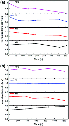
We further determined the average stability of four unencapsulated control PSCs and four OA-modified (3%) PSCs in both an air atmosphere and a N2 glove box. The control PSC retains 67% of its original PCE after being kept in air with a humidity of 30% ± 5% and a temperature of 20 °C ± 5 °C for 410 h (Fig. S4a, ESI†), while the OA-modified (3%) PSC retains 63% of its original PCE after being kept under the same conditions (Fig. 7a). When stored in a N2 glove box, the unencapsulated control PSC retains 94% of its original PCE (Fig. S4b, ESI†), while the unencapsulated OA-modified (3%) PSC retains 93% of its original PCE (Fig. 7b). The slightly inferior stability of PSCs with OA-added perovskite probably originates from the long chain length of OA, which possibly reduces the interaction between the [PbI6]4− layers.18 Both devices showed similar degradation tendency, which indicates that the incorporation of OA does not cause obvious harm to the stability performance of 2D RPPs.
Conclusions
In summary, we propose the use of binary mixed organic spacer cations including BA and OA to enhance the VOC and the PCE of PSCs based on 2D RPPs. We also explore the effect of OA cations on phase formation, morphology and the resultant device performance. We find that OA cations can suppress the formation of low-n phases, improve the morphology, and reduce the surface defects of 2D RPP films. 2D PSCs based on the OA-assisted (BA)2(MA)3Pb4I13 achieved a PCE of 11.90% and a highest VOC of 1.1 V. The device stability is also not hampered by introducing a OA spacer cation. Hence, it is a smart strategy to use BA as the main spacer cation and OA as the additive cation in 2D RPPs, which also highlights the importance and the efficacy of the mixed spacer cation strategy to modify 2D RPP films and the corresponding device performance.Experimental
Materials
CH3NH3I, PbI2, OAI, and BAI were purchased from Xi'an Polymer Light Technology Corp. PC61BM was purchased from Nano-C. PEDOT:PSS was purchased from Clevios AI 4083. The precursor solution of BA2MA3Pb4I13 was composed of PbI2, CH3NH3I and BAI with a molar ratio of 4![[thin space (1/6-em)]](https://www.rsc.org/images/entities/char_2009.gif) :
:![[thin space (1/6-em)]](https://www.rsc.org/images/entities/char_2009.gif) 3
3![[thin space (1/6-em)]](https://www.rsc.org/images/entities/char_2009.gif) :
:![[thin space (1/6-em)]](https://www.rsc.org/images/entities/char_2009.gif) 2 and was stirred in dimethyl formamide (DMF) for one night. The concentration of BA2MA3Pb4I13 precursor solution was 0.3 mol ml−1. The concentration of PC61BM was 20 mg ml−1 in chlorobenzene (CB).
2 and was stirred in dimethyl formamide (DMF) for one night. The concentration of BA2MA3Pb4I13 precursor solution was 0.3 mol ml−1. The concentration of PC61BM was 20 mg ml−1 in chlorobenzene (CB).
Device fabrication
All the perovskite solar cells were fabricated on indium tin oxide (ITO)-coated glass substrates. The ITO substrates with a sheet resistance of 15 Ω □−1 were consecutively cleaned in ultrasonic baths containing glass lotion, de-ionized water, and ethanol. The cleaned ITO glass substrates were dried using nitrogen gas. And then the pre-cleaned ITO substrates were treated with UV-ozone for 15 min for further cleaning the substrates and improving the work function. For devices using modified PEDOT:PSS (m-PEDOT:PSS) as the HTL, m-PEDOT:PSS was prepared by combining 1 ml filtered PEDOT:PSS, 2 ml de-ionized water and 30 mg sodium polystyrenesulfonate (PSS-Na). m-PEDOT:PSS was deposited on ITO substrates at 5000 rounds per minute (rpm) for 20 s. Then the substrates were dried in air at 150 °C for 10 min. After that, the substrates were transferred into a glove box filled with nitrogen. The substrates were pre-heated for 10 minutes at 90 °C.8 And then the BA2MA3Pb4I13 precursor solution was deposited onto m-PEDOT:PSS/ITO substrates at 5000 rpm for 20 s. Substrates coated with perovskite films were thermally annealed at 100 °C for 10 min. Then the PCBM layer was deposited on the BA2MA3Pb4I13 layer at 1000 rpm for 40 s. After that, 8 nm BCP was deposited on top of PCBM layer by electron beam evaporation. Finally, an aluminum cathode layer of about 100 nm was deposited on the BCP layer under 4 × 10⁻⁴ Pa vacuum conditions. The device area is defined by the overlap of the Al and ITO electrodes which is 4 mm2.Device characterization
The thickness of the films was characterized using an Ambios Technology XP-2 stylus profilometer. The current density–voltage (J–V) characteristics of the PSCs were measured using a Keithley 2400 source measurement unit under AM 1.5 G solar irradiation at 100 mW cm−2. Scanning electron microscopy (SEM) measurements were performed using a Hitachi 4800. X-ray diffraction (XRD) patterns were collected with a D/max 2200 V X-ray powder diffractometer with Cu Kα radiation (λ = 1.540 A). The dark J–V devices were measured using a Keithley 2400 source measurement unit under dark conditions. The topography and surface potential images were recorded by MFP-3D Infinity of Asylum Research. The perovskite layer was deposited on a Si substrate. There was no buffer layer between the Si substrate and the perovskite layer. The scanning area and rate were 2.0 μm × 2.0 μm and 1 Hz, respectively. The lift height for KPFM measurements was 5 nm for all samples. The measurement was carried out under dark conditions. All characterizations were carried out under constant exposure to ambient atmosphere and without any encapsulation of the perovskite cells.Conflicts of interest
There are no conflicts to declare.Acknowledgements
This work was supported by the Fundamental Research Funds for the Central Universities 2018YJS172, the National Natural Science Foundation of China under Grant No. 61575019 and 61775013; the Fundamental Research Funds for the Central Universities with the Grant No. 2017RC034, 2017RC015 and 2017JBZ105.Notes and references
- C. C. Stoumpos, C. D. Malliakas and M. G. Kanatzidis, Inorg. Chem., 2013, 52, 9019–9038 CrossRef CAS.
- S. D. Stranks, G. E. Eperon, G. Grancini, C. Menelaou, M. J. Alcocer, T. Leijtens, L. M. Herz, A. Petrozza and H. J. Snaith, Science, 2013, 342, 341–344 CrossRef CAS.
- F. Hao, C. C. Stoumpos, R. P. Chang and M. G. Kanatzidis, J. Am. Chem. Soc., 2014, 136, 8094–8099 CrossRef CAS.
- Y. Li, Z. Xu, S. Zhao, B. Qiao, D. Huang, L. Zhao, J. Zhao, P. Wang, Y. Zhu, X. Li, X. Liu and X. Xu, Small, 2016, 12, 4902–4908 CrossRef CAS.
- A. Kojima, K. Teshima, Y. Shirai and T. Miyasaka, J. Am. Chem. Soc., 2009, 131, 6050–6051 CrossRef CAS.
- https://www.nrel.gov/pv/ .
- I. C. Smith, E. T. Hoke, D. Solis-Ibarra, M. D. McGehee and H. I. Karunadasa, Angew. Chem., Int. Ed., 2014, 53, 11232–11235 CrossRef CAS.
- H. Tsai, W. Nie, J. C. Blancon, C. C. Stoumpos, R. Asadpour, B. Harutyunyan, A. J. Neukirch, R. Verduzco, J. J. Crochet, S. Tretiak, L. Pedesseau, J. Even, M. A. Alam, G. Gupta, J. Lou, P. M. Ajayan, M. J. Bedzyk and M. G. Kanatzidis, Nature, 2016, 536, 312–316 CrossRef CAS PubMed.
- S. Chen and G. Shi, Adv. Mater., 2017, 29, 1605448 CrossRef.
- J. Qing, X.-K. Liu, M. Li, F. Liu, Z. Yuan, E. Tiukalova, Z. Yan, M. Duchamp, S. Chen, Y. Wang, S. Bai, J.-M. Liu, H. J. Snaith, C.-S. Lee, T. C. Sum and F. Gao, Adv. Energy Mater., 2018, 8, 1800185 CrossRef.
- H. Zheng, G. Liu, L. Zhu, J. Ye, X. Zhang, A. Alsaedi, T. Hayat, X. Pan and S. Dai, Adv. Energy Mater., 2018, 8, 1800051 CrossRef.
- Y. Hu, Z. Zhang, A. Mei, Y. Jiang, X. Hou, Q. Wang, K. Du, Y. Rong, Y. Zhou, G. Xu and H. Han, Adv. Mater., 2018, 30, 1705786 CrossRef.
- Y. Chen, Y. Sun, J. Peng, W. Zhang, X. Su, K. Zheng, T. Pullerits and Z. Liang, Adv. Energy Mater., 2017, 7, 1700162 CrossRef.
- S. Tan, N. Zhou, Y. Chen, L. Li, G. Liu, P. Liu, C. Zhu, J. Lu, W. Sun, Q. Chen and H. Zhou, Adv. Energy Mater., 2018, 1803024, DOI:10.1002/aenm.201803024.
- C. M. M. Soe, W. Nie, C. C. Stoumpos, H. Tsai, J.-C. Blancon, F. Liu, J. Even, T. J. Marks, A. D. Mohite and M. G. Kanatzidis, Adv. Energy Mater., 2018, 8, 1700979 CrossRef.
- L. Etgar, Energy Environ. Sci., 2018, 11, 234–242 RSC.
- J. Yan, W. Qiu, G. Wu, P. Heremans and H. Chen, J. Mater. Chem. A, 2018, 6, 11063–11077 RSC.
- C. Ma, D. Shen, T. W. Ng, M. F. Lo and C. S. Lee, Adv. Mater., 2018, 30, e1800710 CrossRef.
- M. E. Kamminga, H.-H. Fang, M. R. Filip, F. Giustino, J. Baas, G. R. Blake, M. A. Loi and T. T. M. Palstra, Chem. Mater., 2016, 28, 4554–4562 CrossRef CAS.
- X. Zhang, X. Ren, B. Liu, R. Munir, X. Zhu, D. Yang, J. Li, Y. Liu, D.-M. Smilgies, R. Li, Z. Yang, T. Niu, X. Wang, A. Amassian, K. Zhao and S. Liu, Energy Environ. Sci., 2017, 10, 2095–2102 RSC.
- X. Meng, X. Cui, M. Rager, S. Zhang, Z. Wang, J. Yu, Y. W. Harn, Z. Kang, B. K. Wagner, Y. Liu, C. Yu, J. Qiu and Z. Lin, Nano Energy, 2018, 52, 123–133 CrossRef CAS.
- C. Ma, M.-F. Lo and C.-S. Lee, J. Mater. Chem. A, 2018, 6, 18871–18876 RSC.
- A. H. Proppe, R. Quintero-Bermudez, H. Tan, O. Voznyy, S. O. Kelley and E. H. Sargent, J. Am. Chem. Soc., 2018, 140, 2890–2896 CrossRef CAS.
- J. Liu, J. Leng, K. Wu, J. Zhang and S. Jin, J. Am. Chem. Soc., 2017, 139, 1432–1435 CrossRef CAS.
- I. Zimmermann, S. Aghazada and M. K. Nazeeruddin, Angew. Chem., Int. Ed., 2019, 58, 1072–1076 CrossRef CAS.
- X. Zhang, R. Munir, Z. Xu, Y. Liu, H. Tsai, W. Nie, J. Li, T. Niu, D. M. Smilgies, M. G. Kanatzidis, A. D. Mohite, K. Zhao, A. Amassian and S. F. Liu, Adv. Mater., 2018, 30, e1707166 CrossRef.
- Z. Wang, D. P. McMeekin, N. Sakai, S. van Reenen, K. Wojciechowski, J. B. Patel, M. B. Johnston and H. J. Snaith, Adv. Mater., 2017, 29, 1604186 CrossRef.
- A. Jain, H. Tan, O. Voznyy, X. Lan, F. P. García de Arquer, J. Z. Fan, R. Quintero-Bermudez, M. Yuan, B. Zhang, Y. Zhao, F. Fan, P. Li, L. N. Quan, Y. Zhao, Z.-H. Lu, Z. Yang, S. Hoogland and E. H. Sargent, Science, 2017, 355, 722–726 CrossRef.
- J. Shi, J. Dong, S. Lv, Y. Xu, L. Zhu, J. Xiao, X. Xu, H. Wu, D. Li, Y. Luo and Q. Meng, Appl. Phys. Lett., 2014, 104, 063901 CrossRef.
- J. You, Y. Yang, Z. Hong, T.-B. Song, L. Meng, Y. Liu, C. Jiang, H. Zhou, W.-H. Chang, G. Li and Y. Yang, Appl. Phys. Lett., 2014, 105, 183902 CrossRef.
- D. Song, D. Wei, P. Cui, M. Li, Z. Duan, T. Wang, J. Ji, Y. Li, J. M. Mbengue, Y. Li, Y. He, M. Trevor and N.-G. Park, J. Mater. Chem. A, 2016, 4, 6091–6097 RSC.
Footnote |
| † Electronic supplementary information (ESI) available. See DOI: 10.1039/c9cp04018h |
| This journal is © the Owner Societies 2020 |

