Dodecagonal quasicrystal silicene: preparation, mechanical property, and friction behaviour
Chen
Qian
 and
Jiugen
Wang
*
Department of mechanical engineering, Zhejiang University, 866 Yuhangtang Rd, Hangzhou 310058, P. R. China. E-mail: me_jg@zju.edu.cn
First published on 18th November 2019
Abstract
In this study, we obtained dodecagonal monolayer silicene with three-fold and four-fold coordination by melt quenching via molecular dynamics (MD) simulations. Stretching simulation of the pre-strained dodecagonal silicene showed lower critical stress than the honeycomb silicene and resulted in an increase in six-fold rings during the plastic deformation since the four-coordinated atom sites are less mechanically favoured than the three-coordinated sites. The friction behaviours with an AFM tip sliding on the dodecagonal and honeycomb surfaces under different loads and tip sizes were simulated and compared. For all the investigated cases, the dodecagonal surface always showed a lower mean friction force than the honeycomb surface. The lower friction of the quasicrystal was observed, and the mechanism was illuminated successfully for the first time by MD simulations. The reduced friction of dodecagonal silicene can be explained by the morphology of the one-dimensional potential energy surface (PES). The 1D PES of dodecagonal silicene has longer potential corrugation lengths than honeycomb silicene, which induce mild motion of the tip in the stick process and lower friction force. Considering the close density of the employed dodecagonal and honeycomb structure, the longer potential corrugation length is a consequence of the quasiperiodic morphology rather than the interspace between atoms. Besides, with a larger tip size, the 1D PES on the dodecagonal surface has a flatter area, which contributes further to the reduced friction force on the dodecagonal surface.
1. Introduction
Quasicrystals are long-range ordered materials that lack translational symmetry and show 5-fold, 8-fold, 10-fold and 12-fold symmetry order, which are forbidden due to the crystallographic restriction theorem. The discovery of quasicrystals by Daniel Shechtman has attracted considerable attention and expanded the scope of crystallography.1 The family of quasicrystals consists of three-dimensional icosahedral phases (Mackay,2 Bergman3 and Tsai4 type), two-dimensional octagonal,5 decagonal,6 dodecagonal7 QCs and the one-dimensional type with a Fibonacci sequence.8 Most of them are observed in multicomponent metallic systems, while a few types of organic quasicrystals have been discovered in recent years.9–11 One-component icosahedral quasicrystals have been assembled by molecular dynamics simulation via an isotropic pair potential.12 The only reported single-component quasiperiodic phase in experiment is the Si decagonal phase through evaporation and annealing in helium.13 Furthermore, a dodecagonal silicon bilayer has been obtained by quenching from 1800 K under 3.35 GPa between two smooth Lennard-Jones potential walls with molecular dynamics simulation.14 Quasicrystal materials are featured with the peculiarly of very lower friction even compared with periodic approximants, which cannot be explained solely by their high hardness and Young's modulus and demonstrates the complexity of the mechanism.15–20 High frictional anisotropy in periodic and aperiodic direction was observed for Al–Co–Ni quasicrystals with friction along the 2-fold axis merely 1/8 of that along the 10-fold axis.21 The Langevin model was adopted by Filippov to reproduce the friction anisotropy and the anisotropy was attributed to the different substrate corrugation length scales in the sliding directions rather than quasiperiodicity itself.22 Whereas, the parameters used in Filippov's model were fitted from the friction experiment result. Besides, further research showed that the result of the Langevin model is quite sensitive to the parameters, and Filippov's parameters were not in accordance with the STM image of the substrate.23Most bulk quasicrystals exhibit desirable properties including high brittleness, low friction, low surface energy, high hardness, wear resistance, anti-corrosion, high thermal resistance, high resistance, excellent dispersion strengthening property and hydrogen storage.15–20,24 Furthermore, the micro-pillar experiment on an Al–Pd–Mn icosahedral quasicrystal and Al–Co–Ni exhibited the highest specific strength among reported materials to our knowledge with excellent ductility.25,26 Moreover, the properties of quasicrystals in the nanoscale remain to be explored.
With the prosperity of 2D materials, silicene has garnered widespread interest due to its compatibility with bulk silicon in micro-electro mechanical systems (MEMS) and the semiconductor industry. Silicene nanosheets with different superstructures have been epitaxially deposited on the surfaces of Ag(111),27 Ag(110),28 Ir(111),29 ZrB2(0001),30 ZrC(111)31 and MoS2.32 The scalable fabrication of high-quality silicene has been successfully achieved with mild oxidation and exfoliation of Ca2Si.33 Free-standing monolayer silicene has a low buckled honeycomb structure with a lattice constant of 3.84 Å and buckling length of 0.40 Å due to pseudo-Jahn–Teller distortion (PJT).34 Its band structure shows massless Dirac fermion-like charge carrier, while its π and π* bands cross linearly through the Fermi level.35 Also, its bandgap is tunable with electrical field,36 making it a potential candidate for electrical field transistors.37 First principle calculation predicted that silicene doped by transition metal elements (Cu, Ag, Au, Pt, and Ir) will induce a sizeable direct bandgap at specific coverage and enables a p–i–n junction with three types of doping at different regions.38 The oxidation of the silicene superstructure surface on the Ag(111) substrate can open a tunable bandgap ranging from 0.11 to 0.30 eV.39 When the stacking mode of bilayer silicene was investigated, the indirect bandgaps of 0.29 eV and 1.16 eV were observed for the AA′ and slide-2AA morphologies, respectively.40,41 The in-plane stiffness of monolayer silicene obtained by DFTB is 62.7 N m−1 in the zigzag direction and 63.4 N m−1 in the armchair direction, which are merely 10% of that of graphene.42 Furthermore, recent studies showed its potential application for the absorption of toxic gases (NO2 and SO2),43 hydrogen storage44 and as an anode material for lithium-ion batteries.45
In this context, we employed massive parallel molecular dynamics simulation to obtain monolayer dodecagonal silicene with procedures analogous to that used for bilayer silicon quasicrystals. The obtained monolayer dodecagonal conformation was mechanically unstable at room temperature, and thus further steps were adopted to stabilise the dodecagonal structure at 10 K. Simulation of the quasicrystal silicene in tension was performed to study its mechanical property and fracture dynamics. Considering the low friction coefficient property of bulk quasicrystals, friction tests of the quasicrystal silicene were performed in contact mode using an atomic force microscope (AFM).
2. Computational detail
Classical molecular dynamics simulations were performed using Large-scale Atomic/Molecular Massively Parallel Simulator (LAMMPS) to simulate the synthesis, tensile test, and friction behaviour of dodecagonal silicene.46 The open visualization tool (OVITO) was used for data post-processing and result visualization.47 The interatomic potential between silicon atoms was described with the 3-body Stillinger–Weber potential,48 | (1) |
 | (2) |
 | (3) |
Silicon was firstly melted into a liquid and confined between two Lennard-Jones 9-3 potential walls,
 | (4) |
Tensile simulation of dodecagonal silicene was performed under periodic boundary condition with ample vacuum space in the vertical direction to eliminate periodic image. The quasicrystal silicene size used for tension was 110.8 Å × 196.9 Å in the x- and y-direction, respectively, while a quasicrystal of a specific size could not be constructed with simple replication of a unit cell, and the size of prepared dodecagonal silicene is only relevant to the initial state of liquid silicon and quenching process. The Velocity-Verlet integrator was used to update the velocity and position every 1 fs. Dodecagonal silicene was stretched with a strain rate of 108 s−1 in the y-direction and the length of the simulation box in the x-direction was kept constant. Therefore, silicene was subject to a biaxial stress state during the tensile process. The Nose–Hoover thermostat was coupled to control the temperature at 10 K with a temperature damping parameter of 100 fs. To obtain the stress–strain relationship, the virial tensor52 was calculated as follows:
 | (5) |
 | (6) |
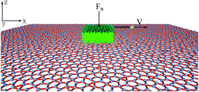
To probe the friction on the incommensurate surface, the simulation was performed as a diamond tip sliding across the dodecagonal silicene, which is illustrated in Fig. 1. During the stick-slip process, the tip can have a high instantaneous speed and excessive oscillation, which interfere with observation. The kinetic energy is typically dissipated through the materials in contact by a thermostat. However, for the hemispherical tip and rigid silicene, the limited contact area will aggravate the oscillation. Therefore, a diamond block was adopted to increase the contact area and eliminate the excessive oscillation. The tip movement perpendicular to the sliding direction was confined to the original position. The size of the tip was 20 Å × 20 Å × 10 Å, while the topmost 3 Å slab of the silicon atoms was rigid. The load was imposed directly on the rigid part of the tip. In the lateral direction, the rigid layer was coupled to a virtual atom with the spring, while the virtual atom moved with constant velocity and pulled the tip forward during the sliding process. The stiffness of the spring k = 10 N m−1 was used to mimic the compliance of the AFM system cantilever, which has been employed in previous studies,53 and that k is larger than the effective stiffness of the contact. Unlike graphene, which is chemically inert, silicene (especially dodecagonal silicene) presents higher chemical activities. Consequently, the friction with the diamond tip would easily lead to the damage of the silicene. Thus, to preserve the structures, the silicene was set as rigid during the friction process. In previous literature, rigid phosphorene54 and rigid crystalline surfaces55,56 were successfully used to explore the effects of lattice commensurability on friction with MD simulations. A small time step of 1 fs was adopted to capture the motion of the diamond tip. The Lennard-Jones potential  was used for interaction between silicon and carbon atoms, where ε and σ were 0.092 eV and 3.0 Å with a cutoff radius equal to 10 Å, respectively. These LJ parameters were successfully used to describe the van der Waals force between graphene and a silicon tip.57 The covalent bond of C–C in the diamond tip was described with widely used Tersoff potential. The system was initially relaxed for 100 ps with a load of 40 nN. Then the virtual atom was moved with a constant velocity of v = 2 nm ns−1 for 3 ns (6 nm in the sliding direction). The force coupled to the virtual atom was recorded as the friction force of the diamond tip. The temperature was 10 K to exclude thermal fluctuation and controlled with the Nose–Hoover thermostat under an NVT ensemble. Furthermore, friction on the zigzag direction of monolayer silicene was simulated under the same condition for comparison.
3. Result and discussion
3.1 Evolution and structure of dodecagonal silicene
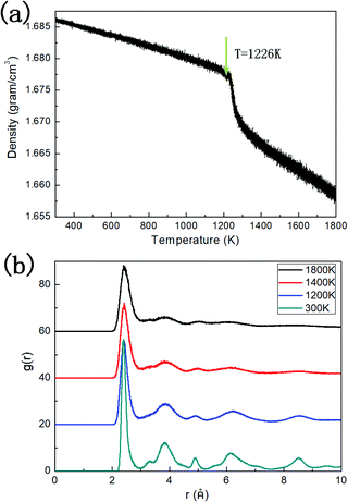
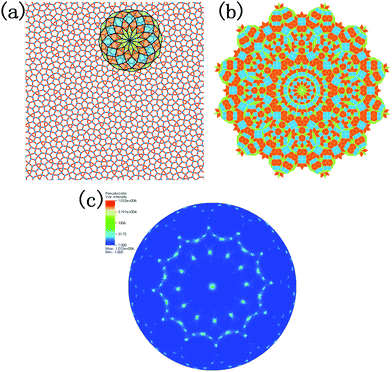
The density of the system evolving with temperature during the quenching process is illustrated in Fig. 2a. Two linear regions between density and temperature can be distinguished, where one corresponds to the liquid phase at higher temperature, and the other corresponds to the dodecagonal solid structure. The break between these two regions can be explained by the phase transition from the liquid phase to the dodecagonal structure. The phase transition temperature derived from Fig. 2a is around 1226 K, which is much lower than that of the dodecagonal bilayer silicon with Tm = 1646 ± 10 K.14 The density of the dodecagonal silicene is 1.69 g cm−3, which is slightly smaller than that of low buckled silicene,58i.e., 1.74 g cm−3 and equal to that of the planar honeycomb structure.49 The reduced density for dodecagonal silicene is a result of the suppressed buckling length in the out-of-plane direction and the smaller angle between the bonds and the atomic plan.Fig. 2b shows the radial distribution function (RDF) of the system at different temperatures. The smooth attenuation of RDF after the first peak at 1800 K shows a typical feature for the liquid phase. As the temperature approaches the value of 1200 K, the third, fourth and fifth peaks emerge, indicating a phase transition from liquid to a solid structure. Besides, the value of 1200 K is close to the phase transition temperature of 1226 K derived from Fig. 2a. At the temperature of 300 K, more distinct RDF peaks can be found. The local atomic structure of dodecagonal silicene at 300 K is illustrated in Fig. 3a. For the coordination number (CN) of the dodecagonal structure at 300 K, 54.1% is equal to 3 and 45.9% is equal to 4, indicating an sp2 and sp3 hybridization mode, respectively. The cutoff radius used for CN is 3 Å, which is the first minimum of the RDF. In Fig. 3a, a dodecagonal cluster is mapped into a 12-fold tiling with some distortion since the SW potential favors the tetrahedral angles of bulk silicon. For comparison, a perfect dodecagonal tiling59 is illustrated in Fig. 3b. The selected area electron diffraction (SAED)60 was simulated for the structure at 300 K, as shown in Fig. 3c. The diffraction pattern in Fig. 3c shows a symmetry of 12-fold, indicating the dodecagonal conformation. To quantify the disorder of the dodecagonal silicene, we performed additional SAED calculations for a perfect dodecagonal quasi-lattice and the low bucked honeycomb silicene. The perfect dodecagonal quasi-lattice was obtained by the projection method.61 The percentages of the frames in the SAED patterns with an intensity higher than 50 (10) are 1.13% (6.03%), 1.10% (3.64%) and 0.59% (1.72%) for the dodecagonal silicene, the perfect dodecagonal quasi-lattice and the low buckled honeycomb silicene, respectively. The degree of localization in the k-space for the dodecagonal silicene is slightly lower than that of the perfect dodecagonal quasi-lattice and lower than that of the low buckled honeycomb silicene. Note that the preparation of the dodecagonal silicene still conforms to the Mermin–Wagner theorem due to the presence of the potential walls in the third direction.
3.2 Mechanical property and fracture dynamics
Dodecagonal silicene under tension was simulated at 10 K to study its mechanical property and fracture dynamics. Fig. 4a shows the stress versus strain curve and coordination number evolution behaviour of the pre-strained dodecagonal silicene during the stretching process. The atomic Von Mises stress distributions at different strains of 0, 0.05 and 0.1 are presented in Fig. 4b–d, respectively. The critical strength of dodecagonal silicene is 12.86 GPa, which is much lower than that of the low buckled honeycomb structure (σc = 27.80 GPa and 25.24 GPa in the armchair and zigzag directions, respectively). As shown in Fig. 4b, the silicon atoms with a coordination number of 4 suffer from higher local Von Mises stress than that with a coordination number equal to 3. This phenomenon indicates that atoms with a coordination number of 4 are less mechanically favoured in dodecagonal silicene. Furthermore, the atoms with a coordination number of 4 tended to break one covalent bond during the tensile process, which resulted in an increase in the amount of atoms with a coordination number equal to 3 before the final fracture in Fig. 4a. The increase in atoms with a coordination number of 3 is in accordance with more honeycomb structures within the high stressed area, as shown in Fig. 4b–d.3.3 Friction behaviour of the incommensurable structure
Low friction and adhesion of quasicrystals have been reported right after their discovery, but their origin is still controversy regardless of the countless efforts. Here, we present the result of the molecular dynamics simulation which shows the lower friction of the dodecagonal silicene than the honeycomb silicene and explains the mechanism of the potential energy barrier.Fig. 5 shows the friction force versus sliding distance relationship for the low buckled honeycomb and dodecagonal silicene. The typical stick-slip pattern of the atomic force microscope is observed. For the honeycomb structure, the curve of the frictional force indicates some multiple-slip mechanism with a sliding length of around either 3.9 Å or 7.7 Å, which is almost equal to the lattice constant of 3.84 Å or twice that. In contrast, the stick-slip friction for dodecagonal silicene is aperiodic with a varying peak force in the studied sliding length scale as a result of the quasiperiodic morphology. Both the mean friction force and peak force of the honeycomb structure are significantly larger than that of the dodecagonal silicene. However, it is not convincing to conclude that the dodecagonal structure will induce a lower friction force since the low buckled honeycomb structure has a larger buckling length. Further simulations were performed with all the silicon atoms in the same atomic plan for both the honeycomb and dodecagonal silicene.
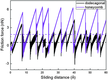 | ||
| Fig. 5 Stick-slip friction pattern of low buckled honeycomb and dodecagonal silicene with a tip side length of 20 Å under a load of 40 nN. | ||
To study the load dependency of friction force, loads of 20 nN, 40 nN, 60 nN and 80 nN were applied to the diamond tip. Fig. 6a shows the mean friction as a function of the load on the planar honeycomb and dodecagonal silicene. The mean friction forces of the planar structures (0.68 nN for the dodecagonal silicene and 1.13 nN for the honeycomb silicene) under the load of 40 nN were lower than that for their buckled counterparts (0.90 nN for the dodecagonal silicene and 2.95 nN for the honeycomb silicene), which was expected due to the larger atomic asperities of the buckled structures. For both planar structures, the mean force increased monotonically with load, and the difference between the honeycomb and dodecagonal structures widened for a larger load. For each load investigated, dodecagonal silicene always showed a lower mean friction force than the honeycomb silicene. It seems that the lower friction force of dodecagonal silicene is an intrinsic property instead of a result of specific loads.
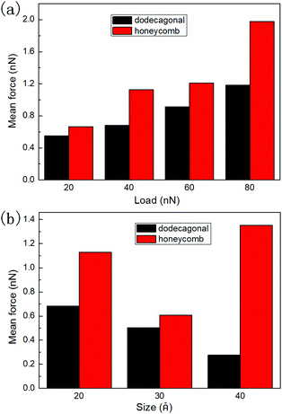 | ||
| Fig. 6 Mean friction force of planar honeycomb and dodecagonal silicene: (a) under loads of 20 nN, 40 nN, 60 nN and 80 nN and (b) with tip side lengths of 20 Å, 30 Å and 40 Å. | ||
To exclude the effect of tip size, we simulated the sliding process with the tip of side lengths equal to 20 Å, 30 Å and 40 Å under a load of 40 nN. The height of the tip for both cases was 10 Å. The mean friction with different tip sizes is illustrated in Fig. 6b. For each tip size, the mean friction on the planar dodecagonal silicene was always lower than the planar honeycomb silicene. The mean friction of the dodecagonal structure decreased monotonically with an increase in the size of the tip. Differently from the monotonic decreasing tendency of dodecagonal silicene, the mean force of the honeycomb structure firstly decreased as the tip size changed from 20 Å to 30 Å and then increased as tip size increased to 40 Å. For the diamond tip with a side length of 40 Å, the mean force of the dodecagonal silicene was even 4 times lower than that of the honeycomb silicene. Fig. 7 illustrates the top view of the last layer of atoms of the tip with a side length of 40 Å and the silicene layer with a dodecagonal or honeycomb structure. Unfortunately, the friction with a larger size tip could not be simulated since the oscillation of a larger tip is difficult to control.
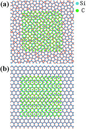 | ||
| Fig. 7 Top view of the last layer of atoms of the tip with a side length of 40 Å and the silicene with (a) dodecagonal structure and (b) honeycomb structure. | ||
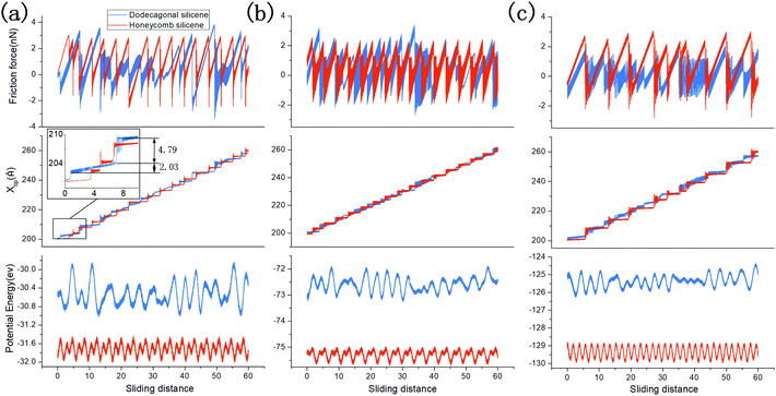
To analyse the origin of the lower friction force on dodecagonal silicene, the stick-slip process and one-dimensional potential energy surface (PES) are discussed. Fig. 8 shows the friction force versus sliding distance (upper panel), the position of the diamond tip (middle panel) and one-dimensional PES (lower panel) on planar dodecagonal silicene and planar honeycomb silicene with the tip side lengths of 20 Å (Fig. 8a), 30 Å (Fig. 8b) and 40 Å (Fig. 8c). It should be noted that the one-dimensional PES was obtained with a uniformly moving tip and its abscissa is the position of the tip instead of the x-coordinate value of the virtual atom. The stick-slip friction curve of the honeycomb structure is almost periodic with a constant peak force. Whereas, the friction force of dodecagonal is aperiodic with changing peak forces, which is expected due to its quasiperiodic structure. From Fig. 8a and b, it is not easy to directly tell which structure has a lower friction force since some of the peak forces of dodecagonal silicene are lower than the honeycomb structure and some are higher. In Fig. 8a, the one-dimensional PES for honeycomb silicene is periodic with two energy minima in each period, while the PES on the dodecagonal surface is aperiodic with varying amplitudes of potential corrugation. Generally, the depth of the potential barrier for dodecagonal silicene is larger than that of honeycomb silicene in Fig. 8a. This is opposite to our expectation about the relationship between friction and the potential corrugation, indicating that there are more dominant mechanisms such as lattice mismatch.62 As we looked further into the morphology of PES in Fig. 8a, the PES of the honeycomb structure is more compact with smaller lengths of potential corrugation. Moreover, the compact morphology of PES of the honeycomb structure made the tip stick firmly to the potential corrugation before the slip. On the contrary, the longer length of the potential corrugation and mild slope of PES for dodecagonal silicene allowed the tip to move forward slowly in the stick process and resulted in a lower mean friction force despite the higher potential barrier. The typical mild motion of the tip during the stick process on the dodecagonal surface is marked and magnified in the middle panel of Fig. 8a. Therefore, a higher potential barrier does not necessarily lead to higher friction force with different lengths of potential corrugation. Note that the density of dodecagonal silicene is quite close to that of honeycomb silicene (with a difference about 2.96%), where the longer length of potential corrugation is not a consequence of the distance between atoms but is attributed to the quasiperiodic morphology.
Filippov et al.22 (in the framework of the Tomlinson model with parameters chosen to fit the experimental results) assumed that the potential corrugation lengths differing in the periodic and quasiperiodic directions was the reason for the reduced friction, and the quasiperiodicity itself was not relevant. Although further studies23 found that Filippov's parameters did not correspond to the STM images of the experimental surface, our calculations show that the quasiperiodicity itself will cause longer potential corrugation lengths. Besides, our simulation result is in accordance with the widely reported experiments about the reduced friction of quasicrystals.15–20
Moreover, the difference between friction behaviours with varying tip sizes in Fig. 8 should be analysed for both dodecagonal and honeycomb silicene. For the honeycomb structure, the morphologies of the one-dimensional PES for various tip sizes are all featured with the same periodic length while each period has two different potential corrugations. As side length of the tip increases to 30 Å, one of the amplitudes of potential corrugation increases slightly from 0.37 eV to 0.47 eV and the other decreases from 0.33 eV to 0.20 eV; thus, the mean force decreases from 1.12 nN to 0.61 nN in Fig. 8b. The amplitude of both potential corrugations increases remarkably for the tip with a side length of 40 Å, which accounts for higher the mean friction force in Fig. 8c. In contrast, the general potential corrugations on dodecagonal silicene for different tip sizes have similar magnitude, which is different from that on the honeycomb surface.
With an increase in tip size, more relatively flat areas can be identified on the 1D PES of the dodecagonal surface in Fig. 8c. The flatter morphology of potential corrugation further contributes to the reduced friction force on the dodecagonal silicene, in addition to the mechanism of longer potential corrugation length.
4. Conclusions
In this work, we prepared monolayer dodecagonal silicene via quenching from the liquid phase between two LJ walls under lateral pressure via MD simulation. Selected area electron diffraction (SAED) showed distinct twelve-fold symmetry and verified the existence of the dodecagonal phase. The silicon atoms of the dodecagonal silicene are either three-fold or four-fold coordinated. The tensile test of the biaxial pre-strained dodecagonal silicene showed weaker strength than the honeycomb silicene and an increase in the six-fold rings during the loading process since the four-fold coordinated atom sites are less mechanically favoured. The friction behaviours with AFM were simulated on the dodecagonal and honeycomb silicene surfaces under different loads and tip sizes. For all the investigated loads and tip sizes, the dodecagonal surface always had a lower mean friction force. One-dimensional PES was employed to illuminate the mechanism behind the low friction on the quasiperiodic surface. The one-dimensional PES of the dodecagonal surface is characterized with a longer length of potential corrugation as a result of the quasiperiodic morphology. The large potential corrugation length on the dodecagonal surface facilitated the mild motion of the tip in the stick process and accounted for the lower friction. In addition to the mechanism of longer potential corrugation length, one-dimensional PES on the dodecagonal surface with a larger tip size showed a greater area with a flatter morphology, which further reduced the friction on the dodecagonal surface.Conflicts of interest
There are no conflicts of interest to declare.Acknowledgements
We are grateful to the National Supercomputer Center in Guangzhou for high-performance computational resource.References
- D. Shechtman, I. Blech, D. Gratias and J. W. Cahn, Phys. Rev. Lett., 1984, 53, 1951 CrossRef CAS.
- V. Elser and C. L. Henley, Phys. Rev. Lett., 1985, 55, 2883 CrossRef CAS PubMed.
- M. Audier, P. Sainfort and B. Dubost, Philos. Mag. B, 1986, 54, L105–L111 CAS.
- A. P. Tsai, J. Q. Guo, E. Abe, H. Takakura and T. J. Sato, Nature, 2000, 408, 537–538 CrossRef CAS.
- N. Wang, H. Chen and K. H. Kuo, Phys. Rev. Lett., 1987, 59, 1010 CrossRef CAS.
- L. Bendersky, Phys. Rev. Lett., 1985, 55, 1461–1463 CrossRef CAS PubMed.
- T. Ishimasa, H. U. Nissen and Y. Fukano, Phys. Rev. Lett., 1985, 55, 511–513 CrossRef CAS PubMed.
- R. Merlin, K. Bajema, R. Clarke, F. Y. Juang and P. K. Bhattacharya, Phys. Rev. Lett., 1985, 55, 1768–1770 CrossRef CAS PubMed.
- N. A. Wasio, R. C. Quardokus, R. P. Forrest, C. S. Lent, S. A. Corcelli, J. A. Christie, K. W. Henderson and S. A. Kandel, Nature, 2014, 507, 86–89 CrossRef CAS PubMed.
- S. Fischer, A. Exner, K. Zielske, J. Perlich, S. Deloudi, W. Steurer, P. Lindner and S. Förster, Proc. Natl. Acad. Sci. U. S. A., 2011, 108, 1810–1814 CrossRef CAS PubMed.
- X. Zeng, G. Ungar, Y. Liu, V. Percec, A. E. Dulcey and J. K. Hobbs, Nature, 2004, 428, 157–160 CrossRef CAS PubMed.
- M. Engel, P. F. Damasceno, C. L. Phillips and S. C. Glotzer, Nat. Mater., 2015, 14, 109–116 CrossRef CAS PubMed.
- R. Kamalakaran, A. K. Singh and O. N. Srivastava, Phys. Rev. B: Condens. Matter Mater. Phys., 2000, 61, 12686 CrossRef CAS.
- J. C. Johnston, S. Phippen and V. Molinero, J. Phys. Chem. Lett., 2011, 2, 384–388 CrossRef CAS.
- J.-M. Dubois, Isr. J. Chem., 2011, 51, 1168–1175 CrossRef CAS.
- E. Huttunen-Saarivirta, J. Alloys Compd., 2004, 363, 150–174 CrossRef CAS.
- D. Rouxel and P. Pigeat, Prog. Surf. Sci., 2006, 81, 488–514 CrossRef CAS.
- P. A. Thiel, Annu. Rev. Phys. Chem., 2008, 59, 129–152 CrossRef CAS PubMed.
- T. P. Yadav and N. K. Mukhopadhyay, Curr. Opin. Chem. Eng., 2018, 19, 163–169 CrossRef.
- D. A. Rabson, Prog. Surf. Sci., 2012, 87, 253–271 CrossRef CAS.
- J. Y. Park, D. F. Ogletree, M. Salmeron, R. A. Ribeiro, P. C. Canfield, C. J. Jenks and P. A. Thiel, Science, 2005, 309, 1354–1356 CrossRef CAS PubMed.
- A. E. Filippov, A. Vanossi and M. Urbakh, Phys. Rev. Lett., 2010, 104, 074302 CrossRef.
- Z. Ye, A. Martini, P. Thiel, H. H. Lovelady, K. McLaughlin and D. A. Rabson, Phys. Rev. B: Condens. Matter Mater. Phys., 2016, 93, 235438 CrossRef.
- J.-M. Dubois, Chem. Soc. Rev., 2012, 41, 6760–6777 RSC.
- Y. Zou, P. Kuczera, A. Sologubenko, T. Sumigawa, T. Kitamura, W. Steurer and R. Spolenak, Nat. Commun., 2016, 7, 12261 CrossRef CAS.
- Z. Yu, P. Kuczera, W. Steurer and R. Spolenak, Extreme Mech. Lett., 2016, 8, 229–234 CrossRef.
- B. Lalmi, H. Oughaddou, H. Enriquez, A. Kara, S. Vizzini, B. Ealet and B. Aufray, Appl. Phys. Lett., 2010, 97, 223109 CrossRef.
- B. Aufray, A. Kara, S. Vizzini, H. Oughaddou, C. Léandri, B. Ealet and G. Le Lay, Appl. Phys. Lett., 2010, 96, 183102 CrossRef.
- L. Meng, Y. Wang, L. Zhang, S. Du, R. Wu, L. Li, Y. Zhang, G. Li, H. Zhou, W. A. Hofer and H.-J. Gao, Nano Lett., 2013, 13, 685–690 CrossRef CAS PubMed.
- A. Fleurence, R. Friedlein, T. Ozaki, H. Kawai, Y. Wang and Y. Yamada-Takamura, Phys. Rev. Lett., 2012, 108, 245501 CrossRef PubMed.
- T. Aizawa, S. Suehara and S. Otani, J. Phys. Chem. C, 2014, 118, 23049–23057 CrossRef CAS.
- D. Chiappe, E. Scalise, E. Cinquanta, C. Grazianetti, B. van den Broek, M. Fanciulli, M. Houssa and A. Molle, Adv. Mater., 2014, 26, 2096–2101 CrossRef CAS.
- J. Liu, Y. Yang, P. Lyu, P. Nachtigall and Y. Xu, Adv. Mater., 2018, 30, 1800838 CrossRef.
- D. Jose and A. Datta, J. Phys. Chem. C, 2012, 116, 24639–24648 CrossRef CAS.
- S. Cahangirov, M. Topsakal, E. Aktürk, H. Şahin and S. Ciraci, Phys. Rev. Lett., 2009, 102, 236804 CrossRef CAS.
- Z. Ni, Q. Liu, K. Tang, J. Zheng, J. Zhou, R. Qin, Z. Gao, D. Yu and J. Lu, Nano Lett., 2011, 12, 113–118 CrossRef.
- L. Tao, E. Cinquanta, D. Chiappe, C. Grazianetti, M. Fanciulli, M. Dubey, A. Molle and D. Akinwande, Nat. Nanotechnol., 2015, 10, 227 CrossRef CAS.
- Z. Ni, H. Zhong, X. Jiang, R. Quhe, G. Luo, Y. Wang, M. Ye, J. Yang, J. Shi and J. Lu, Nanoscale, 2014, 6, 7609–7618 RSC.
- Y. Du, J. Zhuang, H. Liu, X. Xu, S. Eilers, K. Wu, P. Cheng, J. Zhao, X. Pi and K. W. See, ACS Nano, 2014, 8, 10019–10025 CrossRef CAS.
- J. E. Padilha and R. B. Pontes, J. Phys. Chem. C, 2015, 119, 3818–3825 CrossRef CAS.
- H. Fu, J. Zhang, Z. Ding, H. Li and S. Meng, Appl. Phys. Lett., 2014, 104, 131904 CrossRef.
- T. Botari, E. Perim, P. A. S. Autreto, A. C. T. van Duin, R. Paupitz and D. S. Galvao, Phys. Chem. Chem. Phys., 2014, 16, 19417–19423 RSC.
- D. A. Osborne, T. Morishita, S. A. Tawfik, T. Yayama and M. J. S. Spencer, Phys. Chem. Chem. Phys., 2019, 21, 17521–17537 RSC.
- Z. Sheng, S. Wu, X. Dai, T. Zhao and Y. Hao, Phys. Chem. Chem. Phys., 2018, 20, 13903–13908 RSC.
- A. Y. Galashev and K. A. Ivanichkina, Phys. Chem. Chem. Phys., 2019, 21, 12310–12320 RSC.
- S. Plimpton, J. Comput. Phys., 1995, 117, 1–19 CrossRef CAS.
- A. Stukowski, Modell. Simul. Mater. Sci. Eng., 2009, 18, 015012 CrossRef.
- F. H. Stillinger and T. A. Weber, Phys. Rev. B: Condens. Matter Mater. Phys., 1985, 31, 5262 CrossRef CAS.
- G. P. P. Pun and Y. Mishin, Phys. Rev. B: Condens. Matter Mater. Phys., 2017, 95, 224103 CrossRef.
- N. Liu, J. Hong, R. Pidaparti and X. Wang, 2D Mater., 2016, 3, 035008 CrossRef.
- B. W. Dodson, Phys. Rev. B: Condens. Matter Mater. Phys., 1986, 33, 7361 CrossRef CAS PubMed.
- A. P. Thompson, S. J. Plimpton and W. Mattson, J. Chem. Phys., 2009, 131, 154107 CrossRef PubMed.
- Y. Dong, X. Wu and A. Martini, Nanotechnology, 2013, 24, 375701 CrossRef.
- H. G. Lee, H. M. Yoon and J. S. Lee, Appl. Surf. Sci., 2019, 481, 1573–1584 CrossRef CAS.
- M. H. Muser and M. O. Robbins, Phys. Rev. B: Condens. Matter Mater. Phys., 2000, 61, 2335–2342 CrossRef CAS.
- G. He and M. O. Robbins, Phys. Rev. B: Condens. Matter Mater. Phys., 2001, 64, 035413 CrossRef.
- S. Li, Q. Li, R. W. Carpick, P. Gumbsch, X. Z. Liu, X. Ding, J. Sun and J. Li, Nature, 2016, 539, 541–545 CrossRef CAS.
- C. Qian and Z. Li, 2019, arXiv preprint arXiv:1907.00619.
- W. Steurer, Z. Kristallogr. - Cryst. Mater., 2004, 219, 391–446 CAS.
- S. P. Coleman, D. E. Spearot and L. Capolungo, Modell. Simul. Mater. Sci. Eng., 2013, 21, 055020 CrossRef.
- Q. B. Yang and W. D. Wei, Phys. Rev. Lett., 1987, 58, 1020–1023 CrossRef CAS PubMed.
- J. G. Vilhena and R. Perez, Nat. Mater., 2018, 17, 852–854 CrossRef CAS.
| This journal is © the Owner Societies 2020 |

