Methacrylate-based polymer foams with controllable connectivity, pore shape, pore size and polydispersity†
Miriam Lucia
Dabrowski
a,
Dana
Jenkins
b,
Elizabeth
Cosgriff-Hernandez
 b and
Cosima
Stubenrauch
 *a
*a
aInstitute of Physical Chemistry, University of Stuttgart, Pfaffenwaldring 55, 70569 Stuttgart, Germany. E-mail: cosima.stubenrauch@ipc.uni-stuttgart.de; Tel: +49-711-685 64470
bThe University of Texas at Austin, 107 W Dean Keeton St., Austin, 78712 Texas, USA
First published on 3rd December 2019
Abstract
Polymer foams are becoming increasingly important in industry, especially biodegradable polymer foams are in demand. Depending on the application, polymer foams need to have characteristic properties, which include connectivity and polydispersity. We show how polymer foams with tailor-made structures can be synthesized from water-in-monomer emulsions which were generated via microfluidics. As monomer we used 1,4-butanediol dimethacrylate (1,4-BDDMA). Firstly, we synthesised monodisperse open- and closed-cell poly(1,4-BDDMA) foams with either spherical or hexagonal pore shapes by varying the locus of initiation. Secondly, we were able to control the pore diameters and obtained polymer foams of both connectivities and pore shapes with pore sizes from ∼70 μm up to ∼120 μm by means of one microfluidic chip. Finally, we synthesized poly(1,4-BDDMA) foams with controllable polydispersity. Here, the mean droplet diameter was the same as that of the monodisperse counterparts in order to be able to compare the properties of the resulting polymer foams.
1. Introduction
Polymer foams have numerous advantageous properties and are therefore used in a wide range of applications such as insulation, transportation, packaging and space applications. Another emerging field is the biomedical sector.1,2 On a large scale, the porous structure is obtained by foaming polymeric materials either with the help of blowing agents or with the use of mechanical energy.3 Another method is the generation and subsequent polymerization of an emulsion4 which, so far, has been used on a small scale only. The advantage of emulsion templating is a much better control over the structure of the resulting polymer foam. For emulsion templating one can use either an oil-in-water (o/w) or a water-in-oil (w/o) emulsion. The internal phase is called the dispersed phase, while the external phase is defined as the continuous phase.5–8 Such emulsions are called high internal phase emulsions (HIPEs) if the dispersed phase is equal to or larger than 74 vol% and the resulting polymer foam is called polyHIPE.8 A common monomer for emulsion templating is styrene, often combined with the cross-linker divinylbenzene (DVB).8–13 In particular, the synthesis of both open- and closed-cell polymer foams is of great interest. Williams et al.9 were able to synthesize open- and closed-cell styrene/DVB-based polymer foams by varying the surfactant concentration. Cameron et al.11 studied the pore opening of styrene/DVB-based polymer foams via cryo-scanning electron microscopy. This method allowed them to follow the monomer to polymer conversion process, which showed that the shrinkage of the system during polymerisation leads to window formation. Quell et al.14,15 studied how the pore connectivity of styrene/DVB-based polymer foams is influenced by the locus of initiation. Qualitatively, their results are in line with those of Robinson et al.,16 who studied propylene fumarate dimethacrylate (PFDMA)-based polyHIPEs. In both cases, initiation in the monomer phase with a monomer-soluble initiator led to open-cell polymer foams, while initiation at the interface with a water-soluble initiator led to closed-cell polymer foams.14–16 Irrespective of the monomer and the initiator, all studies on emulsion templating deal with polydisperse emulsions and thus with polydisperse polyHIPEs.9,11,16 Quell et al.14,15,17,18 were the first to synthesize monodisperse w/o emulsion templated polymer foams via microfluidics. Microfluidics is a well-known technique for the generation of monodisperse gas bubbles or droplets and is used in different areas such as chemical synthesis or bioanalysis.19 Note that a system (emulsion/liquid foam/polymer foam) is considered to be monodisperse if the polydispersity of the dispersed phase (droplets/bubbles/pores) is less than 5%.20,21 In recent years22–27 microfluidic techniques have been used to synthesize scaffolds for tissue engineering. In this emerging field, bio-based, three-dimensional and highly porous matrices are used as scaffolds with the view of enhancing and facilitating tissue growth.28,29 Interesting candidates as scaffold materials are open-cell and monodisperse polymer foams.24–27,29 The interconnection of pores is necessary for the supply of nutrients,24–27,29 while a monodisperse pore architecture may facilitate a homogeneous and uniform nutrient supply and cell growth throughout the scaffold.24–27 Polymer foams for tissue engineering can be synthesised by foaming an aqueous polymer solution and subsequent cross-linking of the polymer.22–24,26,27 Alternatively, one can generate a water-in-monomer HIPE and polymerize the monomer if the monomer is hydrophobic16,25 and can thus not be foamed.30 In the first case, aqueous solutions of hydrophilic polymers like gelatin,23 polysaccharides26,27,31,32 and polyvinylalcohol24 are used. In the latter case, hydrophobic monomers like propylene fumarate diacrylate,33 propylene fumarate dimethacrylate (PFDMA),16,34–37 and 1,4-butanediol dimethacrylate (1,4-BDDMA)35,36 have been used. However, to the best of our knowledge, only polydisperse PFDMA- and 1,4-BDDMA-based scaffolds have been reported so far. The mean pore diameters of poly(PFDMA) foams and poly(1,4-BDDMA) foams are around 6 μm ± 3 μm and 14 μm ± 6 μm.35 Note that the continuous phase of the methacrylate-based water-in-monomer emulsion consists solely of the monomer. Therefore, monodisperse PFDMA-based or 1,4-BDDMA-based polymer foams are expected to have very good mechanical properties and thus be used as scaffold materials in bone tissue engineering.16,34–37Our aim was to synthesize and characterize monodisperse, methacrylate-based polymer foams with (1) open- and closed-cell pore structures, (2) different pore diameters, and (3) controllable polydispersity. We used the purchasable 1,4-BDDMA as a scouting monomer for PFDMA.35,36 Once the general concept is developed we will synthesize PFDMA and the respective polymer foams as ref. 34–37, since PFDMA-based polymer foams degrade much faster than 1,4-BDDMA-based polymer foams as will be shown in the study at hand (ESI†, Section S1). The polymer foam synthesis is based on the generation of a w/o-emulsion template via microfluidics and the subsequent polymerization of the hydrophobic monomer while retaining the template structure. (1) To obtain open- and closed-cell pore structures, we used a monomer-soluble initiator for initiation in the organic phase and a water-soluble initiator for initiation at the interface as described in ref. 14–16. (2) For the synthesis of polymer foams with different pore sizes we generated emulsion templates with different droplet sizes by varying the pressure settings and polymerized them. (3) Finally, polymer foams with controllable polydispersity were generated via the same microfluidic device but with another pressure profile for the generation of the emulsion templates as described in ref. 38.
2. Experimental part
2.1 Materials
1,4-Butanediol dimethacrylate (1,4-BDDMA, 95%), see Scheme 1 for molecular structure, containing 200 ppm–300 ppm of the inhibitor hydroquinone monomethylether (MeHQ), benzoyl peroxide (BPO, Luperox® A75, 75%) and ammonium peroxodisulfate (APS, ≥98%) were purchased from Sigma Aldrich and potassium peroxodisulfate (KPS, ≥99%) was purchased from Fluka. The technical surfactant PGPR 4125 was kindly donated by Palsgaard. Bi-distilled water (in the following called water) and NaCl were used for all emulsion templates. Ethanol was used for Soxhlet extraction. All chemicals were used as received without further purifications. A detailed study of the biodegradability of 1,4-BDMMA-based polymer foams was carried out. The results are presented in the ESI,† Section S1 (Fig. S1).2.2 Emulsion generation and polymer foam synthesis
Monodisperse and polydisperse polymer foams are synthesised in three steps: (1) the generation of a liquid w/o emulsion template via microfluidics, (2) the subsequent polymerization of the w/o template, and (3) the washing and drying of the synthesized polymer foam. (1) For the generation of the emulsion template via microfluidics, we used 1,4-BDDMA (10 g) and 10 wt% PGPR 4125 (1 g) as the continuous phase and an aqueous phase (10 g) with 5 wt% NaCl (0.5 g) as the dispersed phase. NaCl needs to be added to increase the density of the dispersed phase (ESI,† Fig. S2.1 and S2.2). Each solution was mixed with a magnetic stirrer (5 min, 500 rpm). For the synthesis of open-cell polymer foams, 2 mol% of the oil-soluble initiator (further called a monomer-soluble initiator) BPO (0.21 g) was dissolved in the continuous phase. For the synthesis of closed-cell polymer foams, 5 mol% of the water-soluble initiator KPS (0.60 g) was added to the dispersed phase. Note that Cosgriff-Hernandez et al.16,34 used APS as a water-soluble initiator which did not work for our system. The respective phase was stirred with a magnetic stirrer (20 min, 500 rpm) to ensure a homogeneous distribution of the initiator. The masses of the surfactant, salt and initiator were calculated with respect to the mass or amount (mol) of the 1,4-BDDMA monomer. All emulsion templates were generated via microfluidics (Section 2.3). The final emulsion was collected in a glass tube (VWR, 44.6 mm × 14.65 mm, ∅inner ≈ 1.3 cm). Due to gravity the droplets sedimented and ordered themselves in a hexagonal closed-packed structure. Simultaneously, a continuous 1,4-BDDMA excess phase was formed on top of the sample. A nearly transparent excess phase and a flat emulsion surface indicated the end of the droplet sedimentation process. After removing the excess phase, one obtained a w/o HIPE with a dispersed phase volume of 74%. The final emulsion height was ∼1 cm. The emulsion was then polymerized for 6 h via UV-polymerization by placing the emulsion template in the centre between two UV-lamps (Heraeus MH-Modul 250 W Z4 XL, spectral range from ∼250 nm–500 nm) which face each other. Then, the glass tube was broken to remove the polymer foam. The polymer foam was purified via Soxhlet extraction with ethanol at 100 °C for at least 12 h and dried in an oven at 70 °C for ∼72 h to remove residual water.2.3 Microfluidic device for emulsion generation
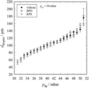
The main part of a microfluidic device is the microfluidic chip. For the generation of each emulsion template we used a glass chip from Dolomite with a hydrophobic coating. We only used the flow-focussing chip geometry (X-junction) with a constriction of a depth of 100 μm and a width of 105 μm. The channel depth is 100 μm and the channel width is 300 μm. The two phases were placed in 100 ml glass bottle from Schott equipped with a GL45 cap from Vaplock, which was connected with the pressure controller and the microfluidic chip. The latter was connected by FEP tubings (1/16′′ × 0.5 mm) from Dolomite. The flow of both phases was pressure controlled with an Elveflow OB1 MKIII+ pressure controller. The pressure of nitrogen was set with the software Elveflow Smart Interface provided by Elveflow. For the generation of monodisperse droplets, we used the “constant” pressure profile (within the software) for both phases. The continuous phase was pumped through the two outer inlet channels and the dispersed phase was pushed through the inner inlet channel. By selecting an appropriate pressure setting for the dispersed phase (Section 3.1 and Fig. 1), droplets were formed at the chip constriction. The final emulsion left the microfluidic chip through an outlet channel. A Nikon SMZ745T optical microscope equipped with a Mikroton EoSens CL MC1362 high speed camera was used to follow the droplet generation. The microfluidic chip was placed on a Dolomite mitos microscope stage which was connected via an optical fiber with a Schott KL 1500 Compact light source. Microscope pictures were taken by using the software MotionBLITZ® Director2 Kit from Mikroton.Calibration is necessary to determine the pressure range which can be used to produce droplets of uniform sizes with different diameters. Here, the used quantities of substances were double of quantities shown in Section 2.2, a glass chip with and without a hydrophobic coating was used and the pressure for the continuous phase was kept constant at 50 mbar, while the pressure of the dispersed phase was stepwise varied in order to generate different sizes of uniform droplets (Section 3.1 and Fig. 1). At each pressure combination of the two phases, a micrograph of the monolayer of the emulsion was taken.
The final monodisperse emulsion templates were generated following the same procedure. The pressure of the continuous phase was fixed at 50 mbar, while the selected pressure setting for the dispersed phase depended on the droplet diameter (Fig. 1). For the generation of the final emulsion templates with a controllable polydispersity, the same experimental setup was used but we changed the pressure profile of the dispersed phase to a “sine” profile. Thus, the pressure of the dispersed phase ran periodically through a sine curve, beginning from a minimum over a maximum back to a minimum. The pressure of the continuous phase was also kept constant at 50 mbar. One period τ took 10 s (Fig. 7, top left). In the case of the BPO-containing emulsion the pressure of the dispersed phase was varied from 33 mbar to 45 mbar (Fig. 7, top right), therefore the mean pressure of the dispersed phase was ∼39 mbar. In the case of the KPS-containing emulsion the pressure was varied from 34 mbar to 47 mbar, the mean pressure of the dispersed phase was ∼41 mbar. The following steps were the same as those used for the generation of the monodisperse emulsion templates. The characterization of the final monodisperse and polydisperse emulsion templates is described in Sections 2.4 and 2.5.
2.4 Optical microscopy and scanning electron microscopy (SEM)
Emulsions were characterized via optical microscopy using the set-up described in Section 2.3. Here, one droplet of the w/o emulsion was collected on a microscope glass slide (76 mm × 52 mm × 1 mm) that was rotated carefully to isolate the water droplets, which facilitates the determination of droplet diameters. Finally, a microscope picture (resolution: 1280 × 1024) of the monolayer was taken. Note that the monolayers with very large droplets (at high dispersed phase pressures, beginning at ∼48 mbar) had to be diluted in the continuous phase earlier to isolate the water droplets. The latter was not necessary for taking microscope pictures of the monolayers. The mean droplet diameters were determined as described in Section 2.5. Polymer foams were characterized via scanning electron microscopy (SEM). The samples were broken or cut horizontally and vertically with a razor blade into small specimens after being frozen in liquid nitrogen to protect the structure from frictional heat. Please note that a few samples broke vertically already during the removal of the glass tube. The specimens were fixed on a SEM specimen stub with a conductive silver glue from Plano (Acheson 1415) and coated with carbon (from Plano) in an Emitech K550 sputter coater. The morphology of the polymer foams was characterized with a CamScan CS44 (1) scanning electron microscope (SEM) using Secondary Electron Imaging (SEI) and a voltage of 5 kV (SEM pictures in Fig. 3, 5 and 8). SEM pictures were taken by using the software Edax Genesis at a resolution of 1024 × 800. Additionally, a Zeiss Gemini (2) SEM 500 SEM using SEI and a voltage of 3 kV (SEM pictures in Fig. 4 and 6) was used to characterize the fine structure of polymer foams at higher magnifications (i.e. >500×). The user interface is called SmartSEM. The pore diameters, window diameters and skin thicknesses were determined with SEM pictures of polymer foams made with SEM (1) CamScan CS44 SEM by using the original micrographs. Afterwards, the software ImageJ was used to improve the contrast and brightness of the SEM pictures in Fig. 3, 5 and 8 and to add the scale bars into all plain micrographs.2.5 Determination of droplet diameters, pore diameters, window diameters, skin thicknesses and PDI's
The mean droplet and pore diameters were determined as follows. A fixed number of droplet and pore areas were determined in the original micrographs by using the software ImageJ. The droplet areas Adroplet were determined automatically by the software or manually by encircling each droplet in the two-dimensional microscope picture(s) of the monolayer of the emulsion templates. The pore areas Apore were determined by encircling each pore manually in the two-dimensional SEM pictures of specimens of polymer foams (made with SEM (1)). The mean droplet and pore diameters ddroplet/pore were calculated with eqn (1). The arithmetic mean![[d with combining macron]](https://www.rsc.org/images/entities/i_char_0064_0304.gif) droplet/pore (eqn (2)) and the standard deviation of the mean droplet or pore diameter σ (eqn (3)) were then calculated both for a total number of droplets and pores ntotal of 200.
droplet/pore (eqn (2)) and the standard deviation of the mean droplet or pore diameter σ (eqn (3)) were then calculated both for a total number of droplets and pores ntotal of 200. | (1) |
 | (2) |
 | (3) |
 | (4) |
For calibration, the areas of 200 droplets for each monolayer were determined and all pressure combinations, which lead to a monolayer with a PDI of ≤5%, were considered. The calibration was then repeated twice and a mean diameter of 600 droplets with standard deviation (Fig. 1) and PDI was calculated. For the calculation of the mean droplet diameter ddroplet with PDI of the final emulsion templates the areas of 200 droplets for each monolayer within the microscope pictures (at 5× magnification) were determined and for the calculation of the mean pore diameter dpore with PDI the areas of 200 representative pores in different areas of the sample (horizontally and vertically cut) within the SEM pictures (at 100× magnification) were determined. For the pore size determination, both spherical pores (BPO-initiated polymerization) and hexagonal pores (KPS-initiated polymerization) were treated as spheres.
ImageJ was also used for the determination of the mean window diameters (BPO-initiated polymerization) and the mean skin thicknesses at different locations in the sample (KPS-initiated polymerization) in the SEM pictures made with SEM (1). For this purpose, only adjacent pores were taken into account. The window diameters were determined in the same way as the mean droplet and pore diameters. Note that some parts of the windows are clearly open, while other parts show thin remains of polymeric skins. For the determination of the window diameters, only the areas of clearly open parts of 50 windows were analysed with SEM pictures (at 250× magnification). For measuring the thicknesses of the skin, which surrounds each pore of the closed-cell polymer foams, the mean thickness and its standard deviation were measured at two locations using the SEM pictures (at 500× magnification). 50 skin thicknesses at the vertex (area between three pores in a two-dimensional SEM picture) and 50 skin thicknesses at the estimated thinnest point between two adjacent pores were determined.
3. Results and discussion
3.1 Generation of monodisperse water-in-1,4-BDDMA emulsion templates
It can be seen that there is a nearly linear trend between the droplet diameter and pressure of the dispersed phase. Without any initiator we generated droplets from 54 μm ± 7 μm (PDI = 13%) to 176 μm ± 4 μm (PDI = 3%). The same droplet sizes (54 μm ± 5 μm, PDI = 8% and 181 μm ± 20 μm, PDI = 11%) were obtained in the presence of the initiator BPO, while in the presence of the initiator KPS a slight drift towards smaller droplet sizes was observed with increasing pdp (57 μm ± 3 μm, PDI = 6%, and 157 μm ± 3 μm, PDI = 2%). However, the values are still within the experimental error. In general, the lower boundary for droplet generation is determined by both the microfluidic chip constriction and our optical microscope. Due to the limited magnification of the microscope very small droplets cannot be characterized. The upper boundary for the droplet generation is the droplets’ own weight.
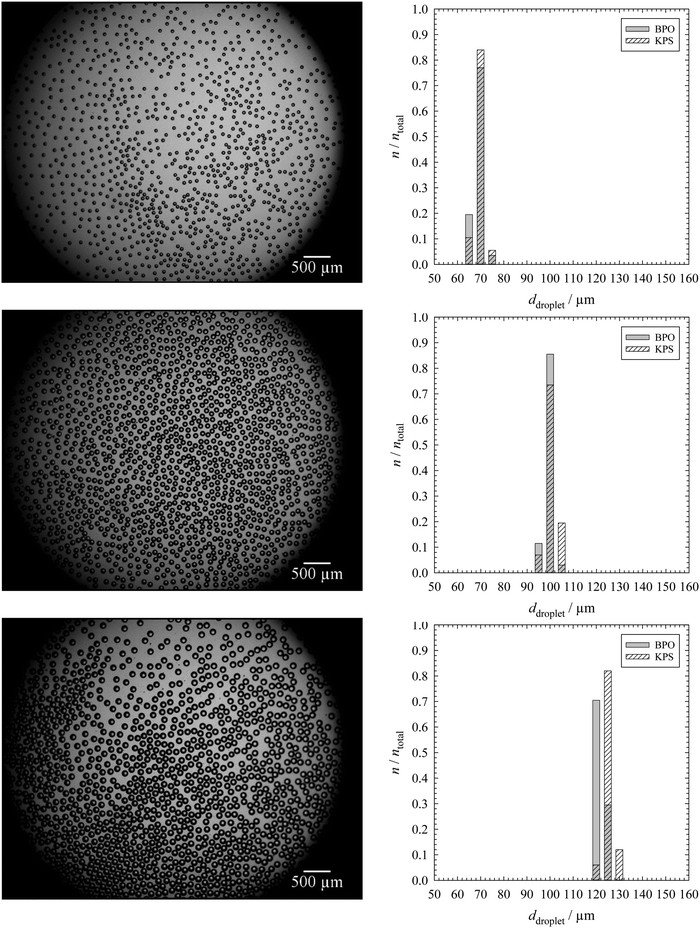 | ||
| Fig. 2 Microscope pictures of monolayers of monodisperse emulsion templates with droplet diameters of around 70 μm (top), 100 μm (middle) and 120 μm (bottom) for emulsion templates containing 2 mol% BPO in the continuous phase (left) and the corresponding droplet size distributions with ntotal = 200 (right). The droplet size distribution for the KPS-containing samples is also shown (right), while the microscope pictures of the monolayers containing 5 mol% KPS in the dispersed phase are shown in the ESI† (Fig. S3). The continuous phase of the emulsion template consisted of 1,4-BDDMA containing 10 wt% PGPR 4125, the dispersed phase was an aqueous phase containing 5 wt% NaCl. The masses of the surfactant, salt and initiator were calculated with respect to the mass or amount (mol) of the monomer 1,4-BDDMA. | ||
The left-hand side of Fig. 2 shows the resulting monolayers with increasing droplet diameters from top to bottom. In this case, the template contained BPO as the initiator. In case KPS was used, the monolayers look nearly the same (ESI,† Fig. S3). The right-hand side of Fig. 2 shows the corresponding droplet size distributions of BPO- and KPS-containing templates. Both the microscope picture and the droplet size distributions reveal a high monodispersity of droplets. The mean droplet diameters with standard deviation and the PDI of the BPO- and KPS-containing templates are listed in Tables 1 and 2. The mean droplet diameters of our templates do not match exactly with our calibration curve for a given pressure combination but are in line with the calibration within the experimental error.
![[d with combining macron]](https://www.rsc.org/images/entities/i_char_0064_0304.gif) droplet and PDIs of the monolayers of the emulsion templates containing BPO as initiator as well as the mean pore diameters
droplet and PDIs of the monolayers of the emulsion templates containing BPO as initiator as well as the mean pore diameters ![[d with combining macron]](https://www.rsc.org/images/entities/i_char_0064_0304.gif) pore, its PDIs and the mean window diameters
pore, its PDIs and the mean window diameters ![[d with combining macron]](https://www.rsc.org/images/entities/i_char_0064_0304.gif) window of all three open-cell poly(1,4-BDDMA) foams
window of all three open-cell poly(1,4-BDDMA) foams
| Emulsion template | Polymer foam | |||
|---|---|---|---|---|
![[d with combining macron]](https://www.rsc.org/images/entities/i_char_0064_0304.gif) droplet/μm
droplet/μm |
PDI/% |
![[d with combining macron]](https://www.rsc.org/images/entities/i_char_0064_0304.gif) pore/μm
pore/μm |
PDI/% |
![[d with combining macron]](https://www.rsc.org/images/entities/i_char_0064_0304.gif) window/μm
window/μm |
| 66 ± 2 | 3 | 72 ± 4 | 6 | 10 ± 2 |
| 97 ± 1 | 2 | 100 ± 5 | 5 | 12 ± 3 |
| 119 ± 2 | 1 | 126 ± 8 | 6 | 16 ± 3 |
![[d with combining macron]](https://www.rsc.org/images/entities/i_char_0064_0304.gif) droplet and PDIs of the monolayers of the emulsion templates containing KPS as an initiator as well as the mean pore diameters
droplet and PDIs of the monolayers of the emulsion templates containing KPS as an initiator as well as the mean pore diameters ![[d with combining macron]](https://www.rsc.org/images/entities/i_char_0064_0304.gif) pore, its PDIs and the mean thicknesses of the skins
pore, its PDIs and the mean thicknesses of the skins ![[t with combining macron]](https://www.rsc.org/images/entities/i_char_0074_0304.gif) skin of all three closed-cell poly(1,4-BDDMA) foams
skin of all three closed-cell poly(1,4-BDDMA) foams
| Emulsion template | Polymer foam | |||
|---|---|---|---|---|
![[d with combining macron]](https://www.rsc.org/images/entities/i_char_0064_0304.gif) droplet/μm
droplet/μm |
PDI/% |
![[d with combining macron]](https://www.rsc.org/images/entities/i_char_0064_0304.gif) pore/μm
pore/μm |
PDI/% |
![[t with combining macron]](https://www.rsc.org/images/entities/i_char_0074_0304.gif) skin/μm
skin/μm |
| 67 ± 2 | 3 | 74 ± 2 | 3 | 0.7 ± 0.2 |
| 98 ± 2 | 2 | 107 ± 5 | 5 | 1.1 ± 0.4 |
| 122 ± 2 | 1 | 127 ± 5 | 4 | 1.1 ± 0.5 |
3.2 Monodisperse poly(1,4-BDDMA) foams
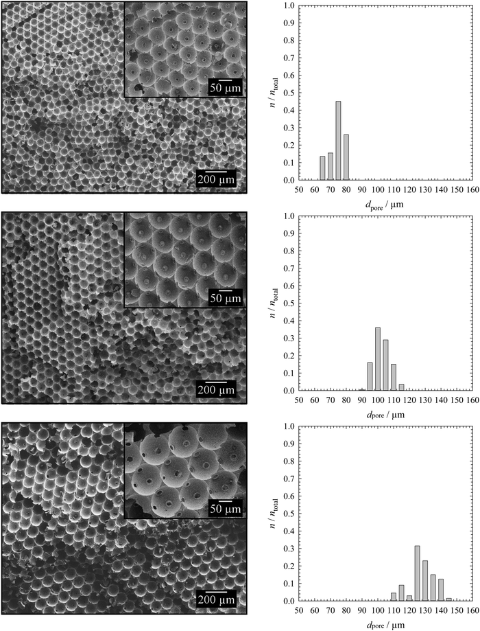
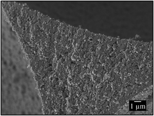
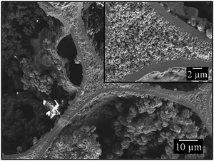
To synthesize monodisperse polymer foams with different pore sizes the emulsion templates (Fig. 2) were subsequently polymerized and characterized as described in Sections 2.2 to 2.5. Initiation with BPO in the continuous phase led to open-cell poly(1,4-BDDMA) foams (Fig. 3), while initiation with KPS at the interface led to closed-cell poly(1,4-BDDMA) foams (Fig. 5).The polymer foam seen in Fig. 3 (top left) has a closed-packed structure of spherical pores with a mean pore diameter of 72 μm ± 4 μm. In some parts of the sample the pores are highly ordered, while in other parts there are not. The degree of order of the pores increases from the outside to the inside of the sample. According to the SEM picture, to the pore size distribution (Fig. 3, top right), and to the calculated PDI (Table 1) the polymer foam is monodisperse. To sum up, the polymerization of a liquid emulsion template with a mean droplet diameter of 66 μm ± 2 μm and a PDI of 3% led to a polymer foam with a mean pore diameter of 72 μm ± 4 μm and a PDI of 6%. Comparing the values one sees that the pore diameter is in the same range as the droplet diameter. The slightly higher PDI of the polymer foams was probably caused by an irregular, not perfect equatorially broken sample. Additionally, in some parts of the polymer foam the closed-packed pores of the polymer foam are interconnected via so-called windows, while in other parts they are not. The mean window diameter of this sample is 10 μm ± 2 μm. Finally, a closer look at the pore walls (Fig. 4) reveals an additional porosity. We will come back to this point further below.
If one compares the open-cell poly(1,4-BDDMA) foam in Fig. 3 (top, left) with the open-cell styrene/DVB-based polymer foams in ref. 14 and 15 one sees an agreement related to the pore size, the spherical pore shape as well as the window formation. The SEM pictures of the other two samples tell the same story but for larger pore diameters. The mean pore diameters of 100 μm ± 5 μm with a PDI of 5% (Fig. 3, middle) and 126 μm ± 8 μm with a PDI of 6% (Fig. 3, bottom) were obtained from the mean droplet diameters of 97 μm ± 1 μm (PDI = 2%) and 119 μm ± 2 μm (PDI = 1%). The window diameters are 12 μm ± 3 μm and 16 μm ± 3 μm, respectively. Thus the window diameter increases simultaneously with the pore diameter (Table 1). The spherical and in most cases interconnected pore structure of all poly(1,4-BDDMA) foams is a result of the locus of initiation. If the monomer-soluble initiator BPO is used the initiation of 1,4-BDDMA takes place in the continuous phase. During polymerization the viscosity of the continuous phase increases. Eventually windows are formed at the contact point of two closed-packed droplets caused by the shrinkage of the continuous phase. In case neighbouring droplets of the emulsion template do not directly contact or the emulsion templates are not closed-packed, no windows form and we observe a more or less thick polymeric matrix between two pores. There are two possible explanations for the additional porosity of the pore walls. Firstly the presence of a surfactant (10 wt% relating to 1,4-BDDMA) and secondly the presence of emulsified water droplets in the continuous phase which are both removed during Soxhlet extraction. While the first explanation is obvious, we have no experimental evidence for the second one yet.
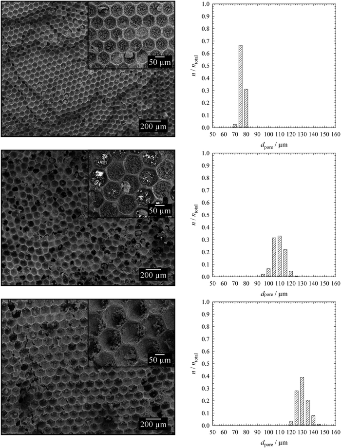
The first polymer foam (Fig. 5, top left) has a closed-packed structure of hexagonal pores which are highly ordered in many parts of the sample. The mean pore diameter of the polymer foam is 74 μm ± 2 μm, which is equal to the droplet diameter of 67 μm ± 2 μm. To simplify the comparability with the spherical pores (BPO-initiated polymerization), the hexagonal pores were treated as spheres and their diameter was calculated as described in Section 2.5. The corresponding pore size distribution is illustrated in Fig. 5 (top right), the PDI is listed in Table 2. Both the pore size distribution and the PDI confirm the monodispersity of the poly(1,4-BDDMA) foam. Interestingly, the pores are filled with small particles. In contrast to the open-cell poly(1,4-BDDMA) foams, every pore is surrounded by a skin. The skin has a unique thickness of 1.0 μm ± 0.5 μm, while the total thickness of the pore walls varies: first, the pore walls are the thinnest between two pores. In some cases the thinnest part of the pore wall at the contact point between two pores consists solely of the skin (i.e. of two skins, which are merged), while in other cases a porous inner layer is observed between two skins (Fig. 6). This additional layer appears if the neighbouring droplets of the emulsion template do not directly contact or if the polymer foam is not closed-packed which has, in turn, an impact on the pore wall thickness. The structure of this porous layer is very similar to that found for the BPO-initiated polymer foams (see Fig. 4 for comparison). In summary, the pore walls of the KPS-initiated polymer foams are layered and got thicker the more one approaches the vertex as is clearly seen in Fig. 6. Note that for determining the thickness of the pore skin we only analysed the thinnest part of the pore wall between two adjacent pores which has no inner layer. We will come back to this point further below.
Comparing the closed-cell poly(1,4-BDDMA) foam in Fig. 5 (top, left) with the results of the styrene/DVB-based polymer foams in ref. 14, 15, 17, and 18 one sees that the structural properties including the pore size, the hexagonal shape, the formation of particles in the pores as well as the skin formation and the porous pore walls do agree with those of Quell et al.14,15,17,18 The SEM pictures in Fig. 5 show that the closed-cell pore structures, the hexagonal shapes and the presence of small particles inside the pores do not depend on the pore size. The same independence was found for the thickness of the skin, while the thickness of the pore wall again depends on the location (between two pores vs. vertex). Characteristic details of the KPS-initiated poly(1,4-BDDMA) foams with larger sizes (Fig. 5, middle left, bottom left) can be found in Table 2.
In case of interfacial initiation with KPS, we hypothesize that the resulting polymer foam structure is caused by a couple of different mechanisms that occur either simultaneously or consecutively. Since there is a measurable solubility of the monomer in water polymerisation of the monomer inside the water droplets leads to the formation of small particles on the pore walls and within the pores. The unique distribution of these particles is interesting. Therefore, we assume that the particles are movable as long as they are encircled by water. At the same time the polymerization is initiated at the interface by a peroxodisulfate radical. As a result, a polymer skin around the droplet is formed in which the solubility of possibly emulsified water droplets as well as the surfactant is lower compared to the monomer phase. These water droplets and the surfactant diffuse to the interior of the pore walls, which causes the additional porosity in the middle of the pore walls after Soxhlet extraction (Fig. 6). The constant and homogeneous skin thickness observed in all samples can be explained by structure-independent polymerization kinetics. Once a certain polymerisation degree is reached – and this happens obviously always after the same time – water and the surfactant are expelled leading to dense outer polymer-rich and porous inner polymer-poor layers. The droplet deformation from a sphere to a hexagon indicates that the skin was elastic until the polymerisation was finished. Initiation of the polymerization at the interface leads to polymerization of the continuous phase from the monomer/water interface to the interior of the films until the continuous phase is completely polymerized. We assume that skin formation is faster than the shrinkage of the continuous phase which, in turn, prevents hole formation.
However, there is still one open question: Which mechanism leads to the deformation of the droplets? Quell et al.14,15,17,18 synthesized closed-cell polystyrene/-DVB foams via interfacial initiation of the polymerisation and obtained polymer foams of the same structural properties as the interfacial initiated 1,4-BDDMA-based polymer foams. They hypothesised that the hexagonal shape was a result of an osmotic transport within the continuous phase caused by different reaction kinetics of styrene and DVB, which lead to a concentration gradient.14,18 Quell et al.14,15,17,18 argued that a second monomer is the prerequisite for the formation of hexagonal pores. However, the poly(1,4-BDDMA) foams were synthesized from one monomer only and thus the osmotic transport cannot be the reason for the conversion of a spherical droplet into a hexagonal pore. Preliminary experiments with the water-soluble initiator APS may help in understanding the deformation of droplets. One of our first poly(1,4-BDDMA) foams had a porous structure with spherical pores that are not closed-packed (ESI,† Fig. S2.2). Therefore, we assume a relation between the closed-packed pore structure and the hexagonally shaped pores. We keep searching for an explanation.
3.3 Poly(1,4-BDDMA) foams with controllable polydispersity
As mentioned in the introduction, most polymer foams are polydisperse.9,11,16 Moreover, the polydispersity can be controlled only to a very limited extent. If one wants to study the influence of polydispersity on the properties of polymer foams it needs to be tunable. In addition, if one wants to compare the properties of monodisperse and polydisperse polymer foams the latter must have the same mean pore diameter. To fill this gap, we synthesized polydisperse counterparts of the monodisperse poly(1,4-BDDMA) foams with both initiators. However, the pore sizes of poly-1,4-BDDMA foams synthesized via the polymerization of polydisperse w/o-emulsions generated in a speed mixer are about 14 μm ± 6 μm.35 Hence, these dimensions are not comparable with the pore dimensions of the monodisperse poly(1,4-BDDMA) foams synthesized in the present study which are between 70 μm and 120 μm as described in Section 3.2. Andrieux et al.38 developed a method for the generation of bubbles with controllable polydispersity which we used to generate droplets of the same mean diameter but different polydispersities. We used the same experimental setup as in Section 3.2 and changed the pressure profile of the dispersed phase with the software as described in Section 2.3. Thus, monodisperse droplets with different diameters were generated periodically (Fig. 7, top) leading to a polydisperse sample. The periodically changing pressure was set such that droplets with diameters of 95 μm ± 25 μm were generated.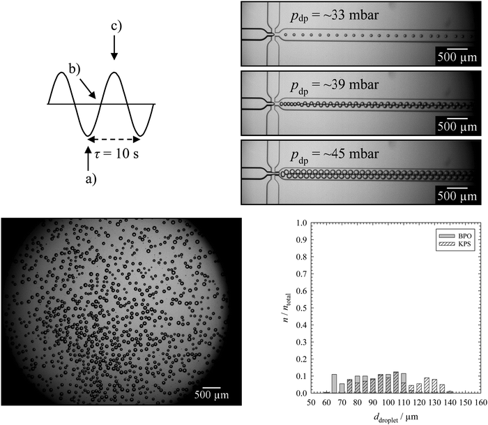 | ||
| Fig. 7 Schematic drawing of a sine profile (top left), microscope pictures of the droplet generation inside the microfluidic chip during one period with different pressures of the dispersed phase pdp (top right). A microscope picture of the resulting liquid monolayer containing 2 mol% BPO in the continuous phase (bottom, left) and the corresponding droplet size distributions of monolayers containing either BPO or KPS with ntotal = 200 (bottom, right) are also shown. A microscope picture of the KPS-containing monolayer is placed in the ESI,† Fig. S4. The continuous phase of the emulsion templates consisted of 1,4-BDDMA containing 10 wt% PGPR 4125, the dispersed phase was an aqueous phase containing 5 wt% NaCl. The masses of the surfactant, salt and initiator were calculated with respect to the mass or amount (mol) of the monomer 1,4-BDDMA. | ||
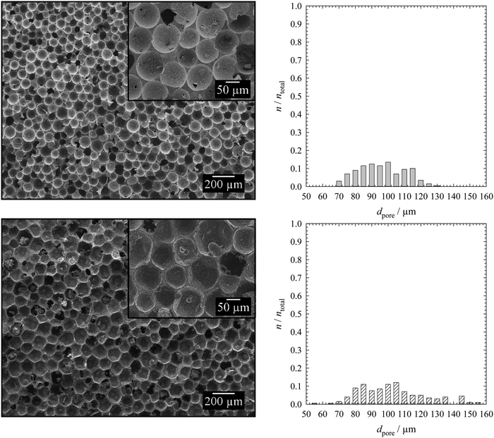
The mean droplet diameter of the BPO-containing monolayer in Fig. 7 is about 87 μm ± 15 μm with a PDI of 17%. The corresponding KPS-containing emulsion template looks similar but with a few larger droplets (ESI,† Fig. S4) and thus with a mean droplet diameter of 102 μm ± 18 μm and a PDI of 18%. The droplet diameters shown in Fig. 7 and listed in Table 3 are slightly different due to the following reasons. Firstly, the time of one period τ was set equal to 10 s, while it only took a few seconds to collect a monolayer of water droplets. Secondly, it is not possible to collect a monolayer of water droplets of exactly one period τ. Thus, the monolayer did not contain all droplet diameters but a larger number of the same droplet diameters (Fig. 7, bottom left). However, this misconception is of no relevance for the pore sizes of the polymer foam since sample collection for the subsequent polymerization took >10 s. Fig. 8 shows the corresponding polydisperse BPO-initiated poly(1,4-BDDMA) foam (top left) and the polydisperse KPS-initiated poly(1,4-BDDMA) foam (bottom left) with plots of the corresponding pore size distributions listed in the same order (right).
![[d with combining macron]](https://www.rsc.org/images/entities/i_char_0064_0304.gif) droplet and PDIs of monolayers of the emulsion templates containing either BPO or KPS as an initiator as well as the mean pore diameters
droplet and PDIs of monolayers of the emulsion templates containing either BPO or KPS as an initiator as well as the mean pore diameters ![[d with combining macron]](https://www.rsc.org/images/entities/i_char_0064_0304.gif) pore and its PDIs. For BPO-initiated poly(1,4-BDDMA) foams the mean window diameters
pore and its PDIs. For BPO-initiated poly(1,4-BDDMA) foams the mean window diameters ![[d with combining macron]](https://www.rsc.org/images/entities/i_char_0064_0304.gif) window are also listed, while for KPS-initiated poly(1,4-BDDMA) foams the mean thicknesses of the skin
window are also listed, while for KPS-initiated poly(1,4-BDDMA) foams the mean thicknesses of the skin ![[t with combining macron]](https://www.rsc.org/images/entities/i_char_0074_0304.gif) skin are given
skin are given
The SEM picture of the BPO initiated poly(1,4-BDDMA) foam (Fig. 8, top left) shows a closed-packed, non-ordered structure of spherical pores with a mean pore diameter of 94 μm ± 14 μm and a PDI of 15%. Comparing the droplet diameter (87 μm ± 15 μm) with the pore diameter, one clearly sees that neither the pore size nor the pore shape nor the PDI charged significantly. The mean window diameter is 11 μm ± 3 μm and thus comparable with that of the monodisperse counterparts. The other SEM picture in Fig. 8 (bottom left) shows the KPS initiated poly(1,4-BDDMA) foam with a closed-packed and non-ordered structure of non-spherical but rather hexagonal pores. In this case, the mean pore diameter of 101 μm ± 20 μm is nearly the same as the mean droplet diameter of 102 μm ± 18 μm. The mean skin thickness was found to be 1.3 μm ± 0.6 μm which again is very close to the value found for the monodisperse counterparts. According to Andrieux et al.,38 the PDI can be tuned by varying the amplitude and the period which we will use to produce polymer foams of different polydispersities in future studies.
The capability to generate polydisperse droplets of the same mean diameter as the monodisperse emulsion templates and the fact that the resulting pore sizes correspond to the droplet sizes enable us to compare the properties of monodisperse emulsion templates and monodisperse polymer foams with their polydisperse counterparts. First and foremost we will focus on the mechanical properties of the resulting polymer foams with the view of finding a relationship between the structure and properties. If we find such a relationship we will have the means to study the influence of one structural parameter at a time on the properties of polymer foams, namely the polydispersity.
4. Conclusions and outlook
This paper deals with the synthesis and characterization of polymer foams with tailor-made structures. As the monomer we used hydrophobic 1,4-butanediol dimethacrylate (1,4-BDDMA). The polymer foam synthesis is based on the generation and polymerisation of w/o emulsion templates via microfluidics. By varying the initiator or adjusting the pressure settings during template generation, we were able to synthesize polymer foams with different (1) pore connectivities and pore shapes, (2) pore sizes, and (3) polydispersities. (1) We changed the pore connectivity and the pore shapes of the monodisperse poly(1,4-BDDMA) foams by varying the initiator and thereby the locus of initiation as described in ref. 14–16 and 18 at a constant pore diameter of around 70 μm. Monomer phase initiation with the monomer-soluble initiator BPO led to open-cell poly(1,4-BDDMA) foams with spherical pores, while interfacial initiation with the water-soluble initiator KPS led to closed-cell poly(1,4-BDDMA) foams with hexagonal pores. Furthermore, in the latter case each pore was surrounded by a polymer skin of a unique thickness. Therefore, our results are in agreement with those of Quell et al.14,15,17,18 and qualitatively with those of Robinson et al.16 (2) In analogy to Quell et al.,14,15,17,18 we started with a pore diameter of about 70 μm. Additionally, we were able to increase the pore diameters by increasing the pressure settings of the dispersed phase. With this approach we synthesized open- and closed-cell poly(1,4-BDDMA) foams with around 100 μm and 120 μm pore diameters, while retaining the pore connectivities and the pore shapes. Thus, between 70 μm and 120 μm the droplet diameter had no effect on the resulting polymer foam structure. The mean window diameter in the monodisperse open-cell poly(1,4-BDDMA) foams increased with the pore diameters, while the skin thickness in the monodisperse closed-cell poly(1,4-BDDMA) foams was unchanged, i.e. it was independent of the pore diameter. (3) The last part of this paper deals with the synthesis of poly(1,4-BDDMA) foams with tunable polydispersity via microfluidics in order to synthesize a polydisperse counterpart to the monodisperse samples. The mean pore diameter, the mean window diameter in the open-cell poly(1,4-BDDMA) foam as well as the mean skin thickness in the closed-cell poly(1,4-BDDMA) foam were in line with the values of the monodisperse polymer foams, which allowed us to compare both polymer foams. In a follow-up study we will study the influence of the polydispersity on the mechanical properties of the polymer foams and will compare the results with those obtained for the monodisperse counterparts. Furthermore, we are currently working on the synthesis of poly(1,4-BDDMA) foams with much larger pore sizes and higher pore wall porosities via the polymerization of foamed emulsions.30,39,40 It goes without saying that the mechanical properties of these polymer foams will be studied as well. The final goal is to have a broad variety of different structures to get an overall picture about structure–property relations of this material. Finally, we are planning to synthesise the same set of materials using PFDMA as the monomer to generate biodegradable polymer foams.Conflicts of interest
The authors declare no conflicts of interests.Acknowledgements
We acknowledge W. Drenckhan, M. R. Buchmeiser, and L. Koch for helpful discussions. We thank Palsgaard for donating PGPR 4125 and we thank A. Fels for the opportunity to use the SEM. Additionally, we want to thank Y. Qawasmi for analysing two polymer foams with Zeiss GeminiSEM 500.References
- P. S. Liu and G. F. Chen, Porous Materials. Processing and Applications, Elsevier, Oxford, 2014 Search PubMed.
- B. E. Obi, Polymeric Foams Structure–Properties–Performance: A Design Guide, Elsevier, Oxford, Cambridge, 2018 Search PubMed.
- M. O. Okoroafor and K. C. Frisch, Introduction to Foam and Foam Formation, in Handbook of Plastic Foams, ed. A. H. Landrock, Noyes Publications, Saddle River, NJ, 1995, ch. 1, pp. 1–10 Search PubMed.
- N. J. Mills, Polymer Foams Handbook, Elsevier, Oxford, 2007 Search PubMed.
- B. P. Binks, Modern Aspects of Emulsion Science, The Royal Society of Chemistry, Cambridge, 1998 Search PubMed.
- L. L. Schramm, Emulsions, Foams and Suspensions: Fundamentals and Applications, Wiley-VCH, Weinheim, 2005 Search PubMed.
- T. F. Tadros, Emulsion Formation and Stability, Wiley-VCH, Weinheim, 2013 Search PubMed.
- M. S. Silverstein, Prog. Polym. Sci., 2014, 39, 199 CrossRef CAS.
- J. M. Williams and D. A. Wrobleski, Langmuir, 1988, 4, 656 CrossRef CAS.
- P. Hainey, I. M. Huxham, B. Rowatt and D. C. Sherrington, Macromolecules, 1991, 24, 117 CrossRef CAS.
- N. R. Cameron, D. C. Sherrington, L. Albiston and D. P. Gregory, Colloid Polym. Sci., 1996, 274, 592 CrossRef CAS.
- A. Menner, R. Powell and A. Bismarck, Soft Matter, 2006, 2, 337 RSC.
- V. O. Ikem, A. Menner and A. Bismarck, Soft Matter, 2011, 7, 6571 RSC.
- A. Quell, B. de Bergolis, W. Drenckhan and C. Stubenrauch, Macromolecules, 2016, 49, 5059 CrossRef CAS.
- A. Quell, T. Sottmann and C. Stubenrauch, Langmuir, 2017, 33, 537 CrossRef CAS PubMed.
- J. L. Robinson, R. S. Moglia, M. C. Stuebben, M. A. P. McEnery and E. Cosgriff-Hernandez, Tissue Eng., Part A, 2014, 20, 1103 CrossRef CAS PubMed.
- A. Quell, J. Elsing, W. Drenckhan and C. Stubenrauch, Adv. Eng. Mater., 2015, 17, 604 CrossRef CAS.
- A. Quell, S. Heitkam, W. Drenckhan and C. Stubenrauch, Chem. Phys. Chem., 2017, 18, 451 CrossRef CAS PubMed.
- G. M. Whitesides, Nature, 2006, 442, 368 CrossRef CAS PubMed.
- W. Drenckhan and D. Langevin, Curr. Opin. Colloid Interface Sci., 2010, 15, 341 CrossRef CAS.
- A. Maestro, W. Drenkhan, E. Rio and R. Höhler, Soft Matter, 2013, 9, 2531 RSC.
- K.-y Chung, N. C. Mishra, C.-c. Wang, F.-h. Lin and K.-h. Lin, Biomicrofluidics, 2009, 3, 022403 CrossRef PubMed.
- J.-y. Lin, W.-j. Lin, W.-h. Hong, W.-c. Hung, S. H. Nowotarski, S. Montenegro Gouveia, I. Cristo and K.-h. Lin, Soft Matter, 2011, 7, 10010 RSC.
- C. Colosi, M. Costantini, A. Barbetta, R. Pecci, R. Bedini and M. Dentini, Langmuir, 2013, 29, 82 CrossRef CAS PubMed.
- M. Costantini, C. Colosi, J. Guzowski, A. Barbetta, J. Jaroszewicz, W. Święszkowski, M. Dentini and P. Garstecki, J. Mater. Chem. B, 2014, 2, 2290 RSC.
- M. Costantini, C. Colosi, J. Jaroszewicz, A. Tosato, W. Święszkowski, M. Dentini, P. Garstecki and A. Barbetta, ACS Appl. Mater. Interfaces, 2015, 7, 23660 CrossRef CAS PubMed.
- M. Costantini, C. Colosi, P. Mozetic, J. Jaroszewicz, A. Tosato, A. Rainer, M. Trombetta, W. Święszkowski, M. Dentini and A. Barbetta, Mater. Sci. Eng., C, 2016, 62, 668 CrossRef CAS PubMed.
- P. X. Ma, Mater. Today, 2004, 7, 30 CrossRef CAS.
- F. J. O’Brien, Mater. Today, 2011, 14, 88 CrossRef.
- F. Schüler, D. Schamel, A. Salonen, W. Drenckhan, M. D. Gilchrist and C. Stubenrauch, Angew. Chem., Int. Ed., 2012, 51, 2213 CrossRef PubMed.
- A. Barbetta, A. Carrino, M. Costantini and M. Dentini, Soft Matter, 2010, 6, 5213 RSC.
- A. Testouri, C. Honorez, A. Barillec, D. Langevin and W. Drenckhan, Macromolecules, 2010, 43, 6166 CrossRef CAS.
- E. M. Christenson, W. Soofi, J. L. Holm, N. R. Cameron and A. G. Mikos, Biomacromolecules, 2007, 8, 3806 CrossRef CAS PubMed.
- R. S. Moglia, J. L. Holm, N. A. Sears, C. J. Wilson, D. M. Harrison and E. Cosgriff-Hernandez, Biomacromolecules, 2011, 12, 3621 CrossRef CAS PubMed.
- R. S. Moglia, M. Whitely, P. Dhavalikar, J. Robinson, H. Pearce, M. Brooks, M. Stuebben, N. Cordner and E. Cosgriff-Hernandez, Biomacromolecules, 2014, 15, 2870 CrossRef CAS PubMed.
- J. L. Robinson, M. A. P. McEnery, H. Pearce, M. E. Whitely, D. J. Munoz-Pinto, M. S. Hahn, H. Li, N. A. Sears and E. Cosgriff-Hernandez, Tissue Eng., Part A, 2016, 22, 403 CrossRef CAS PubMed.
- M. E. Whitely, J. L. Robinson, M. C. Stuebben, H. A. Pearce, M. A. P. McEnery and E. Cosgriff-Hernandez, ACS Biomater. Sci. Eng., 2017, 3, 409 CrossRef CAS PubMed.
- S. Andrieux, W. Drenckhan and C. Stubenrauch, Langmuir, 2018, 34, 1581 CrossRef CAS PubMed.
- J. Elsing, T. Stefanov, M. D. Gilchrist and C. Stubenrauch, Phys. Chem. Chem. Phys., 2017, 19, 5477 RSC.
- C. Stubenrauch, A. Menner, A. Bismarck and W. Drenckhan, Angew. Chem., Int. Ed., 2018, 57, 10024 CrossRef CAS PubMed.
Footnote |
| † Electronic supplementary information (ESI) available. See DOI: 10.1039/c9cp03606g |
| This journal is © the Owner Societies 2020 |


