 Open Access Article
Rational design of an unusual 2D-MOF based on Cu(I) and 4-hydroxypyrimidine-5-carbonitrile as linker with conductive capabilities: a theoretical approach based on high-pressure XRD†
Antonio A.
García-Valdivia
 a,
Francisco J.
Romero
 b,
Javier
Cepeda
 c,
Diego P.
Morales
 b,
Nicola
Casati
 d,
Antonio J.
Mota
 a,
Linda A.
Zotti
 *e,
Juan J.
Palacios
f,
Duane
Choquesillo-Lazarte
 g,
José
F. Salmerón
b,
Almudena
Rivadeneyra
 b and
Antonio
Rodríguez-Diéguez
 *a
*a
aDepartament of Inorganic Chemistry, Faculty of Science, University of Granada, 18071, Granada, Spain. E-mail: antonio5@ugr.es
bPervasive Electronics Advanced Research Laboratory (PEARL), Department Electronics and Computer Technology, University of Granada, 18071, Granada, Spain
cDepartment of Applied Chemistry, Faculty of Chemistry, University of The Basque Country UPV/EHU, Paseo Manuel Lardizabal 3, 20018, Donostia-San Sebastián, Spain
dLaboratory for Synchrotron Radiation - Condensed Matter, Paul Scherrer Institute, Forschungstrasse 111, 5232 Villigen, Switzerland
eDepartamento de Física Aplicada I, Escuela Politécnica Superior, Universidad de Sevilla, Seville, E-41011, Spain. E-mail: lzotti@us.es
fDepartamento de Física de la Materia Condensada, Condensed Matter Physics Center (IFIMAC), and Instituto Nicolás Cabrera (INC), Universidad Autónoma de Madrid, Madrid, 28049, Spain
gCrystallographic Studies Laboratory, IACT (CSIC-UGR), Avda. de las Palmeras 4, 18100, Armilla, Granada, Spain
First published on 9th July 2020
Abstract
Herein, we present, for the first time, a 2D-MOF based on copper and 4-hydroxypyrimidine-5-carbonitrile as the linker. Each MOF layer is perfectly flat and neutral, as is the case for graphene. High pressure X-ray diffraction measurements reveal that this layered structure can be modulated between 3.01 to 2.78 Å interlayer separation, with an evident piezochromism and varying conductive properties. An analysis of the band structure indicates that this material is conductive along different directions depending on the application of pressure or H doping. These results pave the way for the development of novel layered materials with tunable and efficient properties for pressure-based sensors.
The design and synthesis of new materials that have high electrical conductivity and switchable properties are of great interest due to the current demand in the field of sensors.1,2 Some of the most interesting materials applicable in this respect, metal–organic frameworks (MOFs), which are materials constituted by organic ligands coordinated to metal ions or clusters defining a porous and crystalline network,3 have received great interest due to their structural tunability and the properties that arise from their topological features.4 In particular, the study of transition metal ion-based MOFs has evolved enormously in many areas.5 The great advantage of coordination chemistry is that, thanks to its simple synthetic routes, it allows us to design materials with applications in virtually all fields. To this end, in recent years, several groups have worked on the design of novel MOFs to explore their properties in luminescence,6 gas adsorption,7 optical storage,8 magnetism9 and biology as drug-delivery systems,10 cytotoxic agents11 and sensors.12 However, the use of MOFs to construct materials for pressure-based sensors is almost completely unexplored.13
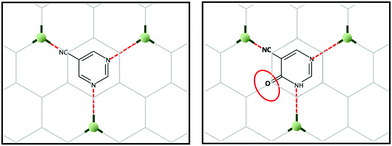
Taking into account the above, we set our minds to designing a novel 2D-MOF with a potentially large number of applications. For this, and inspired by multilayer graphene, we generated graphene-like layers as a template, promoting coordination links at 120 degree angles. To generate some asymmetry in the network, we could have used pyrimidine-5-carbonitrile as the ligand; however, we decided to use 4-hydroxypyrimidine-5-carbonitrile as this linker possesses an oxygen atom in the para position, which can be an excellent alternative to increase the extended aromaticity and introduce electronic density in the channels of the possible MOF (Scheme 1).
Finally, we had to choose the ideal metal ion. In this case, we decided to use copper(II) because of its easy plasticity of its coordination sphere, which would allow it to display a trigonal bipyramid geometry. Moreover, another possibility could be that within the solvothermal reaction, Cu(II) could be reduced to Cu(I) with a flat trigonal geometry, as it would have to maintain the desired graphene type network. The choice of copper as the metal ion is the perfect choice that would favour the formation of the desired two-dimensional network, thereby achieving graphene-like networks. The copper-ligand linkage, moreover, enables π–d conjugation in a 2D plane.
As a result, we present in this work a novel MOF based on 2D-coordination polymers (CPs) with the formula [Cu(4hypymca)]n (hereafter compound 1) that shows a distorted honeycomb-like structure and shares some features with graphene. Moreover, we report on its structural and electronic properties under pressure and upon doping, both promising strategies to improve material conductivity.
When we carried out the reaction between the above ligand and copper chloride, we obtained a bidimensional CP that crystallizes in the orthorhombic system, in the Pbcm space group. The geometry around copper(I) may be described as a distorted trigonal planar environment that involves the N atoms pertaining to three independent 4hypymca linkers (Fig. 1). These three nitrogen atoms correspond to two nitrogen atoms from the pyrimidine rings of 4hypymca and one nitrogen pertaining to the cyanide group. The Cu–Npyr bond distances are 1.935(5) and 1.955(5) Å, while the Cu–Ncyano distance has a value of 2.009(6) Å. These distances lie within the expected range.14
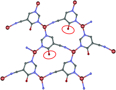 | ||
| Fig. 1 Perspective of coordination mode of 4hypymca and the distorted trigonal environment of the copper ions. | ||
A perfectly planar hcb network is formed from tiled neutral Cu3(4hypymca)3 units running parallel to the ab plane (Fig. 2). In these sheets, Cu(I) ions exhibit a CuN3 coordination polyhedron with a distorted trigonal geometry. The equatorial positions are occupied by three nitrogen atoms belonging to three different bridging ligands, which adopt a planar conformation. Each layer is therefore neutral, as is the case for graphene, and can be conceived as a self-standing monolayer material.
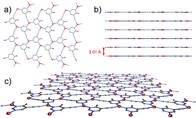 | ||
| Fig. 2 (a) View of the 2D plane in the MOF. (b) Separation among sheets in the MOF. (c) Perspective view of a 2D-layer of the MOF. | ||
Compound 1 exhibits unsupported cuprophilic interactions among layers (Fig. S1, ESI†), featuring infinite (Cu⋯Cu)n chains spanning the crystal lattice with identical intermolecular Cu⋯Cu distances (3.0160(9) Å), which are close to the separation found in paddle-wheel shaped dimeric entities or 1D CPs.15 Nonetheless, a search for structures deposited in the CSD database with similar arrangements did not yield any results. Instead, the linkers are, from one layer to the next, staggered in the c direction. Thus, we can describe the complete structure as a 2D-dimensional network formed by metal–organic layers, joined by weak Cu⋯Cu metal interactions along the c axis.
Subsequently, the material was also subjected to high pressure diffraction measurements so as to study the potential flexibility of the 3D packing. To this end, we have managed to apply 0.9, 2.75 and 4.2 GPa to the sample and we have measured the crystalline structure using XRD (structure 2 = 4.2 GPa). In general, the layers of this compound under pressure preserve the original topology, without distortion of the flat arrangement, although the interlayer distance is observed to be reduced from 3.01 to 2.78 Å (Fig. 3). Further details of bond lengths and angles are reported in Table S2 (ESI†). This, in turn, causes a radical change in the colour of the crystal from yellow to red, as previously reported for other Cu-based systems.16 We also found that the linear (Cu⋯Cu)n chains are not completely straight anymore in 2, a fact that is not surprising in view of observations for other metallic chains.17
In order to get a deeper insight into the physical properties of the layered structure, we decided to perform theoretical (DFT) calculations on a Cu3L63− unit. The π electronic density is obtained by means of the Electron Localization Function (ELF) calculated using the Multiwfn suite of programs,18 see Fig. S6 (ESI†), indicating a highly extended π electronic structure on each sheet. This insight can be further extended by performing band structure calculations as implemented in the OpenMX code.19 We employed the PBE functional20 and a triple-zeta basis set for all atoms. Fig. 4 shows the band structure obtained for the original compound (panel a) and the one obtained upon compression (panel b) along selected paths in the orthorhombic cell of the reciprocal space (see inset c for a representation of the Brillouin zone). The curvature of an energy band is known to be related to the effective mass, which in turn determines the mobility inside a crystal. The final conductivity obviously depends on the position of the chemical potential. This is determined by the type of free carriers generated upon doping the material. However, analysing the shape of a band can provide important information on how good the conductivity in that specific band can be, once it becomes energetically accessible to carriers. In the case of both structures shown in Fig. 4, conductivity seems to be possible in the conduction band and especially along the GZ and GX directions. This is suggested by the parabolic (free-electron like) behaviour of the band shape observed along these two directions. The same applies to the GY direction, albeit not to the same extent.
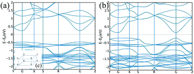 | ||
| Fig. 4 Band structure for the original compound (a) and compressed structure (b). The inset (c) contains a representation of the Brillouin zone. | ||
Overall, the band structure of the original and compressed materials differs in the value of the band gap (which is narrower in the compressed compound by 0.35 eV at the G point) and in the shape of the valence band. The latter is rather flat in the initial structure, indicating a heavy effective mass and poor conduction, whereas this is not the case for the compressed compound in the GZ and GR directions, implying that a sizable conductivity seems to be possible in the valence band as well in this case. Further details on the density of states can be found in the ESI.†
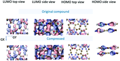
In Fig. 5, the spatial distribution of the wavefunction for both structures is shown at the G point for the lowest unoccupied (conduction band) and highest occupied (valence band) states (henceforth called the LUMO and HOMO, in analogy with the molecular-orbital terminology). In the LUMO top-view representation of both compounds, we observe a higher amount of overlap along the GX direction than along the GY direction, which agrees with the difference in the band curvature observed between these two paths in the conduction band. In addition, the corresponding side view reveals that the conductivity along the z axis can take place either along the Cu–Cu chains normal to the planes or along the overlap formed between the pz orbitals of C (or N) atoms belonging to two different planes (and not necessarily aligned perpendicularly to the plane).
As for the HOMO, the top view shows, overall, a lower degree of overlap with respect to the LUMO (consistent with the flatness observed for the valence band in the GY and GX directions). Nevertheless, the side view reveals that, in the compressed structure 2, the distribution of the wavefunction in the z direction (normal to the planes) seems to be slightly more delocalized across the planes, which could give rise to higher conductive properties. This again agrees well with the different behaviours observed for the valence band around the G point in the compressed compound with respect to the original structure.
To understand the effect on the electronic structure of piling multiple layers as compared to a single layer or two layers, we have analysed the band structure of these two systems (Fig. S7, ESI†). The valence band is found to be rather flat in both cases along all the reciprocal paths, whereas a more free-electron behaviour is observed in the conduction band at the G point for the monolayer (barely visible) and for the bilayer (noticeable), albeit not as much as in the 3D structure.
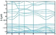
Finally, one must bear in mind that the conductivity will be ultimately determined by the position of the chemical potential, which in turn will be dependent on the kind of free carriers (i.e. kind of doping). In the case of the initial structure of 1 (before compression), doping strategies that could a priori shift the conduction band towards the Fermi level should be adopted. This would allow one to take advantage of the conductive properties of the conduction band discussed above. As an example, in Fig. 6, we show how the band structure of the 3D MOF before compression changes upon replacement of 1![[thin space (1/6-em)]](https://www.rsc.org/images/entities/char_2009.gif) :
:![[thin space (1/6-em)]](https://www.rsc.org/images/entities/char_2009.gif) 4 oxygen with a hydrogen atom. We observe that indeed such a strategy makes the conduction band accessible for charge carriers. Further research would be needed to study how doping may affect the chemical stability of this MOF and, consequently, what would be the right concentration and best type of replacement in order to achieve the highest performance (see the ESI† for further discussion). This goes beyond the scope of the present work and will be pursued in future studies.
4 oxygen with a hydrogen atom. We observe that indeed such a strategy makes the conduction band accessible for charge carriers. Further research would be needed to study how doping may affect the chemical stability of this MOF and, consequently, what would be the right concentration and best type of replacement in order to achieve the highest performance (see the ESI† for further discussion). This goes beyond the scope of the present work and will be pursued in future studies.
In summary, we have described for the first time a 2D-MOF based on copper and 4-hydroxypyrimidine-5-carbonitrile as the linker. High pressure XRD measurements reveal that the interlayer spacing of this material may be changed from 3.01 to 2.78 Å, changing the colour of the crystal and (according to our DFT-based results) varying the conductive properties of the material. We have analysed the band structure, which indicates that this material shows different conduction properties depending on whether pressure is applied or not. In the case of compound 1, the band structure indicates that this material is conductive in the conduction band, along the direction perpendicular to the sheets and within the sheet plane. However, the gap becomes narrower in the compressed structure 2 and the material becomes conductive also in the valence band along the z direction. On analysing the 3D structure, we concluded that n-type doping could be a good strategy to improve the conductivity of this material. These results pave the way for the development of novel layered materials, which can be deposited as single layers or engineered into a 3D structure to obtain efficient materials with specific properties for pressure sensing. Further studies in these directions are currently being carried out in our laboratory, focusing, for instance, on the possible employment of different types of similar ligands.
This work has been supported by the European Union (Grant Agreement No. 604391 Graphene Flagship), the Swiss National Science Foundation (200020_162861), the Spanish MICINN (CEX2018-000805-M and projects CTQ2015-69163-CO2-R1, PGC2018-102052-B-C21, PGC2018-102052-A-C22, PGC2018-102047-B-I00, FIS2016-80434-P and PID2019-109539GB-C43), Junta de Andalucía (FQM-394), and Comunidad Autónoma de Madrid through the Nanomag COST-CM Program (No. S2018/NMT-4321). J. J. P. thanks the Fundación Ramón Areces (XVIII Concurso Nacional para la Adjudicación de Ayudas a la Investigación en Ciencias de la Vida y de la Materia, 2016). LAZ acknowledges financial support from University of Seville through the VI PPIT-US program. W. P. was funded by the CNPq Fellowship Programme (Pós-doutorado júnior) under Grant No. 405107/2017-0. J. J. P. acknowledges the computer resources and assistance provided by the Centro de Computación Científica of the Universidad Autónoma de Madrid and the computer resources at MareNostrum and the technical support provided by Barcelona Supercomputing Center (FI-2019-2-0007). Finally, we also thank the CSIRC-ALHAMBRA computing centre.
Conflicts of interest
There are no conflicts to declare.Notes and references
- P. Dechambenoit and J. R. Long, Chem. Soc. Rev., 2011, 40, 3249–3265 RSC.
- T. Dietl and H. Ohno, Rev. Mod. Phys., 2014, 86, 187–251 CrossRef CAS.
- S.-N. Zhao, Y. Zhang, S.-Y. Song and H. J. Zhang, Coord. Chem. Rev., 2019, 398, 113007 CrossRef CAS.
- H. Furukawa, K. E. Cordova, M. O'Keeffe and O. M. Yaghi, Science, 2013, 341, 974 CrossRef CAS PubMed.
- B. Li, M. Chrzanowski, Y. Zhang and S. Ma, Coord. Chem. Rev., 2016, 307, 106–129 CrossRef CAS.
- J. Cepeda, E. San Sebastian, D. Padro, A. Rodríguez-Diéguez, J. A. García, J. M. Ugalde and J. M. Seco, Chem. Commun., 2016, 52, 8671–8674 RSC.
- (a) J. M. Seco, D. Fairen-Jimenez, A. J. Calahorro, L. Méndez-Liñán, M. Pérez-Mendoza, N. Casati, E. Colacio and A. Rodríguez-Diéguez, Chem. Commun., 2013, 49, 11329–11331 RSC; (b) J. Cepeda, M. Perez-Mendoza, A. J. Calahorro, N. Casati, J. M. Seco, M. Aragones-Anglada, P. Z. Moghadam, D. Fairen-Jimenez and A. Rodrıguez-Dieguez, J. Mater. Chem. A, 2018, 6, 17409–17416 RSC.
- J. Cepeda and A. Rodríguez-Diéguez, CrystEngComm, 2016, 18, 8556–8573 RSC.
- A. J. Calahorro, I. Oyarzabal, B. Fernández, J. M. Seco, T. Tian, D. Fairen-Jimenez, E. Colacio and A. Rodríguez-Diéguez, Dalton Trans., 2016, 45, 591–598 RSC.
- D. Briones, B. Fernández, A. J. Calahorro, D. Fairen-Jimenez, R. Sanz, F. Martínez, G. Orcajo, E. San Sebastián, J. M. Seco, C. Sánchez González, J. Llopis and A. Rodríguez-Diéguez, Cryst. Growth Des., 2016, 16, 537–540 CrossRef CAS.
- B. Fernández, I. Fernández, J. Cepeda, M. Medina-O’Donnell, E. E. Rufino-Palomares, A. Raya-Barón, S. Gómez-Ruiz, A. Pérez-Jiménez, J. Antonio Lupiáñez, F. J. Reyes-Zurita and A. Rodríguez-Diéguez, Cryst. Growth Des, 2018, 18, 969–978 CrossRef.
- J. M. Seco, E. San Sebastián, J. Cepeda, B. Biel, A. Salinas-Castillo, B. Fernández, D. P. Morales, M. Bobinger, S. Gómez-Ruiz, F. C. Loghin, A. Rivadeneyra and A. Rodríguez-Diéguez, Sci. Rep., 2018, 8, 14414–14423 CrossRef PubMed.
- R. Dong, Z. Zhang, D. C. Tranca, S. Zhou, M. Wang, P. Adler, Z. Liao, F. Liu, Y. Sun, W. Shi, Z. Zhang, E. Zschech, S. C. B. Mannsfeld, C. Felser and X. Feng, Nat. Commun., 2018, 9, 2637, DOI:10.1038/s41467-018-05141-4.
- J. Troyano, E. Zapata, J. Perles, P. Amo-Ochoa, V. Fernández-Moreira, J. I. Martínez, F. Zamora and S. Delgado, Inorg. Chem., 2019, 58, 3290–3301 CrossRef CAS PubMed.
- M. Köberl, M. Cokoja, W. A. Herrmann and F. E. Kühn, Dalton Trans., 2011, 40, 6384–6859 Search PubMed.
- Q. Benito, B. Baptiste, A. Polian, L. Delbes, L. Martinelli, T. Gacoin, J.-P. Boilot and S. Perruchas, Inorg. Chem., 2015, 54, 9821–9825 CrossRef CAS PubMed.
- S. You, Z. Li, L. Yang, C. Dong, L. Chen, C. Jin, J. Hu, G. Shen and H. Mao, J. Solid State Chem., 2009, 182, 3085–3090 CrossRef CAS.
- T. Lu and F. Chen, J. Comput. Chem., 2012, 33, 580–592 CrossRef CAS PubMed.
- T. Ozaki, K. Nishio and H. Kino, Phys. Rev. B: Condens. Matter Mater. Phys., 2010, 81, 035116 CrossRef.
- J. P. Perdew, K. Burke and M. Ernzerhof, Phys. Rev. Lett., 1997, 78, 1396 CrossRef CAS.
Footnote |
| † Electronic supplementary information (ESI) available: General methods and materials, Crystallographic tables and figures. CCDC 1944930 and 1993341–1993343. For ESI and crystallographic data in CIF or other electronic format see DOI: 10.1039/d0cc03564e |
| This journal is © The Royal Society of Chemistry 2020 |

