
A “chain–lock” strategy to construct a conjugated copolymer network for supercapacitor applications†
Weishuo
Li‡
a,
Yitong
Guo‡
a,
Yilin
Wang‡
a,
Xing
Xing
b,
Xiaolong
Chen
a,
Jiaoyi
Ning
a,
Hongtao
Yu
a,
Yuhao
Shi
a,
Imran
Murtaza
c and
Hong
Meng
 *a
*a
aSchool of Advanced Materials, Peking University Shenzhen Graduate School, Shenzhen 518055, China. E-mail: menghong@pkusz.edu.cn
bResearch & Development Institute of Northwestern Polytechnical University, (Shenzhen), Northwestern Polytechnical University, Shenzhen, 518057, China
cDepartment of Physics, International Islamic University, Islamabad 44000, Pakistan
First published on 27th November 2018
Abstract
A “chain–lock” strategy was used to build a conjugated polymer network by a facile electrochemical copolymerization method. A classical donor–acceptor monomer, 4,7-bis(2,3-dihydrothieno[3,4-b][1,4]dioxin-5-yl)benzo[c][1,2,5] thiadiazole (DEBT), was selected as the “chain” and a three-branch monomer, tris(4-(2,3-dihydrothieno[3,4-b][1,4]dioxin-5-yl)phenyl) amine (TETPA), as the “lock”. The copolymer shows a hierarchical porous structure, considerable capacitance and excellent stability. This probably contributes to the good electrical conductivity of the π-conjugated skeleton, improved ionic conductivity and structural stability of the porous network. This “chain–lock” polymer with various monomer selections and adjustable molecular structure shows great promise in the energy storage field. This strategy also provides a universal solution for conjugated porous polymer design, which has promising applications in many fields.
1. Introduction
Conducting polymers (CPs) have been studied as energy storage materials for several decades, and have shown particularly great advantages and promise in recent years as emerging flexible electronics.1–3 Traditional conducting polymers (e.g. polyaniline and polypyrrole) have very high theoretical capacitances.4 However, the practical capacitances of the polymers are usually lower than their theoretical values, and at the same time many polymers suffer from poor cycling stability which greatly hampers their practical application.5 However, this still provides a bright possibility for overcoming the bottleneck of the low energy density of supercapacitor devices.6 Conducting polymers store energy through fast redox reactions; in this process electrolyte ions diffuse and dope into the polymer to accomplish the reactions. This doping/de-doping process usually causes a considerable volume change in the electrode material and leads to a decrease in electrochemical performance.7 Moreover, much of the inner material has not been fully utilized because of hindered counter-anion diffusion and low conductivity, which is one important reason for the practical capacitance of the polymer usually being lower than its theoretical capacitance.6 To solve these problems, researchers are trying out strategies such as preparing composites by combining CPs with other materials, including carbonaceous materials and MOFs.8–10 This mix-up strategy has proved to be effective and a synergy effect is observed with elaborate control. Apart from the composite strategy, it is also interesting to design and tune the intrinsic structure of a polymer electrode without introducing other materials, which can simplify the electrode preparation process and obtain better integrity.11 Similar to electric double layer capacitors, an appropriate porous electrode structure is also favored in pseudocapacitive materials, which helps in the diffusion of electrolyte ions and structure maintenance during cyclic charge/discharge.5 In recent years there have been reports on novel types of porous pseudocapacitive materials, including covalent organic frameworks (COFs),12 conjugated microporous polymers (CMPs)13–15 and other polymer networks.16,17 However, many of these materials suffer from intricate synthesis processes and low conductivity or stability.Herein, we explore a “chain–lock” strategy to construct a porous copolymer for use as a supercapacitor electrode, in which a classical donor–acceptor unit, 4,7-bis(2,3-dihydrothieno[3,4-b][1,4]dioxin-5-yl)benzo[c][1,2,5]thiadiazole (DEBT), was selected as the “chain” and a three-branch unit, tris(4-(2,3-dihydrothieno[3,4-b][1,4]dioxin-5-yl)phenyl)amine (TETPA), was selected as the “lock”. Such a combination is selected based on the consideration that “chain” units can make the copolymer P(DEBT/TETPA) more conductive for carrier transport, while the “lock”, having a pyramidal structure, helps to construct a dendritic porous structure. Due to the sp3 hybrid orbital of N in TETPA, the remaining lone pair of electrons occupies the fourth tetrahedral position producing a nonplanar structure, leading to the porous structure of the P(DEBT/TETPA) copolymer electrode. D–A polymers have been demonstrated as promising energy storage materials because of their tunable molecular structures and unique ambipolar doping properties.18 However, few D–A polymers have been reported to be applied in supercapacitors, because they suffer from low capacitance and unsatisfactory stability.19–23 In this manuscript, an electrochemical copolymerization method was used to construct porous polymer electrodes by introducing “locks” into D–A polymer chains. The “chain” and “lock” monomers are covalently combined and their ratios can be adjusted to obtain an ideal network structure copolymer. The experimental results show that adding a small amount of branches during the electropolymerization as “locks”, helps in constructing a polymer network with good electrochemical performance. This copolymer, P(DEBT/TETPA), has a π-conjugated conductive skeleton and also a hierarchical porous structure. Compared with the PDEBT homopolymer, the copolymer shows significantly improved capacitance, wide potential range and excellent stability in the p-doped state, and is an ideal supercapacitor electrode material. Besides, it also inherits the ambipolar doping ability of the original D–A polymer. This design and synthesis of hierarchical conjugated polymer networks provides a universal strategy for new material design, which is promisingly applied in various fields including energy storage, catalysis, gas adsorption and so on.24
2. Experimental section
2.1 Materials and synthesis
The synthetic steps of the monomers are provided in the ESI.† All chemicals were used as received without further purification. Dichloromethane (DCM) and acetonitrile (ACN) were pre-dried over activated 4A molecular sieves and refluxed over calcium hydride for 2 h before distillation. Tetra-n-butylammonium hexafluorophosphate (TBAPF6) was purchased from J&K Chemicals. Anhydrous propylene carbonate (PC) of 99.7% purity was used as received from Sigma-Aldrich.2.2 Electrochemical synthesis and characterization of P(DEBT/TETPA)
Solutions of different monomer ratios were prepared, maintaining a total concentration of 5 mM and a series of chain–lock monomer mole ratios were used from 20![[thin space (1/6-em)]](https://www.rsc.org/images/entities/char_2009.gif) :1 to 1:1. Both monomers at designated concentrations were completely dissolved together in dichloromethane ultrasonically. And then electrochemical polymerization was carried out in a three-electrode system with a platinum disk electrode (diameter 2 mm) as the working electrode, a Pt wire as the counter electrode and a Ag/Ag+ electrode (Ag wire in 0.01 M AgNO3/0.1 M TBAPF6/ACN) as the reference electrode. The electrolyte was a 0.1 M TBAPF6/DCM solution containing both monomers. Electropolymerization of DEBT or TETPA individually was also carried out at a monomer concentration of 5 mM. The electropolymerization process was carried out using the CV method by cycling between −0.8 and 1.0 V for 10 cycles at a scan rate of 100 mV s−1. All electrochemical experiments were carried out using a Gamry Interface 1000 electrochemical workstation. The mass of the electrodeposited polymer was monitored using a eQCM CHI400C from Shanghai Chenhua Corporation. All electrochemical characterization processes of single electrodes (cyclic voltammetry, galvanostatic charge–discharge and electrochemical impedance spectrometry) were performed in a three-electrode cell containing a 0.1 M TBAPF6/ACN electrolyte solution. EIS was performed in the frequency range from 100 kHz to 1 Hz at open circuit potential by applying a small potential of 10 mV sinusoidal signal. Stability tests were performed in a water-free and oxygen-free three-electrode cell containing a 0.1 M TBAPF6/PC electrolyte by bubbling nitrogen for 15 min before the experiment. The copolymer material was deposited on ITO glass and washed with DCM to remove excess monomer and electrolyte. Then the copolymer film on ITO glass was imaged by a scanning electron microscope (SEM) (ZEISS SUPRA 55, Germany). X-ray Photoelectron Spectroscopy (XPS) measurements were carried out using an ESCALAB 250Xi X-ray Photoelectron Spectrometer. The material was also collected from ITO, ultrasonically dispersed in ethanol and added dropwise on a carbon support film for TEM characterization (JEM 3200FS, JEOL).
:1 to 1:1. Both monomers at designated concentrations were completely dissolved together in dichloromethane ultrasonically. And then electrochemical polymerization was carried out in a three-electrode system with a platinum disk electrode (diameter 2 mm) as the working electrode, a Pt wire as the counter electrode and a Ag/Ag+ electrode (Ag wire in 0.01 M AgNO3/0.1 M TBAPF6/ACN) as the reference electrode. The electrolyte was a 0.1 M TBAPF6/DCM solution containing both monomers. Electropolymerization of DEBT or TETPA individually was also carried out at a monomer concentration of 5 mM. The electropolymerization process was carried out using the CV method by cycling between −0.8 and 1.0 V for 10 cycles at a scan rate of 100 mV s−1. All electrochemical experiments were carried out using a Gamry Interface 1000 electrochemical workstation. The mass of the electrodeposited polymer was monitored using a eQCM CHI400C from Shanghai Chenhua Corporation. All electrochemical characterization processes of single electrodes (cyclic voltammetry, galvanostatic charge–discharge and electrochemical impedance spectrometry) were performed in a three-electrode cell containing a 0.1 M TBAPF6/ACN electrolyte solution. EIS was performed in the frequency range from 100 kHz to 1 Hz at open circuit potential by applying a small potential of 10 mV sinusoidal signal. Stability tests were performed in a water-free and oxygen-free three-electrode cell containing a 0.1 M TBAPF6/PC electrolyte by bubbling nitrogen for 15 min before the experiment. The copolymer material was deposited on ITO glass and washed with DCM to remove excess monomer and electrolyte. Then the copolymer film on ITO glass was imaged by a scanning electron microscope (SEM) (ZEISS SUPRA 55, Germany). X-ray Photoelectron Spectroscopy (XPS) measurements were carried out using an ESCALAB 250Xi X-ray Photoelectron Spectrometer. The material was also collected from ITO, ultrasonically dispersed in ethanol and added dropwise on a carbon support film for TEM characterization (JEM 3200FS, JEOL).
3. Results and discussion
3.1 Electrochemical synthesis of P(DEBT/TETPA)
In this “chain–lock” strategy, “chain” and “lock” monomers were carefully selected and covalently bonded by an electrochemical copolymerization method. A classical linear D–A–D monomer, DEBT, was selected as the “chain” unit to construct a π-conjugated conductive skeleton. And a three-branch centrosymmetric monomer, TETPA, was added to help construct a porous polymer network and enhance the ionic conductivity. Chemical synthetic routes of the “chain” and “lock” monomer are provided in the ESI.† The central nitrogen in TETPA is redox active and contributes to the pseudocapacitance in the whole conjugated organic framework. The 3,4-ethylenedioxythiophene (EDOT) units connected terminally help to lower the electropolymerization potential of the lock monomer. Such a combination of “chain” and “lock” blocks helps in the construction of a conjugated porous polymer network (see Fig. 1). The oxidation potential of the monomers was investigated by the first cycle of their electrochemical polymerization curves. According to Fig. 2a, the oxidation and polymerization of DEBT start at about 0.6 V. The oxidation peak of TETPA at 0.4 V is attributed to the oxidation of nitrogen as no polymer deposition was observed at this potential. And the onset of polymerization of TETPA was estimated to be at 0.7 V, similar to that of DEBT. This condition is important for guaranteeing the formation of bicomponent copolymer rather than only one single polymer. The mixed solution shows an oxidation onset of 0.9 V and the electropolymerization curve is shown in Fig. 2b, with a gradual increase in current density after each cycle, indicating the increasing amount of polymer on the working electrode. Through this electrochemical copolymerization method, a dark green porous polymer material was obtained.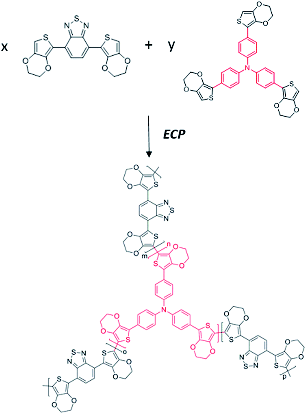 | ||
| Fig. 1 Synthetic route to P(DEBT/TETPA). | ||
 | ||
| Fig. 2 (a) The 1st CV cycle of DEBT, TETPA and their mixed solution; (b) electropolymerization curve of the DEBT/TETPA mixed solution. | ||
By this “chain–lock” strategy, the π-conjugated conductive skeleton contributes to pseudocapacitive charge storage, while the space between molecular chains can provide channels for electrolyte ions, forming an ideal energy storage electrode.
3.2 Optimization of the chain–lock ratio
To obtain a copolymer with an ideal porous structure and satisfactory energy storage performance, the ratio of the “chain” and “lock” monomers was optimized. Experiments with a series of monomer ratios were performed, by keeping the total concentration at 5 mM and adjusting the chain–lock mole ratios from 1:0 to 0:1. The CV curves of the polymers (Fig. 3a) show that the homo-polymer PDEBT (ratio of 1:0 without TETPA) has a wide potential range of 1.4 V but relatively low current. With a small addition of the three-branch monomer TETPA, the copolymer shows a slightly narrowed potential range but obviously elevated peak current. At a monomer ratio of 9:1 (CV shown as the red curve in Fig. 3a), the CV curve achieves the largest integration in the potential range of −0.8 V to 0.8 V, indicating that the copolymer achieves the highest capacitance. Several oxidation peaks appear in the p-doping process, at −0.3 V, 0 V and 0.35 V, respectively. The oxidation peak at −0.3 V is from DEBT, while the peak at 0.35 V is from both DEBT and TETPA. The peak at 0 V is attributed to the DEBT and TETPA in the copolymer. The reduction–oxidation peaks are not very sharp and a high current density can be maintained in a wide potential range (from −0.2 V to 0.8 V), which greatly contributes to a steady charge–discharge process and large average capacitance. As E = 1/2CV2, the areal energy densities of the polymer electrodes in their own optimal potential windows were also calculated (see Table 1). Copolymer 3 with the highest capacitance (C) and quite wide potential window (V) achieves the largest energy density, showing a great improvement compared with PDEBT (polymer 1). The capacitance of PTETPA (polymer 7) is almost as high as that of copolymer 3, showing its good pseudocapacitive ability, while its potential window is narrow. Therefore, the energy density of PTETPA is much lower than that of the optimized copolymer. Besides, the morphology of the copolymer electrode is affected by the ratio of the monomers in the electrolyte for electropolymerization as shown in Fig. S1.† When the monomer mole ratio (DEBT:TETPA) is 9:1, a more porous electrode is obtained than when the ratios are 3:1 and 1:1, which corresponds to the excellent supercapacitive performance of copolymer 3 when the ratio is 9:1. Moreover, the electrochemical environment of electropolymerization plays a role as well. As shown in Fig. S1,† on comparing (a) and (d), when DCM is used as the electrolyte solvent for electropolymerization, the film is highly porous which is favorable for the supercapacitor. When BFEE/THF is used, dense particles appear in the electrode, which exposes much less active surface than the electrode deposited in DCM.
 | ||
| Fig. 3 (a) CV curve of copolymers with different monomer ratios (DEBT:TETPA); (b) CV curve showing ambipolar doping of the copolymer at a monomer ratio 9:1. | ||
| Polymer | Monomer mole ratio (DEBT:TETPA) |
Capacitance (mF cm−2) | Potential window (V) | E (mW h cm−2) |
|---|---|---|---|---|
| 1 | 1:0 |
42 | 1.4 | 0.0114 |
| 2 | 18:1 |
44 | 1.4 | 0.0119 |
| 3 | 9:1 |
76 | 1.3 | 0.0178 |
| 4 | 3:1 |
54 | 1.1 | 0.0092 |
| 5 | 1.5:1 |
65 | 0.9 | 0.0072 |
| 6 | 1:1 |
65 | 0.8 | 0.0058 |
| 7 | 0:1 |
74 | 0.7 | 0.0050 |
The specific capacitance of copolymer 3 and PDEBT was measured using a quartz crystal microbalance, which turns out to be 149 F g−1 and 104 F g−1, respectively (measured by CV at 10 mV s−1). This significant improvement may be attributed to the construction of a network structure copolymer, which is provided with a hierarchical porous structure for the more effective diffusion of electrolyte ions into the pseudocapacitive electrode material. A porous structure for ion penetration and good conductivity for carrier transport are both essential for the performance of pseudocapacitors. TETPA which has a pyramid structure can contribute to the porous structure of the copolymer, while DEBT can contribute to the carrier conductivity of the copolymers. A suitable combination and ratio lead to the best performance of the supercapacitor. In this work, when the DEBT/TETPA monomer ratio is 9:1 in the electrolyte, the electropolymerized electrode will give the highest capacitance.
XPS experiments were performed to check the ratio of the two monomers as shown in Fig. S2.† The different compositions can be checked through N 1s spectra, because the chemical environment for N is different in DEBT and TETPA. The actual ratio of the chain to lock in the copolymer P(DEBT/TETPA) can be roughly obtained by integrating the area of the peaks. When the monomer mole ratio (DEBT:TETPA) is 1:1 in the electrolyte, the XPS signal is very weak, which is due to the very low conductivity of the film, meaning that DEBT can seldom be electropolymerized into the copolymer. When the monomer mole ratio (DEBT:TETPA) is 3:1 in the electrolyte, the actual ratio of the copolymer is quite low, only 1.47:1. When the monomer mole ratio (DEBT:TETPA) increases to 9:1 in the electrolyte, the actual ratio I copolymer is a bit higher, at 1.89:1. On comparing the two monomers in the electrolyte, a much lower percentage of DEBT than TETPA can be electropolymerized, probably ascribing to their different monomer functionalities and reaction rates with similar onsets of potential for electropolymerization. Moreover, with determined composition, the porous structure of P(DEBT/TETPA) copolymer electrode could be constructed owing to the sp3 hybrid orbital of N in TETPA, which makes the remaining lone pair of electrons occupies the fourth tetrahedral position producing a pyramidal structure.
There should also be some contribution from the electric double layer capacitance as well as the pseudocapacitance of nitrogen in TETPA. The BET test for surface area measurement was carried out in this experiment. Due to the very little amount of electropolymerization product, we could not get a solid signal. And the different physical or chemical processes in nitrogen adsorption or electrochemical doping may cause a distinct difference in the practical contributing surface area. Compared with the reports of other groups, the specific capacitance value of P(DEBT/TETPA) is slightly lower than that of the polyaminoanthraquinone networks recently reported by Liao (165–576 F g−1).15 But considering the differences in experimental conditions (polymer synthetic method) and evaluation of capacitance (potential windows), it's hard to directly compare the capacitance values. The comparison of the capacitance value of P(DEBT/TETPA) with that in the literature reported recently is in Table S1.†
The electrochemical copolymerization method selected in this work is rather simple and can be applicable for various monomers. Besides, the copolymer retains a particularly wide potential window the same as the initial D–A–D polymer. The copolymer P(DEBT/TETPA) is also confirmed to have both p- and n-doping properties (see Fig. 3b). A pair of quasi-reversible reduction peaks appears in the negative potential region, though the n-doping capacitance is lower than the p-doping one and mostly decayed after 100 cycles (see Fig. S3†). This ambipolar property may be further improved by tuning the chain–lock molecular structures and under more strict water-free and oxygen-free conditions.
3.3 P(DEBT/TETPA) as a supercapacitor electrode material
As it is a promising energy storage material, the electrochemical performance of the copolymer P(DEBT/TETPA) was characterized by cyclic voltammetry (CV), galvanostatic charge–discharge (GCD) and electrochemical impedance spectroscopy (EIS). The GCD curves in Fig. 4a show that the copolymer film can be charged and discharged very steadily in a quite wide potential range of 1.0 V, even at a high current density of 50 mA cm−2. | ||
| Fig. 4 (a) Galvanostatic charge–discharge (GCD) curves of P(DEBT/TETPA) on the Pt disk electrode (chain–lock ratio of 9:1); (b) areal capacitance of the copolymer electrode at different current densities (calculated from GCD); (c) electrochemical impedance spectrometry of the copolymer and PDEBT measured in a three-electrode system; (d) cycling stability of the copolymer measured by the CV method (inset: CV curves of the copolymer before and after 2000 cycles). | ||
The areal capacitance of the single electrode was calculated to be 151.2 mF cm−2 (at current density of 1 mA cm−2), which is more than twice that of PDEBT (65 mF cm−2). The areal capacitance at different current densities (from 1 mA cm−2 to 50 mA cm−2) changes a little, indicating the good rate capability of the polymer electrode (see Fig. 4b).
EIS was also carried out to study the electrochemical process in the electrode. Judging from the horizontal axis intercept in the EIS plot, the copolymer electrode has a slightly larger internal resistance (167 Ω) than PDEBT (155 Ω) (see Fig. 4c). This is because electron transfer between the chains of the network copolymer is a little more difficult due to spatial hindrance. This 10% percent increase in resistance is regarded as acceptable and will not significantly influence the electrochemical performance of the polymer electrode. The Nyquist plot of PDEBT exhibits a straight line in the low frequency range with a negligible arc in the high-frequency range, resulting from its very fast double-layer charge transfer at the electrode–electrolyte interface.25 And the Nyquist plot of the copolymer shows a semicircle in the high frequency range followed by an ∼90° straight line from the real part axis, attributed to the fast surface-controlled faradaic process. Interestingly, in the low frequency region a larger deviation of the copolymer away from the Y-axis was observed as compared to PDEBT. This could be attributed to the lower diffusion contribution by the pores of the copolymer electrode. For a more compact PDEBT electrode, the diffusion inside the solution-phase becomes a limiting kinetic factor resulting in an increase in the impedance. By increasing the porosity with our strategy, the pores of the copolymer electrode are filled with the electrolyte and solution-phase diffusion is facilitated resulting in a decrease in the impedance.
Moreover, a symmetric supercapacitor with two P(DEBT/TETPA) electrodes was fabricated and characterized as shown in Fig. S4.† There might be some potential room for improvement as the nonideal conditions in the devices, including the overall series resistance arising from imperfect electric contacts.20 Meanwhile, the separate paper and gel electrolyte could also hinder the ions transportation to some degree. Its performance can be improved by choosing a more advanced and proper device fabrication, which we will work on in the future.
Besides, stability is another important factor for conducting polymer electrode materials, whose poor cycling stability often becomes a serious drawback in practical applications. No decrease in the capacitance of the copolymer was found in a 2000 cycle CV test (see Fig. 4d). Instead, a slight increase (4%) in average capacitance was observed which may be due to polymer packing morphology changes during cycling, which leads to the shape change of the CV curves (see Fig. 4d inset).23 For comparison, the cycling stability of PDEBT is also tested, which shows a 92% retention after 2000 cycles as shown in Fig. S5.† The excellent stability of the network copolymer as an electrode material is crucial for its real application, which provides a very bright future for industrial use.
3.4 Hierarchical porous structure of the copolymer
The morphology and porous structure of the electropolymerized copolymer was characterized by scanning electron microscopy (SEM) and transmission electron microscopy (TEM). From the SEM images of the P(DEBT/TETPA) film on ITO (see Fig. 5a, and b), a porous network structure material made of nanoparticles can be observed. In comparison, the homo-polymer PDEBT shows a smooth surface composed of nanosheets (see Fig. 5c, and d). The porous network structure of the copolymer provides channels for electrolyte counter-ions in the doping/dedoping process. This can greatly contribute to the increase in practical capacitance, as more internal materials can be utilized. Moreover, the porous structure helps to buffer volume changes in the charge/discharge process so that the cycling stability is improved. In the HR-TEM images of P(DEBT/TETPA), the internal microporous structure can be observed (see Fig. 5f). These pores below 2 nm may arise from the space between molecular chains, and also contribute to the electric double layer capacitance due to the increased contact surface area between the electrode and electrolyte. | ||
| Fig. 5 (a, and b) SEM images of P(DEBT/TETPA); (c, and d) SEM images of PDEBT; (e, and f) TEM images of P(DEBT/TETPA). | ||
Elemental mapping with TEM was carried out (see Fig. S6†). The SEM and TEM images both confirmed the hierarchical porous structure in the electropolymerized copolymer, from micropores to macropores. This hierarchical conjugated organic framework was demonstrated to have many advantages in energy storage applications, which is proved by its excellent performance in capacitance applications.
4. Conclusions
In summary, an electrochemical copolymerization strategy was successfully used to construct a conjugated polymer network, by combining a traditional donor–acceptor unit, DEBT, as the “chain” and a triphenylamine-based three-branch unit, TETPA, as the “lock”. Our work shows that with only 10% of the “lock” unit, the formation of a porous network during electropolymerization can be significantly assisted. Hierarchical pores formed in the conjugated copolymer, from micropores to macropores, which provide sufficient channels for electrolyte counter-ion diffusion. Such a hierarchical porous structure enhances the utilization of the electrode material and structure maintenance during cycling charge/discharge. The copolymer P(DEBT/TETPA) shows a considerable capacitance of 149 F g−1 and a wide potential range of 1.3 V, as well as excellent cycling stability.This work provides a brand new way of constructing a porous conjugated polymer using a “chain–lock” molecular design strategy. And the copolymer shows ambipolar doping ability and particularly good performance in the p-doped state. Besides, it is useful to introduce more electron withdrawing units into the molecule for the future development of n-doped materials.26,27 Moreover, the hierarchical porous structure and good electric conductivity enables the application of such “chain–lock” copolymers in various fields, such as gas adsorption, heterogeneous catalysis and light emission, in the future.24
Conflicts of interest
There are no conflicts to declare.Acknowledgements
This work was financially supported by the International Cooperation Project (No. 51761145101), Shenzhen Key Laboratory of Organic Optoelectromagnetic Functional Materials of Shenzhen Science and Technology Plan (ZDSYS20140509094114164), Shenzhen Peacock Program (KQTD2014062714543296), National Basic Research Program of China (973 Program, No. 2015CB856505) and Shenzhen Special Funds for Maker (GRCK2017042414370236). We acknowledge Mr Wenguang Zhao's help in the TEM test and Mr JuPeng Cao's help in the SEM test.Notes and references
- C. Cui, W.-Y. Wong and Y. Li, Improvement of open-circuit voltage and photovoltaic properties of 2D-conjugated polymers by alkylthio substitution, Energy Environ. Sci., 2014, 7(7), 2276–2284 RSC.
- T. B. Schon, B. T. McAllister, P. F. Li and D. S. Seferos, The rise of organic electrode materials for energy storage, Chem. Soc. Rev., 2016, 45(22), 6345–6404 RSC.
- B. C. Kim, J. Y. Hong, G. G. Wallace and H. S. Park, Recent Progress in Flexible Electrochemical Capacitors: Electrode Materials, Device Configuration, and Functions, Adv. Energy Mater., 2015, 5(22), 1500959 CrossRef.
- Q. Meng, K. Cai, Y. Chen and L. Chen, Research progress on conducting polymer based supercapacitor electrode materials, Nano Energy, 2017, 36, 268–285 CrossRef CAS.
- G. A. Snook, P. Kao and A. S. Best, Conducting-polymer-based supercapacitor devices and electrodes, J. Power Sources, 2011, 196(1), 1–12 CrossRef CAS.
- P. Simon and Y. Gogotsi, Materials for electrochemical capacitors, Nat. Mater., 2008, 7, 845–854 CrossRef CAS.
- G. Wang, L. Zhang and J. Zhang, A review of electrode materials for electrochemical supercapacitors, Chem. Soc. Rev., 2012, 41(2), 797–828 RSC.
- L. Wang, X. Feng, L. Ren, Q. Piao, J. Zhong, Y. Wang, H. Li, Y. Chen and B. Wang, Flexible Solid-State Supercapacitor Based on a Metal–Organic Framework Interwoven by Electrochemically-Deposited PANI, J. Am. Chem. Soc., 2015, 137(15), 4920–4923 CrossRef CAS PubMed.
- H.-P. Cong, X.-C. Ren, P. Wang and S.-H. Yu, Flexible graphene–polyaniline composite paper for high-performance supercapacitor, Energy Environ. Sci., 2013, 6(4), 1185–1191 RSC.
- T. Liu, L. Finn, M. Yu, H. Wang, T. Zhai, X. Lu, Y. Tong and Y. Li, Polyaniline and polypyrrole pseudocapacitor electrodes with excellent cycling stability, Nano Lett., 2014, 14(5), 2522–2527 CrossRef CAS PubMed.
- Y. Huang, H. Li, Z. Wang, M. Zhu, Z. Pei, Q. Xue, Y. Huang and C. Zhi, Nanostructured Polypyrrole as a flexible electrode material of supercapacitor, Nano Energy, 2016, 22, 422–438 CrossRef CAS.
- C. R. DeBlase, K. E. Silberstein, T. T. Truong, H. D. Abruna and W. R. Dichtel, beta-Ketoenamine-linked covalent organic frameworks capable of pseudocapacitive energy storage, J. Am. Chem. Soc., 2013, 135(45), 16821–16824 CrossRef CAS PubMed.
- H. Zhang, Y. Zhang, C. Gu and Y. Ma, Electropolymerized Conjugated Microporous Poly(zinc-porphyrin) Films as Potential Electrode Materials in Supercapacitors, Adv. Energy Mater., 2015, 5(10), 1402175 CrossRef.
- Y. Kou, Y. Xu, Z. Guo and D. Jiang, Supercapacitive energy storage and electric power supply using an aza-fused pi-conjugated microporous framework, Angew. Chem., Int. Ed., 2011, 50(37), 8753–8757 CrossRef CAS PubMed.
- Y. Liao, H. Wang, M. Zhu and A. Thomas, Efficient Supercapacitor Energy Storage Using Conjugated Microporous Polymer Networks Synthesized from Buchwald-Hartwig Coupling, Adv. Mater., 2018, 30(12), e1705710 CrossRef PubMed.
- M. E. Roberts, D. R. Wheeler, B. B. McKenzie and B. C. Bunker, High specific capacitance conducting polymer supercapacitor electrodes based on poly(tris(thiophenylphenyl)amine), J. Mater. Chem., 2009, 19(38), 6977–6979 RSC.
- A. Ringk, A. Lignie, Y. Hou, H. N. Alshareef and P. M. Beaujuge, Electropolymerized Star-Shaped Benzotrithiophenes Yield π-Conjugated Hierarchical Networks with High Areal Capacitance, ACS Appl. Mater. Interfaces, 2016, 8(19), 12091–12100 CrossRef CAS PubMed.
- (a) E. E. Havinga, W. Hoeve and H. Wynberg, Polym. Bull., 1992, 29, 119 CrossRef CAS; (b) T. A. Skotheim and J. R. Reynolds, Handbook of Conjugated Polymers, CRC, Boca Raton, FL, 3rd edn, 2007 Search PubMed.
- D. F. Zeigler, S. L. Candelaria, K. A. Mazzio, T. R. Martin, E. Uchaker, S.-L. Suraru, L. J. Kang, G. Cao and C. K. Luscombe, N-Type Hyperbranched Polymers for Supercapacitor Cathodes with Variable Porosity and Excellent Electrochemical Stability, Macromolecules, 2015, 48(15), 5196–5203 CrossRef CAS.
- Y. Guo, W. Li, H. Yu, D. F. Perepichka and H. Meng, Flexible Asymmetric Supercapacitors via Spray Coating of a New Electrochromic Donor–Acceptor Polymer, Adv. Energy Mater., 2017, 7(2), 1601623 CrossRef.
- Y. Wang, W. Li, Y. Guo, J. Cao, I. Murtaza, A. S. Syed, Y. He and H. Meng, Recombination Strategy for Processable Ambipolar Electroactive Polymers in Pseudocapacitors, Macromolecules, 2018, 51(14), 5258–5266 CrossRef CAS.
- P. M. DiCarmine, T. B. Schon, T. M. McCormick, P. P. Klein and D. S. Seferos, Donor–Acceptor Polymers for Electrochemical Supercapacitors: Synthesis, Testing, and Theory, J. Phys. Chem. C, 2014, 118(16), 8295–8307 CrossRef CAS.
- L. A. Estrada, D. Y. Liu, D. H. Salazar, A. L. Dyer and J. R. Reynolds, Poly[Bis-EDOT-Isoindigo]: An Electroactive Polymer Applied to Electrochemical Supercapacitors, Macromolecules, 2012, 45(20), 8211–8220 CrossRef CAS.
- Y. Xu, S. Jin, H. Xu, A. Nagai and D. Jiang, Conjugated microporous polymers: design, synthesis and application, Chem. Soc. Rev., 2013, 42(20), 8012–8031 RSC.
- Y. Wang, W. Li, Y. Guo, J. Cao, I. Murtaza, A. Shuja, Y. He and H. Meng, Recombination Strategy for Processable Ambipolar Electroactive Polymers in Pseudocapacitors, Macromolecules, 2018, 51(18), 7350–7359 CrossRef CAS.
- L. Qin, W. Ma, M. Hanif, J. Jiang, Z. Xie and Y. Ma, Donor–Node–Acceptor Polymer with Excellent n-Doped State for High-Performance Ambipolar Flexible Supercapacitors, Macromolecules, 2017, 50(9), 3565–3572 CrossRef CAS.
- H. Zhang, M. Yao, J. Wei, Y. Zhang, S. Zhang, Y. Gao, J. Li, P. Lu, B. Yang and Y. Ma, Stable p/n-Dopable Conducting Redox Polymers for High-Voltage Pseudocapacitor Electrode Materials: Structure-Performance Relationship and Detailed Investigation into Charge-Trapping Effect, Adv. Energy Mater., 2017, 7(21), 1701063 CrossRef.
Footnotes |
| † Electronic supplementary information (ESI) available. See DOI: 10.1039/c8ta08766k |
| ‡ These authors contributed equally to this work. |
| This journal is © The Royal Society of Chemistry 2019 |