A bioinspired hybrid membrane with wettability and topology anisotropy for highly efficient fog collection†
Rongjun
Hu‡
ab,
Nü
Wang‡
 a,
Lanlan
Hou
a,
Zhimin
Cui
a,
Jingchong
Liu
a,
Dianming
Li
a,
Qingzhong
Li
a,
Lanlan
Hou
a,
Zhimin
Cui
a,
Jingchong
Liu
a,
Dianming
Li
a,
Qingzhong
Li
 c,
Hailong
Zhang
b and
Yong
Zhao
 *a
*a
aKey Laboratory of Bioinspired Smart Interfacial Science and Technology of Ministry of Education, Beijing Key Laboratory of Bioinspired Energy Materials and Devices, School of Chemistry, Beijing Advanced Innovation Center for Biomedical Engineering, Beihang University, Beijing, 100191, P. R. China. E-mail: zhaoyong@buaa.edu.cn
bState Key Laboratory for Advanced Metals and Materials, University of Science and Technology Beijing, Beijing, 100083, P. R. China
cCollege of Chemistry and Chemical Engineering, Yantai University, Shandong 264005, P. R. China
First published on 28th November 2018
Abstract
Inspired by the asymmetric microgeometry of cactus spines and the alternate hydrophobic/hydrophilic micropattern of a desert beetle's back, we designed a hybrid membrane with asymmetric microtopology and anisotropic wettability that achieved highly efficient fog collection.
Freshwater scarcity is threating sustainable economic development and ecological security all over the world.1–3 Although some methods, such as wastewater recycling4 and seawater desalination,5,6 have been proposed to solve the global water crisis, these technologies are still costly and technically complicated. Fog consists of a huge amount of tiny water droplets suspended in the atmosphere and constitutes nearly 10% of all fresh water on the earth.7 Thus, the collection of fog water from the air may be a promising low-cost and lower environmental impact choice to acquire freshwater. In nature, some drought-resistant plants and animals have evolved extraordinary fog-collecting capabilities to satisfy their water requirements.8 For example, Namib desert beetles can survive in a drought environment by harvesting morning fog using alternate hydrophobic and hydrophilic microbumps on their backs.9 Spider silk is also a good fog collection material because it has a special periodic spindle-knot structure, which generates a Laplace pressure difference to transport and collect fog droplets.10 This asymmetric geometric strategy is also discovered in cactuses, which can collect fog water using their conical spines.11
It has been realized that bio-surfaces mainly adopt two strategies to collect fog water, including alternate micropatterns with anisotropic wettability or asymmetric conical microgeometry. The cooperation of these physical or chemical anisotropies results in nonequilibrium forces, such as a wettability gradient or Laplace pressure difference, which are favorable to overcome the surface contact angle hysteresis of water and accelerate droplet transportation and accumulation for highly efficient fog harvesting.12–20 Inspired by these natural creatures, scientists have proposed various biomimetic protocols for fabricating artificial fog collection materials. For example, cactus-inspired artificial conical spines,21–27 artificial spider silks with spindle-knot structures28–33 and alternate hydrophobic/hydrophilic surfaces like a desert beetle's back34–37 have been fabricated for fog collection.
Although scientists have made significant progress in understanding the fog collection mechanism of biological fog-collecting surfaces, artificial collection of fog water in a highly efficient way is still immature thus far. It is known that the unit area (or length) fog collection efficiency of bio-surfaces is rather high and is able to satisfy their self-requirement,9,11 but the absolute area (or length) of individual bio-surfaces is quite limited because of the small size of natural organisms. How to achieve highly efficient, large-area and low-cost fog collection is still a great challenge.
Herein, learning from the asymmetric microgeometry of cactus spines and the alternate hydrophobic/hydrophilic micropattern of a desert beetle's back, we designed a hybrid membrane with asymmetric microtopology and anisotropic wettability that achieved highly efficient fog collection. The anisotropic hybrid membrane was composed of a hydrophilic nanoneedle layer and a hydrophobic nanofiber layer; this asymmetric topology induces a Laplace pressure difference and the alternate hydrophobicity/hydrophilicity induces a surface energy gradient, which play synergistic roles in improving the fog collection performance. This topology/wettability binary cooperative strategy results in highly efficient fog collection and is greatly promising for relieving agricultural and societal water scarcity.
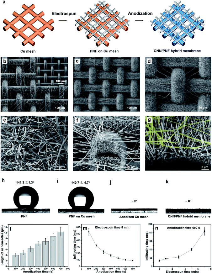
The hybrid membrane with wettability and topology anisotropy was composed of a hydrophilic nanoneedle mesh and a hydrophobic nanofiber network layer, which was fabricated by a simple electrospinning and electrochemical oxidation method. The fabrication process is illustrated in Fig. 1a. Firstly, a layer of poly(vinylidene fluoride-co-hexafluoropropylene) (PVDF-HFP) nanofibers (PNFs)38,39 was electrospun onto a copper (Cu) mesh. Then, the Cu mesh covered with PNFs was electrochemically anodized and a layer of Cu(OH)2 nanoneedles (CNNs) grew up from the Cu mesh wire surface.40 These CNNs pierced through the PNF network, which formed a hybrid membrane41–44 with a CNN/PNF interleaving structure. Fig. 1b shows a scanning electron microscopy (SEM) image of the Cu mesh covered by PNFs. The pristine Cu mesh exhibits a smooth wire surface with an average pore size of about 75 μm (inset of Fig. 1b). After electrospinning, a layer of PNFs randomly distributed on the Cu mesh. Then, the Cu mesh covered with PNFs was put into an electrochemical cell for anodization in KOH solution at 100 mA current. After anodization, a layer of dense CNNs grew from the Cu mesh wires and pierced through the pores of the PNF network as the anodization time was prolonged (Fig. 1c–e). Therefore, an interleaving topology of CNNs/PNFs was formed, which was further confirmed by the sectional images cut by a focused ion beam (FIB) (Fig. 1f and g). X-ray diffraction (XRD) and energy dispersive spectroscopy (EDS) results indicate that the CNNs are orthorhombic-phase Cu(OH)2 nanocrystals (JCPDS card no. 13-420) (Fig. S1 and S2, ESI†). The length of the CNNs exhibited linear growth from ∼2.2 μm (50 s) to ∼12.4 μm (700 s) with increasing anodization time (Fig. 1l and S3, ESI†). Correspondingly, the pore size of the anodized Cu meshes decreased from ∼75 μm to ∼50 μm as the anodization time increased from 0 s to 700 s (Fig. S4, ESI†). It is noted that anodization times over 700 s are not discussed because the CNN growth became inordinate and some dissociated Cu(OH)2 sediments adhered onto the PNFs (Fig. S5, ESI†). These results demonstrate that a CNN and PNF hybrid membrane with an interleaving topology could be fabricated by a simple electrospinning and subsequent anodization method.
Besides the CNN/PNF interleaving topology, the hybrid membrane also shows anisotropic wettability. The PNF network and pristine Cu mesh with PNFs, and the Cu(OH)2 mesh and the CNN/PNF hybrid membrane showed high hydrophobicity (141.3 ± 1.3° and 140.7 ± 4.7°) and hydrophilicity (∼0°), respectively (Fig. 1h–k). Meanwhile, for the hybrid membrane, the wetting behaviour was influenced by the length of the CNNs as well as the PNF density. Firstly, the infiltration time of the hybrid membrane decreased from 560 to 93 ms with increasing anodization time from 100 s to 700 s (fixed electrospinning time of 5 minutes) (Fig. 1m and S6, ESI†). Secondly, the infiltration time increased from 31 to 217 ms when the electrospinning time was increased from 0 to 7 minutes (fixed anodization time of 600 s) (Fig. 1n and S7, ESI†). The critical thickness of the electrospun membrane for effective droplet penetration was ∼2.6 μm when the electrospinning time was 7 minutes. If the electrospinning time was longer than 7 minutes, water could not infiltrate the hybrid membrane (Fig. S8, ESI†). This is because the PNFs became so overcrowded that CNNs were not able to grow out of the PNF network due to the very small and winding pores (Fig. S9 and S10, ESI†). These results demonstrated that the water infiltration rate could be tuned by regulating the structural parameters of the CNNs and PNFs. The hybrid structures with appropriate anisotropic wettability would significantly impact the performance of fog collection.
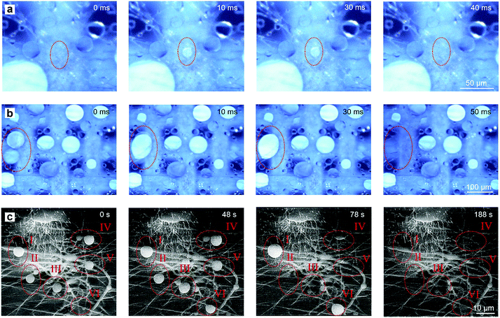
The fog collection process of the as-fabricated hybrid membrane is shown in Fig. 2. When the hybrid membrane was in a foggy environment, the fog droplets that encountered the membrane would be collected and experience several stages including droplet capture, growth, coalescence, directional transportation and collection. Fig. 2a and b are real processes of fog collection recorded by a stereomicroscope with a high-speed camera (for the dynamic phenomenon, see ESI Video†). Firstly, fog droplets randomly encountered the membrane and were captured by the surface. Then, two contact modes occurred. One was that the fog droplets contacted the CNN/PNF interleaving area, where the CNNs pierced out of the PNF network. Owing to the hydrophilicity of the CNNs, the droplets were directly and rapidly absorbed into the underlying mesh within 40 ms (Fig. 2a). The other case was that the droplets were captured on the vacant area of the mesh pores where only suspending PNFs existed (Fig. 2b). Then, smaller fog droplets on the PNFs grew up and coalesced into a larger water drop if they met. Once the margin of the growing larger drop contacted the CNNs, it would immediately be absorbed into the CNN mesh due to hydrophilic capillary force (Fig. 2b). With an increasing amount of absorbed water, the CNN mesh would be completely wetted and form a continuous water film underneath the hydrophobic PNF network. After formation of the water film, the fog collection process became steady and the fog droplets that contacted the membrane would be continuously and directionally transported from the hydrophobic PNF side to the hydrophilic CNN mesh side (Fig. S11, ESI†). Nevertheless, the droplets were hard to observe with an optical microscope after the water film formed because the contrast of the droplets and the water film was very weak. In order to more clearly monitor the fog droplet directional transportation process after the formation of a water film, we further observed the dynamic transportation process in an ESEM (Fig. 2c). The ESEM could provide a saturated vapour atmosphere with relatively low temperature, such that the water vapour would condense into tiny droplets on the membrane surface. Although a water film existed underneath the PNF network, the PNFs and the piercing-through CNNs were still exposed rather than submerged due to the hydrophobic confinement effect of the PNF network (Fig. S11, ESI†). These exposed CNNs and PNFs enlarged the windward area, which could effectively improve the fog capture chances in a real environment. It was seen that condensed water droplets firstly appeared on PNFs I–VI. Very like the two modes that Fig. 2a and b indicated, these growing droplets were either directly absorbed (I, V and VI) or coalesced with neighboring droplets and then absorbed (II, III and IV). It is noted that this water droplet condensation process (Fig. 2c) was much slower than directly foggy airflow (Fig. 2a and b), which resulted in the time scale difference. The above results demonstrated that the hybrid membrane with hydrophilic CNN and hydrophobic PNF interleaving structures could continuously capture, directionally transport and collect fog droplets.
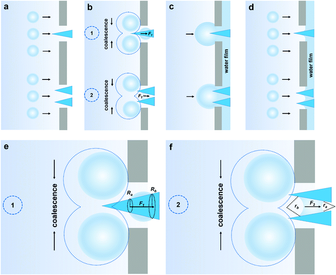
According to the structural features and fog collection phenomenon, the mechanism of directional fog collection of the hybrid membrane was proposed. When a foggy airflow encountered the hybrid membrane, the tiny fog droplets would randomly be captured by either the CNNs or PNFs. According to the Kelvin equation:45
 | (1) |
 | (2) |
 | (3) |
 | (4) |
 | (5) |
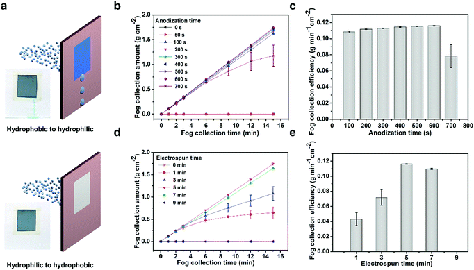
The above analysis demonstrates that the hydrophobic/hydrophilic hybrid membrane can realize efficient unidirectional fog collection. Then, we further investigated the impact of the structural configuration to the fog collection performance. The CNN/PNF hybrid membrane was vertically fixed on a slotted mould, which was used to characterize the unidirectional transportation property and fog collection performance (Fig. 4a). When fog was blown onto the hybrid membrane, it was seen that water was always collected and transported from the hydrophobic PNF side to the hydrophilic CNN side, and not vice versa. Then, we studied the fog collection performance of the hybrid membrane with different structures. Firstly, the unidirectional fog collection ability was impacted by the configuration of the CNNs. In this case, we fixed the electrospinning time at 5 minutes and studied the relationship between the CNN structure and fog collection efficiency. It is seen that the fog collection efficiency firstly increased and then decreased with increasing anodization time from 0 to 700 s (Fig. 4b and c). When the anodization time was 0–50 s, no water was directionally collected on the hydrophilic mesh side because the Cu(OH)2 crystals were too small to pierce through the hydrophobic PNF network. In this case, the fog droplets were almost completely intercepted by the hydrophobic PNFs and no water was obtained. If the anodization time was increased from 100 s to 600 s, the CNNs grew longer and longer and gradually pierced through the PNF network, and then the hydrophilic/hydrophobic alternate configuration formed. As a result, evident directional fog collection was achieved and the collection efficiency increased from 0.108 g min−1 cm−2 (100 s) to 0.116 g min−1 cm−2 (600 s). But this increasing efficiency trend dropped dramatically once the anodization time was over 700 s. This is because a longer anodization time resulted in overgrowth of the CNNs such that a number of secondary Cu(OH)2 nanocrystals pervaded and attached onto the hydrophobic PNFs (Fig. S5, ESI†). Thus, the hydrophobicity of the PNFs decreased and directional transportation was disabled.
Besides the configuration of the CNNs, the influence of the hydrophobic PNF density was also studied through tuning the electrospinning time (fixed anodization time of 600 s) (Fig. 4d and e). It is seen that the directional fog collection efficiency also rose at first and then decreased. CNN mesh alone without the PNFs could not achieve directional transportation of fog water. When the electrospinning time was increased from 1 to 3 minutes, a very sparse PNF network with relative larger pores formed on the Cu(OH)2 mesh. Then, directional fog transportation and collection was achieved. On further prolonging the electrospinning time to 5 minutes, a thin layer of PNF network with appropriate smaller pores formed and abundant CNNs protruded out from the interweaved network pores. This hybrid membrane with an alternate hydrophobic PNF/hydrophilic CNN interleaving structure exhibited the highest directional fog collection efficiency of 0.116 g min−1 cm−2. When the pore size of the network was further decreased through extending the electrospinning time to 7 minutes, the fog collection performance fell to 0.110 g min−1 cm−2 because there were less CNNs protruding out of the fiber network. If the electrospinning time was beyond 7 minutes, the PNF network became so dense that no CNNs could pierce through the network pores and be exposed (Fig. S10, ESI†). As a result, the directional fog collection capability decayed because the fog airflow facing the hydrophobic PNF side could not contact the hydrophilic CNNs. Therefore, the hybrid membrane with construction parameters of an anodization time of 600 s and an electrospinning time of 5 minutes was chosen in consideration of the optimized directional fog-collection performance. This performance (0.116 g min−1 cm−2) ranks rather highly in comparison to reported results (Fig. S13, ESI†).
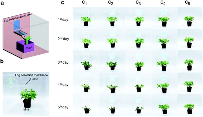
The most crucial requirement of fog collection materials is in agriculture. Therefore, we designed a simulated greenhouse to test the fog collecting and irrigating applicability of the as-fabricated hydrophilic CNN/hydrophobic PNF hybrid membrane (Fig. 5). Mint was selected as a model plant because it is a plant that is cultivated worldwide and is easy to farm with sufficient water. We made several identical transparent glass chambers (30 × 30 × 30 cm3) with a small window (4.5 × 6.0 cm2) in each chamber, which served as mini greenhouses. Then, five control experiments of mint cultivation were parallelly conducted. They were (c1) blank open window, (c2) hydrophilic CNN mesh window (without hydrophobic PNFs), (c3) and (c4) as-fabricated hydrophilic CNN/hydrophobic PNF hybrid membranes with the hydrophobic PNF side inward and outward, respectively, and (c5) normal irrigation sample. For samples c1–c4, no water was supplied, except for fog wind which was provided for half an hour every two days to simulate the morning fog environment. For c1 with an open window, the fog was directly blown into the chamber, but fog water could not be obtained by the roots of the mint. For c2 with only the CNN mesh, again, no water could be obtained by the mint due to the absence of directional fog collection ability. For c3, the mint could again not collect water because the hydrophobic PNFs were on the inward side of the window. It is seen that the mint plants grown in chambers c1–c3 were all dry and dead after 5 days because no fog water was collected. As for c4, abundant water was directly collected every two days and the mint grew very well. It is seen that c4 had no observable difference compared to the normally irrigated c5 sample, which shows that the as-fabricated hybrid membrane is very competent at fog collection for irrigating plants. A side benefit of the hybrid membrane is that the micropores bestow the mini greenhouse with a breathable property, which is important for maintaining a suitable cultivation microenvironment with appropriate gas concentrations and humidity.
Conclusions
Inspired by natural fog-collecting surfaces, such as a desert beetle's back and cactus spines, we designed a hybrid membrane with both wettability and topology anisotropy, which exhibited excellent unidirectional fog collection capability. The hybrid membrane consists of a hydrophilic CNN and hydrophobic PNF alternate structure that is fabricated by a simple electrospinning and anodization method. Owing to its special wettability and topology anisotropy, the hybrid membrane provided a cooperative mechanism of fog droplet capture, growth, coalescence, directional transportation and collection. Actual plant cultivation experiments demonstrated that the hybrid membrane could collect sufficient fog water for normal irrigation requirements of plants in foggy areas. By virtue of the outstanding fog collection capability, low material costs and simple manufacturing procedures, this hybrid membrane should be a competitive candidate for relieving the global freshwater shortage crisis in drought areas.Materials and methods
Materials
Copper mesh (200 mesh number, Huaxin Hardware Screen Factory, China), poly(vinylidene fluoride-co-hexafluoropropylene) (PVDF-HFP, Mw ∼ 400![[thin space (1/6-em)]](https://www.rsc.org/images/entities/char_2009.gif) 000, Sigma-Aldrich), dimethylacetamide (DMAc), acetone, ethanol, and potassium hydroxide (KOH) (A.R., Beijing Chemical Works, China) were used without further treatment.
000, Sigma-Aldrich), dimethylacetamide (DMAc), acetone, ethanol, and potassium hydroxide (KOH) (A.R., Beijing Chemical Works, China) were used without further treatment.
Fabrication of the hybrid membrane
Copper mesh was ultrasonically cleaned in acetone, ethanol, and distilled water, successively, to remove contaminants. PVDF-HFP was dissolved in solvent (acetone/DMAc, 7![[thin space (1/6-em)]](https://www.rsc.org/images/entities/char_2009.gif) :
:![[thin space (1/6-em)]](https://www.rsc.org/images/entities/char_2009.gif) 3 w/w) to form a 15% spinning solution. The copper mesh was attached onto the drum collector (radius 13.5 cm) surface of an electrospinning instrument. The distance between the electrospun needle tip and the rolling drum collector was 25 cm, the voltage was set at 25 kV, and the rolling speed was 200 rpm. After electrospinning, the copper mesh/nanofiber composite membrane was pre-wetted with ethanol and then put into an aqueous solute of 2 M KOH at ambient temperature to execute electrochemical oxidation at 100 mA (CHI660E, CH Instruments Ins.).
3 w/w) to form a 15% spinning solution. The copper mesh was attached onto the drum collector (radius 13.5 cm) surface of an electrospinning instrument. The distance between the electrospun needle tip and the rolling drum collector was 25 cm, the voltage was set at 25 kV, and the rolling speed was 200 rpm. After electrospinning, the copper mesh/nanofiber composite membrane was pre-wetted with ethanol and then put into an aqueous solute of 2 M KOH at ambient temperature to execute electrochemical oxidation at 100 mA (CHI660E, CH Instruments Ins.).
Measurement of the unidirectional fog collection of the hybrid membrane
The hybrid membranes (3.5 × 4.0 cm2) were vertically fixed on a slotted mould to characterize their unidirectional transportation properties and fog collection performance. The fog flow velocity was 7.262 g min−1 cm−2 provided by a humidifier.Characterization
The surface structure of the hybrid membrane was characterized by environmental scanning electron microscopy (Quanta 250FEG, FEI). The copper mesh and anodized mesh were characterized by XRD (XRD-6000, Shimadzu). The contact angles were measured with an optical contact angle measuring device (JC2000D3M, Powereach) at ambient temperature. A high-speed camera (I-speed 3 series, Olympus) was used for observing the water droplet (∼4 μL) dynamic infiltration process on the hybrid membrane. A stereomicroscope (AZ100, Nikon) and environmental scanning electron microscopy (Quanta 200FEG, FEI) were used for observing the fog droplet collection dynamic process on the hybrid membrane. A section of the membrane was cut and observed by focused ion beam (FIB) (Auriga, Zeiss). A temperature humidity meter (TM-184, Tenmars) was used for measuring the humidity.Conflicts of interest
There are no conflicts to declare.Acknowledgements
The authors acknowledge the National Natural Science Foundation of China (NSFC) (Grant No. 21774005, 21433012, 21374001, and 51871014), the National Natural Science Foundation for Outstanding Youth Foundation, the Fundamental Research Funds for the Central Universities, the National Program for Support of Top-notch Young Professionals, and the 111 project (Grant No. B14009).Notes and references
- P. Gandhidasan, H. I. Abualhamayel and F. Patel, Aerosol Air Qual. Res., 2018, 18, 200–213 CrossRef.
- M. M. Mekonnen and A. Y. Hoekstra, Sci. Adv., 2016, 2, e1500323 CrossRef PubMed.
- M. Verdaguer, M. Molinos-Senante, N. Clara, M. Santana, W. Gernjak and M. Poch, Sci. Total Environ., 2018, 624, 1308–1315 CrossRef CAS PubMed.
- N. Joshi, R. Naresh Dholakiya, M. Anil Kumar and K. H. Mody, Environ. Prog. Sustainable Energy, 2017, 36, 1458–1465 CrossRef CAS.
- B. E. Logan, Environ. Sci. Technol. Lett., 2017, 4, 197 CrossRef CAS.
- M. A. Martinez-Mate, B. Martin-Gorriz, V. Martínez-Alvarez, M. Soto-García and J. F. Maestre-Valero, J. Cleaner Prod., 2018, 172, 1298–1310 CrossRef CAS.
- H. Kim, S. Yang, S. R. Rao, S. Narayanan, E. A. Kapustin, H. Furukawa, A. S. Umans, O. M. Yaghi and E. N. Wang, Science, 2017, 358, 430–434 CrossRef.
- Y. Y. Song, Y. Liu, H. B. Jiang, S. Y. Li, C. Kaya, T. Stegmaier, Z. W. Han and L. Q. Ren, Nanoscale, 2018, 10, 3813–3822 RSC.
- A. R. Parker and C. R. Lawrence, Nature, 2001, 414, 33–34 CrossRef CAS.
- Y. Zheng, H. Bai, Z. Huang, X. Tian, F. Q. Nie, Y. Zhao, J. Zhai and L. Jiang, Nature, 2010, 463, 640–643 CrossRef CAS.
- J. Ju, H. Bai, Y. Zheng, T. Zhao, R. Fang and L. Jiang, Nat. Commun., 2012, 3, 1247 CrossRef PubMed.
- M. K. Chaudhury and G. M. Whitesides, Science, 1992, 256, 1539–1541 CrossRef CAS PubMed.
- S. Daniel, M. K. Chaudhury and J. C. Chen, Science, 2001, 291, 633 CrossRef CAS PubMed.
- H. Geng, H. Bai, Y. Fan, S. Wang, T. Ba, C. Yu, M. Cao and L. Jiang, Mater. Horiz., 2018, 5, 303–308 RSC.
- P. Renvoisé, J. W. M. Bush, M. Prakash and D. Quéré, Europhys. Lett., 2009, 86, 64003 CrossRef.
- A. Lee, M. W. Moon, H. Lim, W. D. Kim and H. Y. Kim, Langmuir, 2012, 28, 10183–10191 CrossRef CAS PubMed.
- P. Comanns, G. Buchberger, A. Buchsbaum, R. Baumgartner, A. Kogler, S. Bauer and W. Baumgartner, J. R. Soc., Interface, 2015, 12, 20150415 CrossRef.
- S. Feng, S. Wang, Y. Tao, W. Shang, S. Deng, Y. Zheng and Y. Hou, Sci. Rep., 2015, 5, 10067 CrossRef CAS PubMed.
- C. Liu, J. Sun, J. Li, C. Xiang, L. Che, Z. Wang and X. Zhou, Sci. Rep., 2017, 7, 7552 CrossRef.
- H. Zhou, M. Zhang, C. Li, C. Gao and Y. Zheng, Small, 2018, 14, 1801335 CrossRef.
- M. Cao, J. Ju, K. Li, S. Dou, K. Liu and L. Jiang, Adv. Funct. Mater., 2014, 24, 3235–3240 CrossRef CAS.
- J. Ju, X. Yao, S. Yang, L. Wang, R. Sun, Y. He and L. Jiang, Adv. Funct. Mater., 2014, 24, 6933–6938 CrossRef CAS.
- F. Bai, J. Wu, G. Gong and L. Guo, Adv. Sci., 2015, 2, 1500047 CrossRef PubMed.
- D. Chen, J. Li, J. Zhao, J. Guo, S. Zhang, T. A. Sherazi, Ambreen and S. Li, J. Colloid Interface Sci., 2018, 530, 274–281 CrossRef CAS PubMed.
- J. Ju, K. Xiao, X. Yao, H. Bai and L. Jiang, Adv. Mater., 2013, 25, 5937–5942 CrossRef CAS PubMed.
- T. Xu, Y. Lin, M. Zhang, W. Shi and Y. Zheng, ACS Nano, 2016, 10, 10681–10688 CrossRef CAS.
- H. Bai, C. Zhang, Z. Long, H. Geng, T. Ba, Y. Fan, C. Yu, K. Li, M. Cao and L. Jiang, J. Mater. Chem. A, 2018, 6, 20966–20972 RSC.
- Z. X. Huang, X. Liu, J. Wu, S. C. Wong and J. P. Qu, Mater. Lett., 2017, 211, 28–31 CrossRef.
- C. Song, L. Zhao, W. Zhou, M. Zhang and Y. Zheng, J. Mater. Chem. A, 2014, 2, 9465–9468 RSC.
- H. Bai, X. Tian, Y. Zheng, J. Ju, Y. Zhao and L. Jiang, Adv. Mater., 2010, 22, 5521–5525 CrossRef CAS PubMed.
- Y. Chen and Y. Zheng, Nanoscale, 2014, 6, 7703–7714 RSC.
- X. H. He, W. Wang, Y. M. Liu, M. Y. Jiang, F. Wu, K. Deng, Z. Liu, X. J. Ju, R. Xie and L. Y. Chu, ACS Appl. Mater. Interfaces, 2015, 7, 17471–17481 CrossRef CAS PubMed.
- X. Tian, Y. Chen, Y. Zheng, H. Bai and L. Jiang, Adv. Mater., 2011, 23, 5486–5491 CrossRef CAS PubMed.
- Y. Wang, L. Zhang, J. Wu, M. N. Hedhili and P. Wang, J. Mater. Chem. A, 2015, 3, 18963–18969 RSC.
- L. Zhang, J. Wu, M. N. Hedhili, X. Yang and P. Wang, J. Mater. Chem. A, 2015, 3, 2844–2852 RSC.
- H. Bai, L. Wang, J. Ju, R. Sun, Y. Zheng and L. Jiang, Adv. Mater., 2014, 26, 5025–5030 CrossRef CAS PubMed.
- K. Yin, H. Du, X. Dong, C. Wang, J. A. Duan and J. He, Nanoscale, 2017, 9, 14620–14626 RSC.
- L. Hou, L. Wang, N. Wang, F. Guo, J. Liu, Y. Chen, J. Liu, Y. Zhao and L. Jiang, NPG Asia Mater., 2016, 8, e334 CrossRef CAS.
- Z. Wang, Y. Li, S. Li, J. Guo and S. Zhang, Chem. Commun., 2018, 54, 10954–10957 RSC.
- M. Qiu, N. Wang, Z. Cui, J. Liu, L. Hou, J. Liu, R. Hu, H. Zhang and Y. Zhao, J. Mater. Chem. A, 2017, 6, 817 RSC.
- Z. Wang, X. Yang, Z. Cheng, Y. Liu, L. Shao and L. Jiang, Mater. Horiz., 2017, 4, 701 RSC.
- F. Ren, G. Li, Z. Zhang, X. Zhang, H. Fan, C. Zhou, Y. Wang, Y. Zhang, C. Wang and K. Mu, J. Mater. Chem. A, 2017, 5, 18403 RSC.
- M. Cao, J. Xiao, C. Yu, K. Li and L. Jiang, Small, 2015, 11, 4379–4384 CrossRef CAS.
- X. Tian, H. Jin, J. Sainio, R. H. A. Ras and O. Ikkala, Adv. Funct. Mater., 2015, 24, 6023–6028 CrossRef.
- H. Y. Erbil, Surface Chemistry: Of Solid and Liquid Interfaces, Blackwell Pub., 2006 Search PubMed.
- É. Lorenceau and D. Quéré, J. Fluid Mech., 2004, 510, 29–45 CrossRef.
- X. Ma, M. Cao, C. Teng, H. Li, J. Xiao, K. Liu and L. Jiang, J. Mater. Chem. A, 2015, 3, 15540–15545 RSC.
- Q. Wang, B. Su, H. Liu and L. Jiang, Adv. Mater., 2014, 26, 4889–4894 CrossRef CAS PubMed.
- M. Cao, K. Li, Z. Dong, C. Yu, S. Yang, C. Song, K. Liu and L. Jiang, Adv. Funct. Mater., 2015, 25, 4114–4119 CrossRef CAS.
- B. Lefevre, A. Saugey, J. L. Barrat, L. Bocquet, E. Charlaix, P. F. Gobin and G. Vigier, J. Chem. Phys., 2004, 120, 4927–4938 CrossRef CAS PubMed.
Footnotes |
| † Electronic supplementary information (ESI) available. See DOI: 10.1039/c8ta10615k |
| ‡ Rongjun Hu and Nü Wang contributed equally to this work. |
| This journal is © The Royal Society of Chemistry 2019 |

