 Open Access Article
Creative Commons Attribution 3.0 Unported Licence
Mapping outcomes of liquid marble collisions†
Thomas C.
Draper
 a,
Claire
Fullarton
 a,
Richard
Mayne
 a,
Neil
Phillips
 a,
Giacomo E.
Canciani
 b,
Ben P. J.
de Lacy Costello
 ac and
Andrew
Adamatzky
 *a
*a
aUnconventional Computing Laboratory, University of the West of England, Bristol, BS16 1QY, UK. E-mail: Andrew.Adamatzky@uwe.ac.uk
bCEA Nuclear Energy Division, Research Department of Mining and Fuel Recycling, Analysis Method Establishment Commission (CETAMA), 30207, Bagnols-sur-Céze, France
cInstitute of Biosensing Technology, Centre for Research in Biosciences, University of the West of England, Bristol, BS16 1QY, UK
First published on 4th April 2019
Abstract
Liquid marbles (LMs) have many promising roles in the ongoing development of microfluidics, microreactors, bioreactors, and unconventional computing. In many of these applications, the coalescence of two LMs is either required or actively discouraged, therefore it is important to study liquid marble collisions and establish parameters which enable the desired collision outcome. Recent reports on LM coalescence have focused on either two mobile LMs colliding, or an accelerating LM hitting a sessile LM with a backstop. A further possible scenario is the impact of a mobile LM against a non-supported static LM. This paper investigates such a collision, using high-speed videography for single-frame analysis. Multiple collisions were undertaken whilst varying the modified Weber number (We*) and offset ratios (X*). Parameter ranges of 1.0 < We* < 1.4 and 0.0 < X* < 0.1, resulted in a coalescence rate of approximately 50%. Whereas, parameter ranges X* > 0.25, and We* < 0.95 or We* > 1.55 resulted in 100% non-coalescence. Additionally, observations of LMs moving above a threshold velocity of 0.6 m s−1 have revealed a new and unusual deformation. Comparisons of the outcome of collisions whilst varying both the LM volume and the powder grain size have also been made, revealing a strong link. The results of this work provide a deeper understanding of LM coalescence, allowing improved control when designing future collision experiments.
1 Introduction
Liquid marbles (LMs) consist of tiny droplets of liquid, coated in a hydrophobic powder. Although LMs have commonly been exploited by nature,1 their first human applications were reported by Aussillous and Quéré in 2001.2 The powder coating of a LM effectively makes the droplet non-wetting on many surfaces (both solid and liquid3) – a feature that has made them a topic of increasing interest in recent years,4–9 in fields as diverse as biomedical microfluidics10 to unconventional computing.11The coating of a LM is non-continuous and imperfect.12 As a result of this, it is possible for LMs to interact with gases in both directions (i.e. evaporation and diffusive absorption). This was demonstrated by Tian et al. in 2010, with their variety of gas-sensing LMs.13 Although the marble's coating is non-uniform and porous, LMs are known to resist coalescence when pressed together.14 This effect can be attributed to the hydrophobic nature of the powder which protects the liquid core and prevents casual coalescence. Controlled coalescence is a crucial factor in the design of microreactors and digital microfluidics. As such, an understanding of the parameters controlling the coalescence of LMs is essential.
Despite the hydrophobic powder barrier, several studies reporting and investigating the coalescence of LMs have been published in recent years.15,16 The impact resulting from the vertical collision of two LMs has been reported on by Planchette et al.,17 and more recently by Jin et al. in 2018.18 In both cases, a LM was dropped from a known height onto a stationary LM. These impacts were monitored by high-speed camera, using individual frames to determine speed and impact behaviour. The impact speed required to initiate coalescence was observed to depend directly on particle size, droplet size, impact velocity, and the nature of the LMs powder coating and liquid core. The velocity required to initiate coalescence has been reported to vary from 0.29 m s−1 to 0.68 m s−1.17–19
Magnetic fields have proven to be a popular way to ‘open’ and ‘close’ LMs, but they have also been used to initiate coalescence. The magnetic properties of a LM can be enhanced by the use of either a magnetic coating,20 or by inclusion of magnetic nanopowders suspended in the liquid core.21 In the case of a magnetic coating, the LMs can be partially deshielded by using a magnet to draw the coating to one extremity of the LM, thereby exposing the liquid core. (Acoustic waves have also been used to facilitate controllable deshielding and reshielding of LMs.22) This enables easy coalescence by allowing two unshielded LMs to touch. When the core of the LM is magnetic, the marbles are propelled at speed towards each other using magnets, allowing them to merge by the high impact energy overcoming the powder coating.
An alternative method for the coalescence of LMs is through the use of DC electric fields.23 In this technique, two LMs are placed in contact with each other on an insulating surface and an electrode in each LM allows a chosen voltage to be applied. Using 8.8 μL LMs coated with PTFE, the two LMs coalesce quickly within 10 ms once the voltage reaches circa 300 V. Liu et al. demonstrated that, through a judicious placement of the electrodes, it was also possible to coalesce chains of multiple LMs using the same technique.
Another recent technique for LM coalescence proceeds through the collision of floating LMs.24 Floating LMs can be self-propelled or have their movement externally influenced. Self-propelled LMs usually exploit the Marangoni effect by modifying the surface tension of the supporting medium near the LM via gaseous diffusion of the LMs core.5 More recently, sulphuric acid LMs have been shown to self-propel on water, due to the diffusion of water vapour into the LM.25 The resulting dilution is exothermic and so causes spot heating, with the resulting thermo-capillary flow causing gentle LM movement. A more controlled direction can be obtained by using an infrared laser to heat a LM coated in carbon black,26 or by initiating global Marangoni flows in the liquid substrate.27
The potential for use of LMs in microfluidics is growing rapidly,28 as is their use in micro- and bio-reactors.10,29 This is because they hold many advantages over more traditional techniques, such as faster kinetics, reduced chemical cost, and discrete encapsulation (eliminating the contamination from the oil phase frequently used in digital microfluidics). In each of these fields coalescence of LMs, in order to mix chemicals, is often required. As such, the collision of two LMs was explored: one sessile and unobstructed, the other rolling horizontally on a collision course with the first. These induced collisions were observed by high-speed camera. By considering the size, coating, volume, velocity, Weber number (We), and offset ratio (X*) of these collisions, the parameters required for coalescence were investigated.
2 Experimental
Liquid marbles were prepared by rolling appropriately sized droplets of deionised water on a powder bed of ultra-high density polyethylene (PE) (Sigma-Aldrich, 3–6 × 10⁶ g mol−1, grain size approximately 100 μm). The droplets were measured and dispensed using an air-displacement micropipette. An appropriate coating was ensured by rolling the droplets for a minimum of five seconds, and until a fully-coated LM was visually observed.The experimental collision rig was composed of a ramp and collision zone. It was designed using SolidWorks 2017 (Dassault Systèmes), before being converted into an STL file (deviation tolerance: 0.0108 mm, angle tolerance: 0.500°). The design was then printed with an Ultimaker 2, using polylactic acid (PLA, Verbatim 2.85 mm 3D Printer Filament) as the print material, and a vertical layer height of 60 μm. The printed collision rig was cleaned by hand, with the ramp being wet-sanded with 600 grit paper.
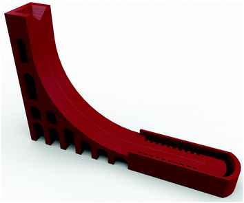
The ramp design evolved through several stages before concluding with the design shown in Fig. 1. Early, cup-shaped, designs caused issues in determining LM speed due to the variable distance between the LM and the camera. This limitation was removed through the addition of an accelerating slope and a level collision zone. In order to ensure LM collision, a 0.20 mm deep semi-circular groove was implemented, which channelled the accelerating LMs. To simplify pixel-to-metre unit conversion, markers were designed into the 3D print at 5 mm intervals. The CAD file can be found in the ESI.†
For each performed collision a freshly prepared LM was placed in the collision zone at the bottom of the ramp. A second LM was placed at the top of the ramp and rolled down. This roll allowed the LM to gain velocity, before colliding with the stationary LM (impact velocity was between 0.15 m s−1 and 1.11 m s−1). By adjusting the location of the static LM, both the impact velocity (and thereby energy and Weber number) and offset ratio could be controlled. Collisions were monitored with a high-speed camera (fps1000HD-256, Imagetec Ltd), equipped with a macro zoom lens (#52–274, 18–108 mm, f/2.8, Edmund Optics). Footage was recorded at 1000 frames per second, with a resolution of 1280 × 720 pixels. The camera was positioned vertically above the experimental collision zone and aligned using spirit levels, affording a top-down view.
The recorded frames were extracted and processed with a custom script in MatLab R2018a (MathWorks). This enabled the determination of both the impact velocity and offset ratio of the LMs. Sequential frames of a known time interval were imported as RGB images, which were segmented both via the L*a*b* (CIELAB) colour space transform and K-means clustering method; this involved converting the images to three-layered RGB images (one luminosity and two chromaticity layers) before segmenting the image into a user-defined number of colours – three, in this instance – and returning indices for each cluster detected. This step split the images into separate colour spaces and served to separate the pixels representing marbles (white) from their background and sources of interference (e.g. reflections). Circles were then detected and labelled in both frames using a two-stage circle Hough transform, from user-defined values for circle radius range and a sensitivity factor. The trajectory of the mobile LM was then calculated through a comparison of XY coordinates and the time interval between different frames. The offset ratio was calculated using the trajectory of the mobile LM and the coordinates of the stationary marble using trigonometry. Example outputs of this script, and the code itself, can be found in the ESI.†
3 Results & discussion
3.1 Weber number
The collision between two droplets is typically defined using the Weber number. This practice has transferred into the field of LMs. The Weber number is a dimensionless value correlated to kinetic energy, which is used to compare a fluid's inertia to its surface tension. The Weber number (We) is defined in (1), where r is the radius, ρeff is the effective density, ν is the velocity, and γeff is the effective surface tension. | (1) |
Herein, the modified Weber number (We*) is used. We* is the ratio between the kinetic energy (Ek) of a LM (or droplet) and its surface energy (Es):
 | (2) |
3.2 Offset ratio
The offset ratio, X*, is a dimensionless description of the amount of overlap that two colliding LMs have at impact (succinctly described by Jin et al.18). It is defined by X* = x/D; where x is the distance between the centres of the two LMs, perpendicular to the direction of motion, and D is the diameter of the LM. The offset ratio ranges from 0 (a direct hit) to 1 (a near miss), as demonstrated in Fig. 2.3.3 Effective surface tension
The effective surface tension (γeff) of a LM is affected by the particles on the surface of the droplet, and as such deviates from the value for pure deionised water. There are many ways of determining the surface tension of a LM, including the pendant marble technique30 and the capillary rise technique.31 A particularly fascinating technique has been demonstrated by Ooi et al. using X-ray computerised micro-tomography to image the interface of a floating LM,32 and thereby determine the three-phase contact line. All of these techniques measure the static surface tension, though it should be noted that, as collisions are a dynamic process, the dynamic surface tension could also be a factor. This is generally calculated by observing oscillation frequencies of mobile LMs, such as with the catapult mechanism33 or surface rebounds.34The surface tension of our PE coated LMs was determined by using the puddle height method, as established by Bormashenko et al.35 The principle of this technique is that as a LM's size is increased, a maximum height is reached. Beyond this, a geometric distortion of the LM into a ‘puddle’ shape occurs. This maximum height is caused by a balance between surface tension and gravity, as described in (3).
 | (3) |
Here, ρ is the density of the core (i.e. deionised water), g is acceleration due to gravity, θ is the apparent contact angle, and Hmax is the maximum height of the LM. During this experiment, Hmax is extrapolated by studying the heights of LMs with varying volumes.
By fitting the data to a line with the general formula y = a − b·cx, and applying (3), it was possible to calculate the effective surface tension (γeff) of the LMs as 88.2 ± 3.5 mN m−1. Reported literature values for γeff vary considerably.17,30–33,35–40 The value reported during our study can be attributed to both the molecular weight and particle size of the PE used, which is much larger than that used by many other groups (a 100 μm particle powder will provide a greater hydrophobic distance for water to traverse before exiting the LM when compared to a 2 μm particle powder).35 Variations in the identity, particle size, and nano-scale surface features of the various powder coatings used hinders direct comparisons.
3.4 Effective density
As the particle coating needs taking into consideration, the effective density of LMs is not the same as that of water. An elegant calculation towards a theoretical value for LM density was devised by Supakar et al.41 However, the results of their calculations didn’t correlate perfectly with their experimental findings. This discrepancy was attributed to an uncertainty in the particle packing and number of layers on the surface of the LM which led to a variation of circa 10% between theoretical and experimental values. Additional reports have reiterated the complications of the theoretical determination of effective density, such as aggregated particles, air pockets and the non-uniformity of the powder coating.30,31,40,42During this study, we have taken a more tractable approach. By considering the mathematical volume of a sphere (V = 4πr3/3) and incorporating it into the standard equation for the density of an object (ρ = m/V), it was possible for us to correlate the density of a LM, ρeff, to its mass, m, and radius, r, as shown in (4). Using this, it is only required to know the mass of the LM (which can be easily weighed) and its radius.
 | (4) |
The radius of the LM can be considered to be the sum of the radius of the uncoated droplet and the diameter of particles coating the droplet n times. As such, it is possible to reexpress (4), as shown in (5), where rd is the radius of the uncoated and naked droplet (calculated from V = 4/3πr3), n is the number of layers in the powder coating, and dp is the diameter of the particles in the powder coating.
 | (5) |
There are drawbacks to this system for evaluating the effective density of LMs. Firstly, it assumes there are no packing forces. However, when the packing ratio is unknown we believe more error can be introduced by including said forces (which would inevitably be estimated at best) in the calculations, than not. Secondly, (5) assumes that the LM is a perfect sphere. Although this is known to be untrue, especially for larger sessile LMs, LMs are approximated deformed spheres. This approximation holds very well with smaller LMs, and provides a convenient system for calculating LM volume. The final difficultly is knowing the values of n and, to a lesser extent, dp. The particle size distribution can be relatively easily ascertained with various techniques. However the best way to determine the number of layers in the powder coating is with X-ray computerised micro-tomography, using either a specialised X-ray machine32 or a synchrotron.43 More facile methods are to estimate it with microscopy and macro-photography. This however, is a shortcoming of all current techniques.
The effective density of our 15 μL PE LMs was calculated using (5). The mass, m, of an individual LM was determined to be 16.8 ± 0.1 mg by taking the combined average of 10 independent measurements. The radius of the uncoated droplet, rd, was deemed to be 1.53 ± 0.01 mm using sphere theory. Using macro-photographs of the LMs, the powder coating appeared to consist of one to two layers for our PE LMs; we therefore used n = 1.5. Particle diameter information was gathered using a scanning electron microscope (full details and images can be seen in the ESI†), and a value of dp = 102 μm was taken. Using these parameters yielded an effective density of 840 kg m−3. As expected, this density is lower than that of water. This difference arises from the PE particles (which have a lower density than water), as well as the presence of air pockets in the imperfect packing of the powder coating.
The volume (and thereby mass) of a LM, and the diameter of the particles coating it, both affect the LMs effective density. The calculated effective density of the LMs used in this paper can be seen in Table 1.
| Volume (μL) | Particle size (μm) | Mass (mg) | Effective density (kg m−3) |
|---|---|---|---|
| 15.0 | 102 ± 35 | 16.8 ± 0.1 | 840 |
| 10.0 | 102 ± 35 | 11.0 ± 0.1 | 795 |
| 15.0 | 63–90 | 15.6 ± 0.1 | 836 |
| 15.0 | 180–250 | 17.0 ± 0.2 | 638 |
3.5 Liquid marble collision processes
The collision of two LMs was conducted initially using 15 μL PE coated marbles. Experiments investigated the collision of a rolling LM with an equally-sized freestanding & stationary LM. On release, the higher LM rolled down the ramp, accelerating under gravity and thereby converting its potential energy into kinetic energy. The speed at impact was recorded using static frames of a known time difference moments before impact. Upon impact, one of three different non-coalescing scenarios can occur (or coalescence), each of which shall be described herein. Videos of each of these collision types are available in the ESI.†The most common scenario for a non-coalescing contact (0.05 < X* < 0.35) is shown in Fig. 3, and takes place as follows. On making contact with the static LM, the approaching LM deforms slightly into a disc shape, pressing against the static marble, as can be seen in Fig. 3b. This deformation arises from the soft nature of the liquid core, wherein the momentum of the rear exceeds that of the front of the LM (which was reduced upon impact). This deformed LM has a partial indentation in it, due to the liquid core being forced to the extremities. Simultaneously, a wave is seen to progress through the static LM, taking 5 ms to propagate from the point of impact to the far side. As the wave reaches the far end of the static LM, surface tension pulls the liquid at the extremities of the approaching disc-shaped LM back to the core. At the same time, the LM's momentum carries it up above the static LM, as seen in Fig. 3c. This lifting effect is aided by the fact that the front edge of the approaching LM is moving down, causing it to grip and ‘climb’ up the static LM – a similar effect has been observed when two LMs rolling in the same direction make contact.44 The approaching LM then climbs approximately halfway up the static LM, and slightly slows down. The reduction in velocity makes the LM more susceptible to the natural curvature of the static LM, causing it to follow the contours and roll off towards the side it is most inclined to, with a direction change of 20° to 50° (this can be seen in Fig. 3d). The static LM, on impact, rolls in the inverse direction away from the contact point. The roll only continues for half a turn however, before the LM loses the rotational element of its superposition and begins to slide. (It appears the rotation is prevented by the prolonged physical contact of the approaching LM.) The slide continues for another half-LM length (∼15 ms), after which the previously static LM rolls for another quarter of a rotation before halting. Interestingly, the LM then slowly (∼50 ms) rotates backwards for a fifth of a rotation, coming to its final resting state. This backwards rolling movement was observed in every non-coalescing impact event, negating the possibility of it being related to a LM self-balancing. Instead, we believe it to be related to the internal fluid dynamics, imparted by the impact.
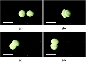 | ||
| Fig. 3 An example non-coalescing collision for 0.05 < X* < 0.35. Respective time differences from frame (a) are (a) 0 ms, (b) 7 ms, (c) 36 ms, and (d) 50 ms. The mobile LM is approaching from the right. The scale bars are 5 mm. The video is available in the ESI.† | ||
The two other scenarios for non-coalescing impacts occur when the offset ratio is at one of the two extremes. Fig. 4 shows the result of a collision if the offset ratio is relatively high (X* > 0.35): the stationary LM will also roll off to one side once impacted, as visible in Fig. 4d. When this happens, the exit trajectories are typically ±20°. This is possible because as the approaching LM ‘climbs’ up the static LM, it actually becomes airborne, resulting in a brief period with no physical contact between the two LMs (Fig. 4b). This allows the previously static LM to roll unhindered. The mobile LM maintains the majority of the kinetic energy, moving at nearly double the velocity of the previously static LM. The two LMs then roll to a stop, before a partial slow reverse roll.
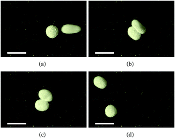 | ||
| Fig. 4 An example non-coalescing collision for X* > 0.35. Respective time differences from frame (a) are (a) 0 ms, (b) 12 ms, (c) 17 ms, and (d) 49 ms. The mobile LM is approaching from the right. The scale bars are 5 mm. The video is available in the ESI.† | ||
If the offset ratio is very close to zero (X* < 0.05), then on impact the approaching LM does not roll over and off to the side. Instead, whilst maintaining a forward direction of motion, it climbs up the static LM and flips itself into the air approximately 1 mm. This can be seen through a combination of frame analysis, focus blur, and light shadows in Fig. 5b. Simultaneously, the previously static LM rolls with a slightly higher initial lateral velocity. This creates a space behind it, into which the approaching LM lands (Fig. 5c). Both LMs then continue to roll for 1–2 LM lengths (Fig. 5d), before performing the previously described partial reverse roll and coming to rest.
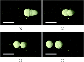 | ||
| Fig. 5 An example non-coalescing collision for X* < 0.05. Respective time differences from frame (a) are (a) 0 ms, (b) 11 ms, (c) 32 ms, and (d) 70 ms. The mobile LM is approaching from the right. The scale bars are 5 mm. The video is available in the ESI.† | ||
Whilst there was variation in the non-coalescing events, all impacts that did result in coalescence followed the same pathway, as demonstrated in Fig. 6, and in the video available in the ESI.† As the approaching LM nears the static LM, it is travelling at high speed (ν > 0.5 m s−1) and with a small offset ratio (generally X* < 0.1). At the moment of impact the particle-coated surfaces of both LMs are overcome, and the water cores make contact. Once this happens, surface tension drives the two water cores together, causing the approaching LM to be enveloped into the static LM (see Fig. 6b). The force of the impact causes a large wave to propagate throughout the entire static LM quickly (8 ms). At the same time, some of the kinetic energy of the approaching LM is carried onward, and the newly formed larger LM begins to roll along the same direction as the approaching LM. The newly formed LM is unusually shaped (Fig. 6c): it is an approximated prolate spheroid, with a small ‘tail’ protruding at the entry point of the originally approaching LM (comprised of the remnants of the original LM that was not taken into the bulk, though still completely connected to the bulk). As the newly formed LM rolls, the protrusion is rotated over the top of the LM and eventually comes into contact with the ground on the opposite side (Fig. 6d). This has the effect of acting like a brake: stopping the rotational motion after a half-turn, but not the translational motion. Consequently, the LM slides for half a marble length (around 5 mm in this case), before coming to a complete stop. No final backwards rolls were observed in any of the studied coalescing impacts. The deformed LM geometry resulting from coalescing collisions has not been previously reported, to the authors’ knowledge. Preliminary studies on the stability of this novel geometry have shown that the deformed LMs can be coaxed back to a regular shape (an oblate spheroid for LMs of this size) by repeated rolling.
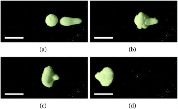 | ||
| Fig. 6 An example coalescing collision for X* < 0.1 and ν > 0.5 m s−1. Respective time differences from frame (a) are (a) 0 ms, (b) 5 ms, (c) 10 ms, and (d) 45 ms. The mobile LM is approaching from the right. The scale bars are 5 mm. The video is available in the ESI.† | ||
This final form of the recently coalesced LM is significantly deformed from the sphere or puddle normally associated with LMs. There is an increase of plasticity in the coating of the LM, which is caused by a change in the ratio of surface area to volume – which is itself brought on by the coalescence. This is better understood by considering a 15 μL LM with sufficient powder to coat an idealised spherical surface area of 29.4 mm2, when two such LMs coalesce they produce a new LM with a volume of 30 μL and a spherical surface area of 46.7 mm2. However the LM coating also combines, providing the new LM with sufficient powder to cover 58.8 mm2. This excess powder causes the increase in observed plasticity, as non-spherical (and thereby non-optimal surface area/volume ratio) shapes can be formed whilst still allowing for complete coverage. The phenomenon of LM plasticity via excessive powder has been previously exploited, by using a syringe to remove water from a LM core.45
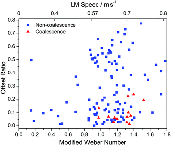
Fig. 7 presents the outcomes of multiple LM collisions, with non-coalescing collisions shown as blue squares, and coalescing collisions shown as red triangles. The modified Weber number, We*, has been plotted against the offset ratio, X* – which ranges from 0 (a direct hit) to 1 (a near miss). Also portrayed, for readers convenience, is the LM speed which (for LMs of the same coating and size) is directly related to the modified Weber number.
It can be seen from the results in Fig. 7 that no speed exists for which the probability of coalescence between two colliding LM is 100%. Instead, a small range between a We* of 1.0 to 1.4 and an offset ratio of 0.0 to 0.1, arise as the most likely conditions for LM coalescence. The lack of LM coalescence below a We* of 1.0 was expected, as this is the point where the kinetic energy of the approaching LM exceeds the LM surface tension, i.e. Ek > Es.
It is interesting to note that there were multiple collisions with We* > 1.4 that did not result in coalescence. This implies that there is a variability that has not been adequately accounted for – most likely the particle coating on the surface of the LM. It is probable that the more robust LMs have either a more efficient surface packing, or a larger than typical number of layers (n). Although the generation of LMs was standardised with drop height, number of rolls, etc., unavoidable variations in the particle coating were occasionally observed. It also noteworthy that throughout the experiments, a small amount of powder was observed leaving the LMs – both during rolling and collisions. This particle-loss, though non-zero, was considered to be minimal.
It was observed that, when ν > 0.6 m s−1 (We* > 0.96), the mobile LM deformed into an unusual shape. This LM deformation, shown in Fig. 8, has not been reported previously to the authors’ knowledge. The front of the deformed LM has a breadth of 2.5 mm, the ‘tail’ has a breadth of 1.4 mm, and it has an overall length of 7.5 mm. The deformation is thought to be caused by the bulk of the water accelerating faster than the powder coating can roll. This creates elongation as the powder causes drag on the LM, due to the friction coefficient between PE and the surface (PLA) creating a barrier to sliding. It is worthy of note that all of the observed coalescence events also occur above this threshold (We* > 0.96), suggesting that the deformation could be linked to coalescence rate. Deviation from an idealised sphere shape will stretch the powder coating over a larger area, resulting in either a thinner coating or gaps. Either of which would be expected to increase coalescence prevalence.
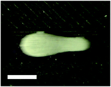 | ||
| Fig. 8 A deformed 15 μL PE LM is moving from the right of the image to the left. It has a velocity of 0.63 m s−1 and an overall length of 7.5 mm. The scale bar is 3 mm. | ||
3.6 Volume dependence of liquid marble coalescence
It was noted that with the experimental apparatus presented in this work, smaller LMs (<15 μL) were unable to coalesce reliably. In an attempt to improve the rate of coalescence, the speed of the mobile LMs (and thereby their kinetic energy) was increased through step-wise increases in the ramp height. This had the unintentional side effect of the LMs separating from the ramp during descent, before colliding with the bottom of the ramp. The majority of these LMs did not survive this large initial drop, breaking up upon impact. Premature LM death was avoided by redesigning the vertical section of the ramp to have an incline of 5°. This permitted the LMs to roll down the ramp without damage and collide with the stationary LMs as intended. The ramp was extended several times until the LMs attained terminal velocity. Even at maximum velocity, LM collisions did not result in coalescence, regardless of offset value. The absence of coalescent collisions, irrespective of LM velocity, offset value, and modified Weber number, can be observed clearly in the graph provided in the ESI,† which depicts the results of impacts between 10.0 μL LMs.Nonetheless, coalescence of small (11.6 μL) LMs has been previously reported by this team during free rolling collisions between two mobile LMs.19 During our previous study, it was possible to tune such collisions to initiate coalescence by variation of the powder coating and impact velocity. This suggests that the use of a less robust powder coating may allow for static-mobile coalescence.
The lack of coalescing collisions was similarly encountered for LMs larger than 15 μL. It is known that larger LMs do not roll faster, but actually slower due to the increased deformation of the LM surface resulting in a greater contact area between the substrate surface and the LM, which causes an increase in friction.2,46 The kinetic energy of a moving object is dependent on the square of its velocity, consequently the impact energy is greatly reduced for larger, slower, LMs. A reduced impact energy would be unable to overcome the surface energy, explaining the observed lack of coalescence.
3.7 Grain size dependence of liquid marble coalescence
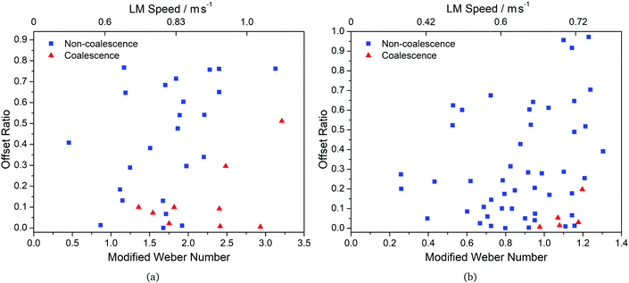
In order to determine the effect of the PE particle (or grain) size present in the LM powder coating on the coalescence parameters, LMs were coated with PE particles of a controlled size. The size of the PE particles was controlled by sieving the PE powder in order to isolate particles within a narrow diameter range. LMs were thus made using PE powder with two grain size distributions: 63 μm to 90 μm, and 180 μm to 250 μm. The collisions of these marbles were investigated through the experimental protocol previously described in this paper.LMs made using the smaller grain size (63 μm to 90 μm) were able to achieve faster accelerations, with respect to LMs with uncontrolled PE grain size, without breaking apart. As such it was possible to achieve collisions at much greater velocities and, consequently, larger modified Weber numbers than those previously observed in LMs with uncontrolled PE coatings. The outcomes of these collisions can be seen in Fig. 9a. The window for successful coalescence was much larger than for LMs with a mixed grain size, with coalescence observed for We* > 1.5 and offset ratios as large as X* < 0.5. The observed large coalescence window can be attributed to two main factors; larger modified Weber numbers available to the LMs before structural failure, and the smaller PE grain size. The PE grain size is likely to have had an impact, as for coalescence to occur the water in the LM core needs to traverse the hydrophobic gaps between the particles of the powder coating. If this gap is minimised (due to a smaller grain size), then a lower energy is required to traverse it, thus increasing the ease of coalescence.
It was also observed that, compared to LMs made with a mixed grain size, the LMs made with a small grain size decelerated much more slowly once on the level section of the ramp. This effect is attributed to a smoother profile on the LM surface, which reduces the rolling resistance of the LM. Conversely, LMs made using the larger grain size (180 μm to 250 μm) were found to have similar acceleration and deceleration rates as the mixed grain size PE LMs. This implies that it is the larger particles on the surface of the LM that have the biggest influence on its velocity. Indeed, larger particles have a larger spacing between maxima which results in a more rugged LM surface (and thereby a higher rolling resistance).
The outcomes of the collisions between LMs made using the larger grain size (180 μm to 250 μm) are shown in Fig. 9b. It can be seen that the window for coalescence collisions is comparable with that of LMs made with mixed grain size PE. As with the LM velocity, this suggests that it is the largest grain size in the LM powder coating that dominates LM coalescence parameters. The larger particles mean that the water core has a greater area of hydrophobicity to traverse before making contact with the core of the collided LM, resulting in an increase in the energy required for coalescence.
Whilst the larger grain size LMs had comparable coalescence parameters to the mixed grain-size LMs, they were not as robust during mechanical manipulations. Both the small and large grain-size LMs were notably less resilient than the mixed grain-size LMs. We suggest that in LMs with mixed grain sizes, the small particles hole-fill in the gaps left by the larger particles (essentially unequal sphere packing47). This packing allows the LMs to temporarily deform away from an idealised sphere without exposing the additional surface area which is created. This is possible because the smaller particles, previously held within the interstices of the larger particles, are able to disperse across and coat the newly exposed surface of the deformed LM. This flexible coating effectively increases the robustness and resilience to knocks of LMs with a mixed grain size powder coating.
3.8 Water droplet collisions
A separate, identical, collision ramp was made superhydrophobic using a commercial hydrophobic spray (Rust-Oleum NeverWet), in order to observe how naked water droplets would behave under similar conditions. Water droplets (15 μL) were pipetted at the top of the ramp using an air displacement micropipette. The droplet was then encouraged to roll down the ramp using a gentle air flow from a disposable plastic Pasteur pipette.It was observed that the water droplets moved with a much higher velocity than their LM counterparts, with typical speeds at the bottom of the ramp in the region of 1 m s−1 compared to a typical speed of 0.6 m s−1 for PE coated LMs of the same volume. This can be explained by the different frictional forces enacting on the two species. LMs have a rugged surface due to the powder coating, whilst a naked water droplet has a comparably smooth surface. It follows that the species with the smoother surface would accelerate quicker and have a higher maximum velocity, all other things being equal. Indeed, it is known that the acceleration of a LM decreased as its volume increases,2 which is the opposite to a naked water droplet48 – in line with a dramatic increase in friction for the LM as the surface contact area increases. Interestingly, it has been demonstrated that while small naked water droplets have a lower velocity than larger droplets, they also have a greater rotational speed.48 This suggests that there may be an element of sliding and/or slipping involved – though such an element is likely to be minimal, as the motion of a naked water droplet on a hydrophobic surface is known to be primarily composed of rolling (as opposed to sliding).48–50 An additional limitation on the free movement of LMs is static build-up, as previously reported.12 This would also have been a contributory factor in the observed discrepancy between the two species’ accelerations.
As the mobile and stationary water droplets made contact, they coalesced. This can be seen in Fig. 10. During the combination, the forward direction of movement continued, with a decreased velocity (from 1.2 m s−1 to 0.6 m s−1), indicative of an inelastic collision. Oscillations within the newly formed larger droplet began immediately upon coalescence, with a frequency of approximately 35 Hz. The oscillations started perpendicular to the direction of impact, and alternated with the direction of impact. These observations are consistent with those previously reported for bare water droplet collisions.51
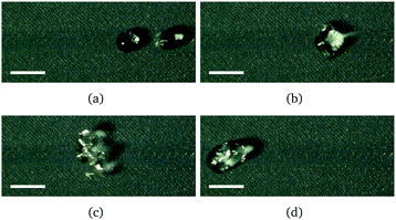 | ||
| Fig. 10 An example coalescing collision of two water droplets. Respective time differences from frame (a) are (a) 0 ms, (b) 5 ms, (c) 16 ms, and (d) 32 ms. The mobile droplet is approaching from the right. The scale bars are 5 mm. The video is available in the ESI.† | ||
In our experiments, all naked water droplet impacts resulted in coalescence, regardless of modified Weber number (experimental range 4.8 < We* < 7.9; X* = 0). The modified Weber number is larger than for similarly sized LMs because the differences in velocity, surface tension and density all increase Weber number. Rebounding naked water droplets with a volume of approximately 14 μL have been previously reported.52 In such cases, both We* and X* had to be controlled – for an offset ratio of 0, the rebound range was reported to be approximately 1.75 < We* < 5.
It is interesting to note that, despite the comparable increase in both Weber number and velocity, the water droplets do not deform whilst rolling in either the same manner or to the same extent observed for LMs. This reinforces the suggestion that the coating of the LMs causes their deformation via the additional drag induced by the noted link between the translational and rotational motions of accelerating LMs (whilst their energy is lower than the frictional forces imparted by the powder coating).
3.9 Comparisons with vertical collision studies
Caution should be taken with the direct comparison of these results with other coalescence investigations, due to the inherent variations caused by different powder coatings. That said, with care, some interesting observations can be made. Firstly, in both of the studies by Planchette et al.17 and Jin et al.,18 it was noticed that smaller LMs are harder to coalesce than larger LMs. This was also noted in our study. Comparatively, both groups also reported that the ease of coalescence increased as the LM volume increased. We did not observe this, finding that larger LMs lacked the velocity to initiate coalescence. It is likely that the vertically free-falling LMs achieved greater acceleration than our rolling LMs, due to a lack of surface friction. We did however find that an increase in collision velocity resulted in an increase in coalescence likelihood, as also noted by Planchette et al. and Jin et al.An interesting variation can be found between our results and those of Jin et al. when considering the offset ratio.18 We found that head on collisions provided the highest coalescence rate. They reported however, that whilst most LMs had a preferred coalescence offset ratio of 0, smaller LMs had a higher coalescence probability when X* = 0.4. They explained this phenomenon as an effect of shear forces, not applicable for larger LMs. The same interpretation explains why we did not observe this trait: our stationary LMs were able to freely roll away from the collision, preventing the build up of said force.
There is also a variation in the magnitude of the modified Weber number needed to initiate coalescence. Jin et al. reported that We* > 0.6 was necessary for coalescence,18 whilst we observed that coalescence required We* ≥ 0.97 in all recorded cases. This additional energy requirement is not surprising, as in our freestanding collisions the stationary LM is able to roll away from the collision on impact, thereby dissipating some of the incoming energy. It follows that additional energy would be needed to compensate for this loss.
Finally, our investigations revealed that naked water droplets coalesce more easily than LMs of comparable volume. The same observations were also made by Planchette et al.17 This indicates that the hydrophobic barrier instigated by the powder coating of the LM (and absent in a naked droplet) requires a non-negligible amount of energy to overcome – as anticipated.
4 Application to computing
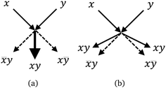
Collision-based computing53 uses the interactions and collisions between objects to perform logic functions. In general, a single object continues on its path unabated; whilst the presence of a second object causes a change in direction and/or mass. This change is then interpreted as a logic function, and more generally as computing. Such gates have been demonstrated with many mediums, including billiard balls,54,55 vesicles,56 and liquid marbles.19 The use of LMs has many unique properties and advantages in such systems: they have a low hysteresis, and so are easy to propel; they are highly tunable, due to the large variety of cores and powder coatings that can be utilised; they can be loaded with ‘cargo’, indeed they can be conveniently opened and closed at either acoustically22 or magnetically for loading & unloading purposes;57 coalescence of colliding LMs can be exploited to initiate chemical reactions;16 simple control of dimensions is provided by varying the water droplet volume, even after formation; it is possible to both combine and divide the LMs (i.e. signals) at will;58 and when the LM is no longer required, both the core and the coating can be easily reused in future LMs.The coalescence of two LMs implements gate 〈x,y〉 → 〈![[x with combining macron]](https://www.rsc.org/images/entities/i_char_0078_0304.gif) y,xy,xȳ〉 (Fig. 11a) and bouncing implements 〈x,y〉 → 〈xy,
y,xy,xȳ〉 (Fig. 11a) and bouncing implements 〈x,y〉 → 〈xy,![[x with combining macron]](https://www.rsc.org/images/entities/i_char_0078_0304.gif) y,xȳ,xy〉 (Fig. 11b). In such gates, the LM is considered to be the signal or signal carrier. In a framework of collision-based computing, coalescence based gates are potentially less useful because the mass of the signal carriers doubles after each and gate operation. This inevitably leads to the requirement of an auxiliary ‘signal divider’, in order to maintain the original signal mass and prevent exponential growth of said mass.
y,xȳ,xy〉 (Fig. 11b). In such gates, the LM is considered to be the signal or signal carrier. In a framework of collision-based computing, coalescence based gates are potentially less useful because the mass of the signal carriers doubles after each and gate operation. This inevitably leads to the requirement of an auxiliary ‘signal divider’, in order to maintain the original signal mass and prevent exponential growth of said mass.
However, coalescence based gates might be advantageous in non-traditional collision-based computing, where logical values are encoded not into presence/absence of a LM, but in concentrations of chemical species in the LMs cargo. Nevertheless, whether coalescence or non-coalescence gates are implemented, being able to control and fine-tune the coalescence probability is critical.
5 Conclusions
In the present study, the optimal coalescence conditions between a static and a mobile LM with an aqueous core and a PE coating were determined, through repeated collisions at a variety of offset ratios, modified Weber numbers, and velocities. It was shown that for a PE LM with a volume of 15 μL at optimal collision conditions (1.0 < We* < 1.4 and 0.0 < X* < 0.1), the occurrence of coalescence was no greater than 50%. This result demonstrates that coalescence between a static and a moving LM is a significantly less reliable process than that of coalescence between two moving LMs. Furthermore, it was observed that in collisions between a static and a mobile LM, the non-coalescence window is much larger with a higher probability: zero coalescence was observed when X* > 0.25, or when We* < 0.95 or We* > 1.55.It is suspected that the low coalescence probability observed in the studied collisions arises from the variability in the PE powder coating of the LMs. This was demonstrated by studies on the grain size of the LM powder coating which revealed that smaller grain sizes permitted more facile coalescence. However, it was also observed that LMs made using monodisperse particles were generally less mechanically robust than LMs made using mixed grain sizes.
Comparisons were also made between the outcome of collisions of equally sized LMs, with volumes both smaller and larger than 15 μL. It was determined that the low modified Weber number achieved with 10 μL LMs, due to their fragile nature at higher speeds, was insufficient to initiate coalescence; whilst larger LMs were unable to obtain sufficient velocity for coalescence, due to their greater rolling resistance.
These results will further enhance the applicability of LMs in a wide variety of applications by facilitating controlled outcomes of LM collisions. In order to further improve control over LM coalescence, the effects of both the LM core and powder coating are being actively studied. Further work is also being performed on the deformations of fast moving LMs in order to fully understand (and take advantage of) the novel geometry observed in this study, and as to whether the high-speed deformation of LMs can be exploited for coalescence-control.
Conflicts of interest
There are no conflicts of interest to declare.Acknowledgements
The authors thank Dr David Patton for his help with SEM imaging. This research was supported by the EPSRC with grant EP/P016677/1.References
- N. Pike, D. Richard, W. Foster and L. Mahadevan, Proc. R. Soc. B, 2002, 269, 1211–1215 CrossRef PubMed.
- P. Aussillous and D. Quéré, Nature, 2001, 411, 924–927 CrossRef CAS PubMed.
- E. Bormashenko, Y. Bormashenko, A. Musin and Z. Barkay, ChemPhysChem, 2009, 10, 654–656 CrossRef CAS PubMed.
- P. Aussillous and D. Quéré, Proc. R. Soc. A, 2006, 462, 973–999 CrossRef CAS.
- C. H. Ooi, A. van Nguyen, G. M. Evans, O. Gendelman, E. Bormashenko and N.-T. Nguyen, RSC Adv., 2015, 5, 101006–101012 RSC.
- G. McHale and M. I. Newton, Soft Matter, 2015, 11, 2530–2546 RSC.
- Y. Zhang and N.-T. Nguyen, Lab Chip, 2017, 17, 994–1008 RSC.
- E. Bormashenko, Langmuir, 2017, 33, 663–669 CrossRef CAS PubMed.
- C. Fullarton, T. C. Draper, N. Phillips, B. P. J. de Lacy Costello and A. Adamatzky, J. Phys.: Mater., 2019, 2, 015005 Search PubMed.
- N. M. Oliveira, R. L. Reis and J. F. Mano, Adv. Healthcare Mater., 2017, 6, 1700192 CrossRef PubMed.
- T. C. Draper, C. Fullarton, N. Phillips, B. P. J. de Lacy Costello and A. Adamatzky, Sci. Rep., 2018, 8, 14153 CrossRef PubMed.
- C. Fullarton, T. C. Draper, N. Phillips, R. Mayne, B. P. J. de Lacy Costello and A. Adamatzky, Langmuir, 2018, 34, 2573–2580 CrossRef CAS PubMed.
- J. Tian, T. Arbatan, X. Li and W. Shen, Chem. Commun., 2010, 46, 4734 RSC.
- E. Bormashenko, R. Pogreb, R. Balter, H. Aharoni, Y. Bormashenko, R. Grynyov, L. Mashkevych, D. Aurbach and O. Gendelman, Colloid Polym. Sci., 2015, 293, 2157–2164 CrossRef CAS.
- P. S. Bhosale and M. V. Panchagnula, Langmuir, 2012, 28, 14860–14866 CrossRef CAS PubMed.
- Z. Chen, D. Zang, L. Zhao, M. Qu, X. Li, X. Li, L. Li and X. Geng, Langmuir, 2017, 33, 6232–6239 CrossRef CAS.
- C. Planchette, A.-L. Biance, O. Pitois and E. Lorenceau, Phys. Fluids, 2013, 25, 042104 CrossRef.
- J. Jin, C. H. Ooi, D. V. Dao and N.-T. Nguyen, Soft Matter, 2018, 14, 4160–4168 RSC.
- T. C. Draper, C. Fullarton, N. Phillips, B. P. de Lacy Costello and A. Adamatzky, Mater. Today, 2017, 20, 561–568 CrossRef CAS.
- Y. Zhao, Z. Xu, M. Parhizkar, J. Fang, X. Wang and T. Lin, Microfluid. Nanofluid., 2012, 13, 555–564 CrossRef CAS.
- Y. Zhao, H. Gu, Z. Xie, H. C. Shum, B. Wang and Z. Gu, J. Am. Chem. Soc., 2013, 135, 54–57 CrossRef CAS PubMed.
- D. Zang, J. Li, Z. Chen, Z. Zhai, X. Geng and B. P. Binks, Langmuir, 2015, 31, 11502–11507 CrossRef CAS PubMed.
- Z. Liu, X. Fu, B. P. Binks and H. C. Shum, Soft Matter, 2017, 13, 119–124 RSC.
- J. Jin, C. Ooi, D. Dao and N.-T. Nguyen, Micromachines, 2017, 8, 336 CrossRef PubMed.
- M. Frenkel, L. Dombrovsky, V. Multanen, V. Danchuk, I. Legchenkova, S. Shoval, Y. Bormashenko, B. P. Binks and E. Bormashenko, J. Phys. Chem. B, 2018, 122, 7936–7942 CrossRef CAS.
- M. Paven, H. Mayama, T. Sekido, H.-J. Butt, Y. Nakamura and S. Fujii, Adv. Funct. Mater., 2016, 26, 3199–3206 CrossRef CAS.
- N. Kavokine, M. Anyfantakis, M. Morel, S. Rudiuk, T. Bickel and D. Baigl, Angew. Chem., Int. Ed., 2016, 55, 11183–11187 CrossRef CAS.
- N.-T. Nguyen, M. Hejazian, C. Ooi and N. Kashaninejad, Micromachines, 2017, 8, 186 CrossRef.
- F. N. Ajjan, M. Ambrogi, G. A. Tiruye, D. Cordella, A. M. Fernandes, K. Grygiel, M. Isik, N. Patil, L. Porcarelli, G. Rocasalbas, G. Vendramientto, E. Zeglio, M. Antonietti, C. Detrembleur, O. Inganäs, C. Jérôme, R. Marcilla, D. Mecerreyes, M. Moreno, D. Taton, N. Solin and J. Yuan, Polym. Int., 2017, 66, 1119–1128 CrossRef CAS.
- E. Bormashenko, A. Musin, G. Whyman, Z. Barkay, A. Starostin, V. Valtsifer and V. Strelnikov, Colloids Surf., A, 2013, 425, 15–23 CrossRef CAS.
- T. Arbatan and W. Shen, Langmuir, 2011, 27, 12923–12929 CrossRef CAS.
- C. H. Ooi, C. Plackowski, A. V. Nguyen, R. K. Vadivelu, J. A. St. John, D. V. Dao and N.-T. Nguyen, Sci. Rep., 2016, 6, 21777 CrossRef CAS.
- F. Celestini and E. Bormashenko, J. Colloid Interface Sci., 2018, 532, 32–36 CrossRef CAS PubMed.
- D. Zang, Z. Chen, Y. Zhang, K. Lin, X. Geng and B. P. Binks, Soft Matter, 2013, 9, 5067–5073 RSC.
- E. Bormashenko, R. Pogreb, G. Whyman and A. Musin, Colloids Surf., A, 2009, 351, 78–82 CrossRef CAS.
- C. H. Ooi, E. Bormashenko, A. V. Nguyen, G. M. Evans, D. V. Dao and N.-T. Nguyen, Langmuir, 2016, 32, 6097–6104 CrossRef CAS PubMed.
- E. Bormashenko, G. Whyman and O. Gendelman, Adv. Condens. Matter Phys., 2015, 2015, 1–6 CrossRef.
- T. Matsumoto, T. Nakano, H. Fujii, M. Kamai and K. Nogi, Phys. Rev. E: Stat., Nonlinear, Soft Matter Phys., 2002, 65, 031201 CrossRef CAS PubMed.
- X. Li, R. Wang, H. Shi and B. Song, Appl. Phys. Lett., 2018, 113, 101602 CrossRef.
- E. Bormashenko, R. Pogreb, G. Whyman, A. Musin, Y. Bormashenko and Z. Barkay, Langmuir, 2009, 25, 1893–1896 CrossRef CAS PubMed.
- T. Supakar, A. Kumar and J. O. Marston, Phys. Rev. E, 2017, 95, 013106 CrossRef CAS PubMed.
- C. H. Ooi, R. K. Vadivelu, J. St. John, D. V. Dao and N.-T. Nguyen, Soft Matter, 2015, 11, 4576–4583 RSC.
- D. Matsukuma, H. Watanabe, A. Fujimoto, K. Uesugi, A. Takeuchi, Y. Suzuki, H. Jinnai and A. Takahara, Bull. Chem. Soc. Jpn., 2015, 88, 84–88 CrossRef CAS.
- T. C. Draper, C. Fullarton, N. Phillips, B. P. J. de Lacy Costello and A. Adamatzky, in UCNC 2018, LNCS 10867, ed. S. Stepney and S. Verlan, Springer, 2018, pp. 59–71 Search PubMed.
- J. Liu and P. Zuo, Eur. Phys. J. E: Soft Matter Biol. Phys., 2016, 39, 17 CrossRef PubMed.
- L. Mahadevan and Y. Pomeau, Phys. Fluids, 1999, 11, 2449–2453 CrossRef CAS.
- D. R. Hudson, J. Appl. Phys., 1949, 20, 154–162 CrossRef CAS.
- B. S. Yilbas, A. Al-Sharafi, H. Ali and N. Al-Aqeeli, RSC Adv., 2017, 7, 48806–48818 RSC.
- S. P. Thampi, R. Adhikari and R. Govindarajan, Langmuir, 2013, 29, 3339–3346 CrossRef CAS PubMed.
- N. Gao, F. Geyer, D. W. Pilat, S. Wooh, D. Vollmer, H.-J. Butt and R. Berger, Nat. Phys., 2017, 14, 191–196 Search PubMed.
- N. Ashgriz and J. Y. Poo, J. Fluid Mech., 1990, 221, 183–204 CrossRef CAS.
- H. Mertaniemi, R. Forchheimer, O. Ikkala and R. H. A. Ras, Adv. Mater., 2012, 24, 5738–5743 CrossRef CAS PubMed.
- Collision-Based Computing, ed. A. Adamatzky, Springer, London, 2002 Search PubMed.
- E. Fredkin and T. Toffoli, Collision-based computing, Springer, 2002, pp. 47–81 Search PubMed.
- T. Toffoli, International Colloquium on Automata, Languages, and Programming, 1980, pp. 632–644 Search PubMed.
- R. Mayne and A. Adamatzky, PLoS One, 2015, 10, e0139617 CrossRef PubMed.
- Y. Zhao, J. Fang, H. Wang, X. Wang and T. Lin, Adv. Mater., 2010, 22, 707–710 CrossRef CAS PubMed.
- E. Bormashenko and Y. Bormashenko, Langmuir, 2011, 27, 3266–3270 CrossRef CAS PubMed.
Footnote |
| † Electronic supplementary information (ESI) available. See DOI: 10.1039/c9sm00328b |
| This journal is © The Royal Society of Chemistry 2019 |

