 Open Access Article
Porous g-C3N4 covered MOF-derived nanocarbon materials for high-performance supercapacitors†
Chao Lu a and
Xi Chen
 *ab
*ab
aDepartment of Earth and Environmental Engineering, Columbia University, New York, NY 10027, USA. E-mail: xichen@columbia.edu
bSchool of Chemical Engineering, Northwest University, Xi'an 710069, China
First published on 28th November 2019
Abstract
Supercapacitors with high power density and long cycle life have shown great potential in energy storage supply for modern electronic devices. Among the component parts of supercapacitors, electrode materials with high electrical conductivity, large surface area and porosity are critical to the energy storage performances of devices. Here, we report a porous g-C3N4 covered MOF-derived nanocarbon material with large specific surface area and high nitrogen doping level as an electrode material for supercapacitors. The large surface area provides high capacity for ion accommodation during electrochemical processes, and the high nitrogen doping facilitates electron and ion transport with extra pseudocapacitance. The supercapacitor based on the as-synthesized material delivers a high specific capacity of 106 F g−1 at current density of 1 A g−1 as well as good rate capability. Furthermore, the device presents good cycling stability with capacitance retention of 91% even after 10![[thin space (1/6-em)]](https://www.rsc.org/images/entities/char_2009.gif) 000 cycles at 1 A g−1 under 0.8 V. This study presents a new insight into the design of nanocomposite materials with high energy storage capability and will accelerate the practical application of supercapacitors in future.
000 cycles at 1 A g−1 under 0.8 V. This study presents a new insight into the design of nanocomposite materials with high energy storage capability and will accelerate the practical application of supercapacitors in future.
1. Introduction
Supercapacitors have presented attractive choices for electronic equipment nowadays because of their high power density, fast charging speed, scalability, and long cycling life.1,2 Compared with electrolyte materials, electrochemical performances of supercapacitors are mainly determined by the properties of the electrode materials.3,4 On the one hand, the large specific surface area of electrode materials will improve ion accommodation capability and thus increase energy storage capacity of supercapacitors.5,6 On the other hand, electronic structure regulation of electrode materials through doping methods has been proved to be effective for enhancement of ion and electron kinetics in supercapacitors.7,8 Thus, it is promising to develop novel structural materials with large specific surface area and heteroatom doping structures for achieving higher energy storage capacity.Metal–organic frameworks (MOFs) derived nanocarbon materials have attracted great attention in energy storage owing to the high surface area and porous structure.9,10 But the MOF-derived materials are normally nanoparticles with discontinuous structure and this will lead to the insufficient contact area of nanoparticles. It will absolutely result in inferior electronic conductivity of electrodes and thus with unfavorable energy storage properties of supercapacitors.11,12 Constructing continuous conductive path for MOF-derived carbon materials, such as covering the discrete nanoparticles with two-dimensional materials, are believed to be effective method for addressing this issue. Graphic carbon nitride (g-C3N4) material with two-dimensional structure is an ideal candidate for introducing this kind of conductive path because of the high nitrogen doping level, controllable electronic structure and confinement effect.13,14 Thus, integration of the two materials into nanocomposite seems to be a good strategy for fabrication of high energy-density electrode materials.
Here, we report a porous g-C3N4 covered MOF-derived nanocarbon materials (PMGCN) with large specific surface area and high nitrogen doping level as electrode materials for supercapacitors. The large surface area provides enough space for ion accommodation during charge–discharge processes, and high nitrogen doping facilitates electrons and ions transport through pseudocapacitive behavior. The PMGCN material based supercapacitor gives high specific capacity of 106 F g−1 at current density of 1 A g−1 as well as good rate capability at 10 A g−1. It exhibits good air-working stability with capacitance retention of 91% after 10![[thin space (1/6-em)]](https://www.rsc.org/images/entities/char_2009.gif) 000 cycles at 1 A g−1 under 0.8 V. This work presents a simple but effective strategy of material engineering and will accelerate development of energy storage devices.
000 cycles at 1 A g−1 under 0.8 V. This work presents a simple but effective strategy of material engineering and will accelerate development of energy storage devices.
2. Experimental section
2.1 Materials
Melamine, polyvinyl alcohol (PVA), polyvinylidene fluoride (PVdF) and zinc nitrate (Zn(NO3)2) were bought from Sigma-Aldrich Inc. 2-Methylimidazole, nitric acid, sulfuric acid (H2SO4), dimethyl formamide (DMF), and methanol were obtained from Aladdin Reagent Co., Ltd. deionized water was homemade.2.2 Synthesis of g-C3N4 material
Firstly, 5 g melamine was placed into crucible after drying at 80 °C for 24 h. Secondly, the crucible was heated to 550 °C for 3 h with heating rate of 3 °C min−1. After cooling down, the material was washed with 2 M nitric acid solution and deionized water for 3 times and then heated to 600 °C for 3 h at rate of 5 °C min−1. Subsequently, the g-C3N4 material was obtained after washing with nitric acid and deionized water for 3 times. Finally, the g-C3N4 material was got under vacuum condition at 90 °C for 24 h.2.3 Synthesis of PMGCN nanocomposite
Firstly, 0.3 g Zn(NO3)2 was dissolved in 100 mL methanol and stirred for 1 h to form solution A. Subsequently, 0.6 g 2-methylimidazole was dissolved in 100 mL methanol to form solution B that was added dropwise to solution A with stirring. After stirring for 60 min, the reaction was aged at 25 °C without any disturbance for 24 h. Then, the white precipitate was collected by washing with methanol before vacuum drying at 70 °C overnight. Subsequently, the ZIF-8 powder was transferred into crucible and heated to 800 °C for 3 h with rate of 5 °C min−1 under argon atmosphere. After that, the obtained MOF-derived carbon material (0.1 g) was dispersed with g-C3N4 material (0.1 g) in DMF under ultrasonification for 2 h. Finally, the PMGCN nanocomposite was obtained after filtration, washing and vacuum drying.2.4 Fabrication of all-solid-state supercapacitor
Firstly, 0.5 g PMGCN, 0.05 g carbon black and 0.05 g PVdF were dissolved in 100 mL of N,N-dimethyl formamide through sonication. Then, the solution was poured onto mould and dried at 85 °C for 24 h for obtaining electrode membrane. Subsequently, 1.0 g PVA and 0.1 g H2SO4 were dissolved in deionized water and prepared into electrolyte membrane through casting method above. Lastly, the all-solid-state supercapacitor was obtained by assembling graphene electrodes with PVA/H2SO4 electrolyte.2.5 Material characterizations
SEM and TEM characterisations were measured by Zeiss SIGMA VP and FEI Tecnai G2 F20 equipments. X-ray powder diffraction analysis was made by Philips X'Pert PRO machine using nickel-filtered Cu Kα radiation. X-ray photoelectron spectra was conducted by PHI 5000 VersaProbe II instrument. Nitrogen adsorption analysis was measured with Micromeritics ASAP 2020 machine based on Brunauer–Emmett–Teller method.2.6 Electrochemical measurement
Electrochemical performances of supercapacitor were measured through Bio-logic Potentiostat VMP3 work station. CV curves were measured in the potential range of 0–0.8 V with scan rates from 5 to 100 mV s−1. Electrochemical impedance spectroscopy was conducted from 10 mHz to 100 kHz with a voltage amplitude of 10 mV. Galvanostatic charge–discharge measurements were conducted from 1 to 10 A g−1 under voltage of 0.8 V. The specific capacitance of the device was calculated at various current densities through the following formula.where I (A) is discharge current, ΔV (V) refers to the potential change within the discharge time Δt (s), and m (g) represents active material weight in device.
3. Results and discussion
3.1 Synthesis procedure of PMGCN nanocomposite
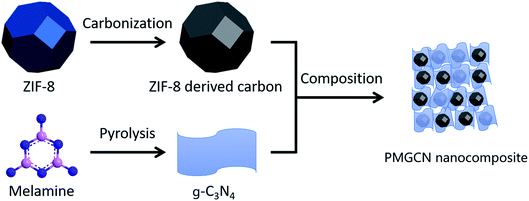
Synthesis procedures of PMGCN nanocomposite are briefly illustrated in Fig. 1 and the experimental details are presented in the Experimental section. Typically, g-C3N4 material was prepared through pyrolysis of melamine monomer. The pyrolysis of melamine was conducted under ambient pressure with pyrolysis-generated self-supporting atmosphere, which has been reported by previous studies.15,16 In this experiment, zeolitic imidazolate frameworks-8 (ZIF-8), a kind of common MOFs, was selected as pyrolysis precursor because of its good thermal stability, which guarantees the intact structure after pyrolysis treatment without serious structure collapse.17–19 Subsequently, MOF-derived nanocarbon materials were obtained after carbonization with designed temperature program under argon atmosphere. After that, the final nanocomposite was obtained through by ultrasonic composition of the two materials. The optical images of g-C3N4 and PMGCN materials were shown in Fig. S1, ESI.†3.2 Morphological analysis of PMGCN nanocomposite
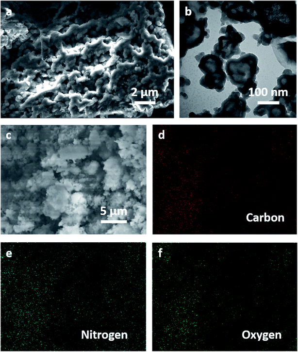
SEM and TEM characterizations were employed to investigate morphology of PMGCN material, as shown in Fig. 2. SEM image of PMGCN material in Fig. 2a indicates the MOF-derived carbon material was uniformly covered by g-C3N4 materials, which is beneficial for forming conductive path in the electrode material. TEM image of the material at higher resolution shows the good retention of nanoparticle morphology without obvious structural collapse. From energy dispersive X-ray spectrometry (EDX) elemental mappings in Fig. 2c–f, it can be concluded that large amounts of N atoms are uniformly distributed in PMGCN material. The morphology results directly clarify the good composite structure of the two materials and the combination of these structural advantages will promote energy storage performances of the PMGCN material. The SEM images of g-C3N4 and ZIF-8 materials are displayed for comparison in Fig. S2 and S3, ESI.† | ||
| Fig. 2 Morphology of PMGCN nanocomposite. (a and b) SEM and TEM images of PMGCN material. (c–f) Scanning SEM image and EDX mappings of carbon, nitrogen and oxygen element, respectively. | ||
3.3 Structural characteristics of PMGCN nanocomposite
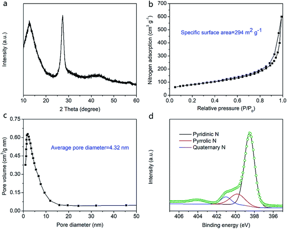
In order to verify structural characteristics of PMGCN nanocomposite, X-ray diffraction (XRD) pattern, nitrogen (N2) adsorption/desorption isotherm, and X-ray photoelectron spectroscopy (XPS) were conducted in Fig. 3. There exist two distinct diffraction peaks in Fig. 3a, which can be attributed to graphitic structure of the nanomaterial.20,21 As we known, specific surface area and pore diameter are crucial to electrochemical performances of electrode materials. Specific surface area and pore characteristics of PMGCN materials were clearly examined by N2 adsorption/desorption isotherm. According to the result in Fig. 3b, PMGCN materials show high specific surface area of 294 m2 g−1, which will improve its ion accommodation capability. As displayed in Fig. 3c, average pore diameter of the material is about 4.32 nm, which is believed in optimal range for rapid ion transport.22 From the XPS result in Fig. 3d, the N 1s signal can be fitted into three subpeaks, corresponding to pyridinic N, pyrrolic N, and quaternary N, respectively. Pyridinic N and pyrrolic N are good for pseudocapacitance while quaternary N is beneficial for enhancement of electrical conductivity of electrode.23,24 | ||
| Fig. 3 Chemical structure characterizations of PMGCN nanocomposite. (a) XRD pattern. (b) N2 adsorption/desorption isotherm. (c) Pore diameter distribution. (d) XPS scans for N 1s spectra analysis. | ||
3.4 Electrochemical performances of supercapacitors
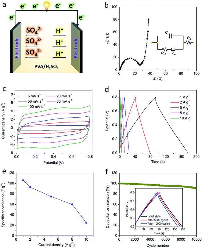
To verify potential of PMGCN material as electrode of supercapacitor, an all-solid-state supercapacitor was prepared by assembling the electrode material with PVA/H2SO4 electrolyte. Schematic for device structure and working mechanism is shown in Fig. 4a. Preparation process of PMGCN material based electrodes is displayed in Fig. S4, ESI.† Electrochemical impedance (EIS) plot for the supercapacitor is displayed in Fig. 4b and the corresponding equivalent circuit diagram is shown in the inset. The equivalent series resistance is 26.6 ohm, showing good interfacial contact in the device. Based on cyclic voltammograms (CV) curves in Fig. 4c, the rectangular shapes with slight disorder under different scan rates demonstrate capacitive mechanism with some pseudocapacitive behavior. The pseudocapacitive effect is caused by nitrogen doping in the electrode material and thus increases specific capacity of the device.25 Charge–discharge (CD) curves of the device are conducted at various current densities in Fig. 4d for clarifying the specific capacitance, whose triangular shapes indicate the high coulombic efficiency. It is observed that specific capacitance exhibits 106 F g−1 at current density of 1 A g−1 and remains as high as 20 F g−1 at the high current density of 10 A g−1. These superior results imply that PMGCN material based device achieves high energy capacity with good rate capability. Notably, this device presents excellent air cycling stability over 10![[thin space (1/6-em)]](https://www.rsc.org/images/entities/char_2009.gif) 000 times in Fig. 4f, showing great potential for practical applications.
000 times in Fig. 4f, showing great potential for practical applications.
4. Conclusion
In summary, a PMGCN nanocomposite was designed as electrode materials for high-performance supercapacitors. This material combines the advantages of both MOF-derived carbon materials and g-C3N4 material together, including high specific surface area, porous structure and continuous conductive path. Because of the improved ion accommodation and electronic properties of PMGCN material, the as-fabricated supercapacitor delivers impressive energy storage performances. It exhibits a high energy capacity of 106 F g−1 at current density of 1 A g−1 with good rate capability even at 10 A g−1, which makes fast charge rate and high instant discharge current density possible. It is worth mentioning that the device displays good air-working stability with capacitance retention of 91% after 10![[thin space (1/6-em)]](https://www.rsc.org/images/entities/char_2009.gif) 000 cycles at 1 A g−1, showing great potential for practical applications.
000 cycles at 1 A g−1, showing great potential for practical applications.
Conflicts of interest
There are no conflicts to declare.Acknowledgements
This work was supported by the Earth Engineering Center, and Center for Advanced Materials for Energy and Environment at Columbia University.References
- A. Noori, M. F. El-Kady, M. S. Rahmanifar, R. B. Kaner and M. F. Mousavi, Chem. Soc. Rev., 2019, 48, 1272–1341 RSC.
- C. Lu, Y. Yang and X. Chen, Nano Lett., 2019, 19, 4103–4111 CrossRef CAS.
- Y.-Z. Zhang, Y. Wang, T. Cheng, L.-Q. Yao, X. Li, W.-Y. Lai and W. Huang, Chem. Soc. Rev., 2019, 48, 3229–3264 RSC.
- Y. Da, J. Liu, L. Zhou, X. Zhu, X. Chen and L. Fu, Adv. Mater., 2019, 31, 1802793 CrossRef.
- C. J. Zhang and V. Nicolosi, Energy Storage Materials, 2019, 16, 102–125 CrossRef.
- P. Simon, Y. Gogotsi and B. Dunn, Science, 2014, 343, 1210–1211 CrossRef CAS PubMed.
- T. Q. Lin, I. W. Chen, F. X. Liu, C. Y. Yang, H. Bi, F. F. Xu and F. Q. Huang, Science, 2015, 350, 1508–1514 CrossRef CAS PubMed.
- Y. Guo, X. Hong, Y. Wang, Q. Li, J. Meng, R. Dai, X. Liu, L. He and L. Mai, Adv. Funct. Mater., 2019, 1809004 CrossRef.
- K. Shen, X. Chen, J. Chen and Y. Li, ACS Catal., 2016, 6, 5887–5903 CrossRef CAS.
- J. Tang and Y. Yamauchi, Nat. Chem., 2016, 8, 638 CrossRef CAS PubMed.
- T. Van Ngo, M. Moussa, T. T. Tung, C. Coghlan and D. Losic, Electrochim. Acta, 2019, 135104 Search PubMed.
- C. Lu, D. Wang, J. Zhao, S. Han and W. Chen, Adv. Funct. Mater., 2017, 27, 1606219 CrossRef.
- X. Wang, K. Maeda, A. Thomas, K. Takanabe, G. Xin, J. M. Carlsson, K. Domen and M. Antonietti, Nat. Mater., 2009, 8, 76–80 CrossRef CAS PubMed.
- B. Dong, M. Li, S. Chen, D. Ding, W. Wei, G. Gao and S. Ding, ACS Appl. Mater. Interfaces, 2017, 9, 17890–17896 CrossRef CAS.
- Y. Zhong, Z. Wang, J. Feng, S. Yan, H. Zhang, Z. Li and Z. Zou, Appl. Surf. Sci., 2014, 295, 253–259 CrossRef CAS.
- S. Yan, Z. Li and Z. Zou, Langmuir, 2009, 25, 10397–10401 CrossRef CAS PubMed.
- R. R. Salunkhe, C. Young, J. Tang, T. Takei, Y. Ide, N. Kobayashi and Y. Yamauchi, Chem. Commun., 2016, 52, 4764–4767 RSC.
- H. X. Zhong, J. Wang, Y. W. Zhang, W. L. Xu, W. Xing, D. Xu, Y. F. Zhang and X. B. Zhang, Angew. Chem., Int. Ed., 2014, 53, 14235–14239 CrossRef CAS PubMed.
- F. Zheng, Y. Yang and Q. Chen, Nat. Commun., 2014, 5, 5261 CrossRef CAS.
- Z. Lin and X. Wang, Angew. Chem., Int. Ed., 2013, 52, 1735–1738 CrossRef CAS.
- T. Stauber and H. Kohler, Nano Lett., 2016, 16, 6844–6849 CrossRef CAS.
- L. Zhang, X. Yang, F. Zhang, G. Long, T. Zhang, K. Leng, Y. Zhang, Y. Huang, Y. Ma, M. Zhang and Y. Chen, J. Am. Chem. Soc., 2013, 135, 5921–5929 CrossRef CAS.
- J.-G. Wang, H. Liu, H. Sun, W. Hua, H. Wang, X. Liu and B. Wei, Carbon, 2018, 127, 85–92 CrossRef CAS.
- Y. Zhou, Y. Zhu, D. Xue and B. Xu, J. Mater. Chem. A, 2018, 6, 14065–14068 RSC.
- C. Lu and X. Chen, J. Mater. Chem. A, 2019, 7, 20158–20161 RSC.
Footnote |
| † Electronic supplementary information (ESI) available. See DOI: 10.1039/c9ra09254d |
| This journal is © The Royal Society of Chemistry 2019 |


