DOI:
10.1039/C9RA08655B
(Paper)
RSC Adv., 2019,
9, 40003-40012
Effects of Ag0-modification and Fe3+-doping on the structural, optical and photocatalytic properties of TiO2
Received
22nd October 2019
, Accepted 28th November 2019
First published on 4th December 2019
Abstract
Pure TiO2, Ag0-modified TiO2, Fe3+-doped TiO2, and Ag0-modified/Fe3+-doped TiO2 photocatalysts were synthesized via sol–gel technology. The crystal structure, element composition and surface morphology of the obtained photocatalysts were characterized via XRD, XPS, SEM and TEM, respectively. The results indicate that Ag–TiO2 samples show higher photocatalytic activity than pure TiO2. Unexpectedly, the photocatalytic activities of Fe–TiO2 and 1% Ag/1% Fe–TiO2 are lower than pure TiO2. To analyze the main factors affecting photocatalytic performance, the samples were further investigated by PL, DRS and BET. The results prove that the additions of Ag and Fe are advantageous for inhibiting the recombination of photoinduced pairs and improving the utilization of light. Fe–TiO2 and 1% Ag/1% Fe–TiO2 exhibit smaller specific surface areas than pure TiO2, which is the primary reason for their reduced photocatalytic performances.
Introduction
In the last few years, titanium dioxide (TiO2) has been widely used in the degradation of organic pollutants due to its strong photocatalytic ability, low cost, non-toxicity and chemical stability.1–4 However, two main drawbacks limit its practical application. Firstly, with a wide energy gap of 3.2 eV, TiO2 only absorbs ultraviolet light with a wavelength of less than 387 nm, therefore, the utilization rate of sunlight is limited.5–9 Secondly, the high recombination rate of photogenerated electrons and holes results in low quantum yield.10–12
Precious metal deposition is able to improve the utilization of sunlight and promote the separation of photogenerated pairs, which are in favor of photocatalytic activity.13–16 Zhou et al.17 prepared Au-deposited TiO2 films on indium–tin oxide glass by magnetron sputtering. Compared with pure TiO2 film, Au/TiO2 films show better photocatalytic activity because of their higher separation rate of photogenerated pairs and narrower band gaps. In the research of noble metal modifying, Ag-modified TiO2 has attracted much attention owing to its cheapness and effectiveness.18 Wang et al.19 prepared Ag/TiO2 nanotubes by electrospinning method and the photocatalytic performance is improved after Ag modification.
Besides, TiO2 modification by metal ion doping has also been extensively studied.20–24 Wu et al.25 synthesized Cu-doped TiO2 by hydrothermal synthesis and air heat treatment. 0.5 mol%-Cu/TiO2 shows better photocatalytic activity than pure TiO2 because it enlarges the visible light absorbance due to the presence of Cu 3d orbitals. However, the photocatalytic performance declines when the concentration of Cu is more than 1 mol%. They believe that the high content of Cu forms new recombination centers, reducing the separation of photoinduced pairs. Moradi et al.26 reported that Fe-doped TiO2 shows higher visible light photocatalytic activity than pure TiO2 owing to its red-shift and lower recombination rate. However, there are also studies have shown that the photocatalytic activity of TiO2 is reduced after metal ion doping.23,27 For instance, Kundu et al.27 synthesized Fe-doped and pure TiO2 nanoparticles and it is found that pure TiO2 shows the highest degradation rate of MB under sunlight. Cu-doped TiO2 films were prepared by sol–gel dip-coating method, and their photodegradation rates are lower than that of pure TiO2 film, which has been reported by Bensouici et al.23
Compared with single element modification, multi-elements may produce a synergistic effect and further improve the photocatalytic activity of TiO2.1,4,7,22,28 Zhang et al.28 synthesized Ln3+/Ag0–TiO2, Ln3+–TiO2, Ag0–TiO2 and pure TiO2, and photocatalytic tests show that Ln3+/Ag0–TiO2 exhibits the best photocatalytic activity. Ln3+/Ag0–TiO2 presents the lowest PL intensity because the synergistic effect of Ln3+ doping and Ag0 deposition provides more trap centers, which promotes the transfer of photoinduced electrons, suppressing the charge recombination effectively. Meanwhile, some studies have shown that single element displays better modification effect than multi-elements.24,29 Khan et al.‘s research29 indicates that Ga-doped TiO2 exhibits better photocatalytic performance than N/Ga co-doped TiO2. Malengreaux et al.24 reported that Eu/Fe co-doped TiO2 shows lower photocatalytic efficiency than Fe-doped TiO2 and pure TiO2.
Therefore, to explore the effects of single element modification and two elements co-modification on the photocatalytic performance of TiO2, the pure, Ag-modified, Fe-doped and Ag/Fe-modified TiO2 were prepared and their photocatalytic activities were investigated. The effects of Ag and Fe addition on the structure, morphology, optical and photocatalytic properties of TiO2 were analyzed systematically.
Experimental
Preparation of materials
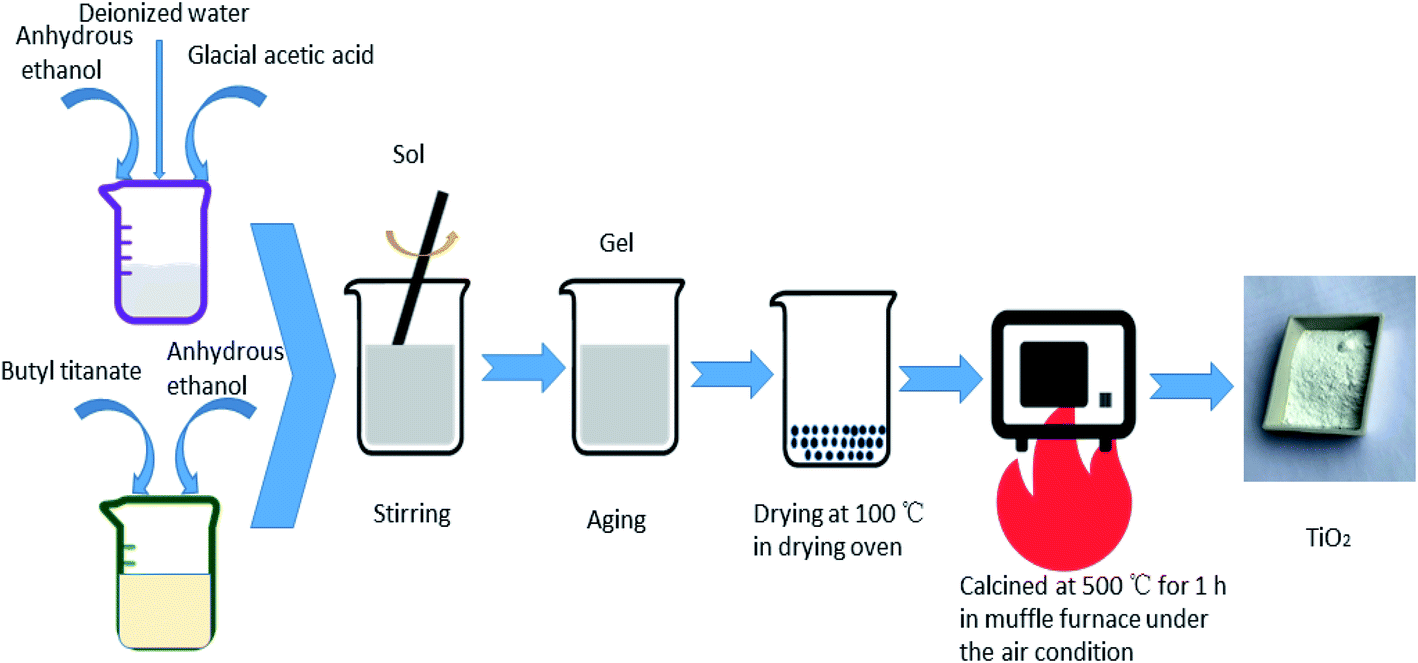
All the TiO2 photocatalysts were prepared by sol–gel method. The specific process of preparation pure TiO2 was as follows: solution A was prepared by adding butyl titanate in a volume ratio of 1![[thin space (1/6-em)]](https://www.rsc.org/images/entities/char_2009.gif) :2 to anhydrous ethanol in a beaker. Solution B was prepared by adding anhydrous ethanol, glacial acetic acid and deionized water in a volume ratio of 4:5:5. Solution B was added to solution A dropwise. The resulting mixture was stirred until a sol formed. A gel formed after aging. The obtained gel was dried at 100 °C and then heat treated at 500 °C for 1 h to obtain pure TiO2. For the preparation of Ag-modified TiO2 and Fe-doped TiO2, certain amounts of AgNO3 or Fe(NO3)3·9H2O were added into solution B. The atomic percentages of Ag/Ti or Fe/Ti were 0.5%, 1%, 2% and 4%, respectively. Keep other steps unchanged to obtain different concentrations of Ag modified TiO2 and Fe doped TiO2 which are recorded as 0.5% Ag–TiO2, 1% Ag–TiO2, 2% Ag–TiO2, 4% Ag–TiO2, 0.5% Fe–TiO2, 1% Fe–TiO2, 2% Fe–TiO2 and 4% Fe–TiO2. AgNO3 and Fe(NO3)3·9H2O were simultaneously added into solution B to prepare Ag/Fe co-modified TiO2. Both the molar ratios of Ag/Ti and Fe/Ti are 1%, and the Ag/Fe co-modified TiO2 is labeled as 1% Ag/1% Fe–TiO2. The preparation process is shown in Fig. 1.
:2 to anhydrous ethanol in a beaker. Solution B was prepared by adding anhydrous ethanol, glacial acetic acid and deionized water in a volume ratio of 4:5:5. Solution B was added to solution A dropwise. The resulting mixture was stirred until a sol formed. A gel formed after aging. The obtained gel was dried at 100 °C and then heat treated at 500 °C for 1 h to obtain pure TiO2. For the preparation of Ag-modified TiO2 and Fe-doped TiO2, certain amounts of AgNO3 or Fe(NO3)3·9H2O were added into solution B. The atomic percentages of Ag/Ti or Fe/Ti were 0.5%, 1%, 2% and 4%, respectively. Keep other steps unchanged to obtain different concentrations of Ag modified TiO2 and Fe doped TiO2 which are recorded as 0.5% Ag–TiO2, 1% Ag–TiO2, 2% Ag–TiO2, 4% Ag–TiO2, 0.5% Fe–TiO2, 1% Fe–TiO2, 2% Fe–TiO2 and 4% Fe–TiO2. AgNO3 and Fe(NO3)3·9H2O were simultaneously added into solution B to prepare Ag/Fe co-modified TiO2. Both the molar ratios of Ag/Ti and Fe/Ti are 1%, and the Ag/Fe co-modified TiO2 is labeled as 1% Ag/1% Fe–TiO2. The preparation process is shown in Fig. 1.
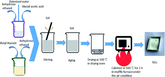 |
| | Fig. 1 The preparation process of TiO2. | |
Characterization
The phase structure of photocatalysts was determined using an X-ray diffractometer (XRD). Element composition and valence state were analyzed by an X-ray photoelectron spectroscopy (XPS). Surface morphologies were observed by a field emission scanning electron microscopy (FESEM) and a transmission electron microscopy (TEM). Photoluminescence (PL) spectra were recorded through a luminescence spectrometer. UV-vis diffuse reflectance spectra (DRS) were recorded using a spectrophotometer. Specific surface areas were determined by the Brunauer Emmett Teller (BET) method.
Photocatalytic test
Add 100 mL rhodamine B (RhB) solution (10 mg L−1) and 0 1 g of TiO2 photocatalyst to the beaker. The mixture was ultrasonically dispersed for 10 minutes, and then stirred to establish the adsorption–desorption equilibrium in dark for 30 min. A 250 W xenon lamp was employed as a light source and a small amount of suspension was taken every 30 minutes. After centrifugation, the supernatant was extracted and the absorbance of RhB was measured with a spectrophotometer at the wavelength of 553 nm. The decolorization rate D (%) was calculated as follows:
In the formula, A0 is the initial absorbance, and At is the absorbance at time t.
Results and discussion
XRD analysis
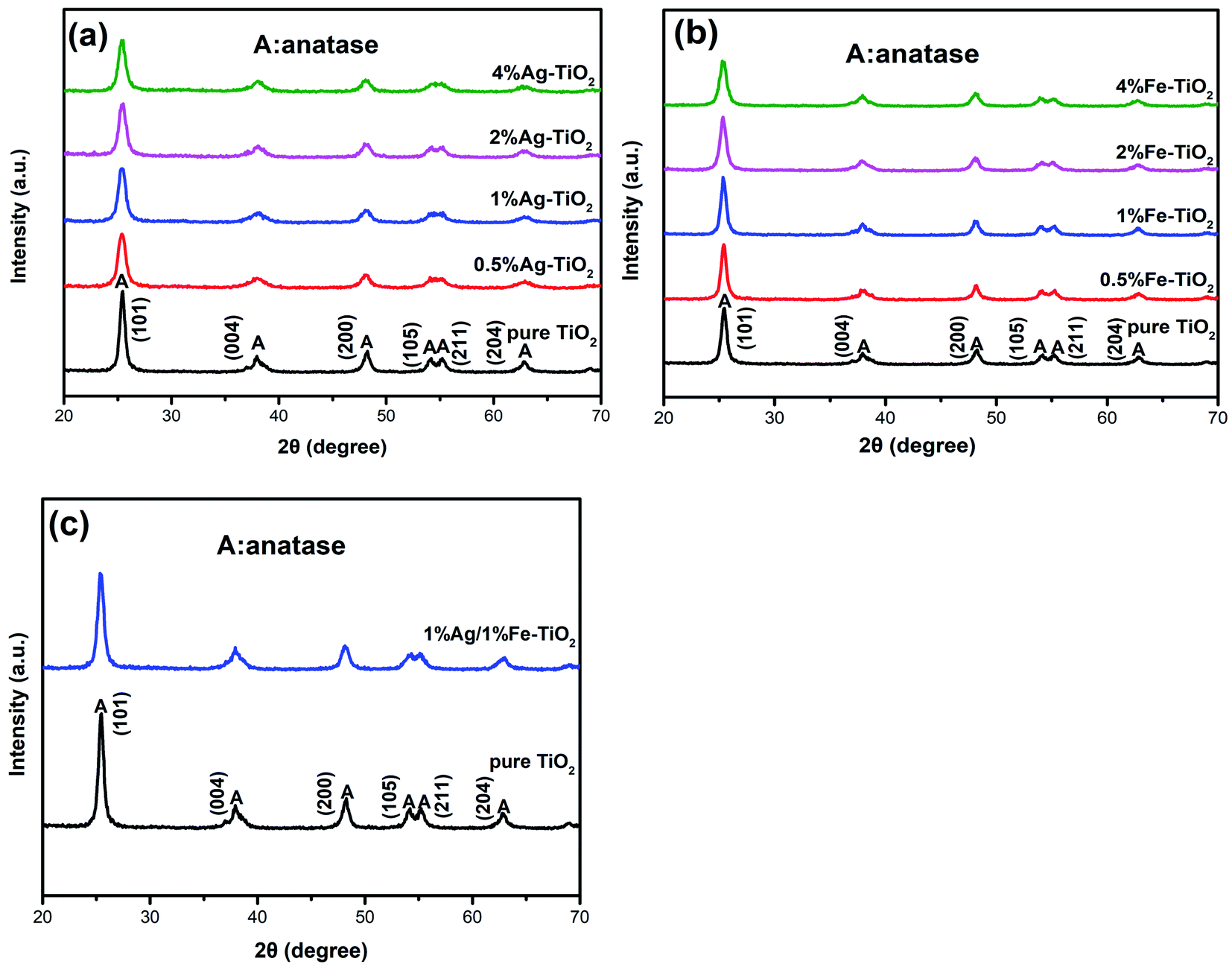
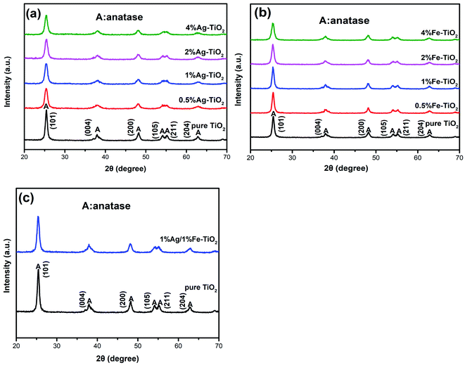
Fig. 2 shows the XRD patterns of pure TiO2, Ag–TiO2, Fe–TiO2 and 1% Ag/1% Fe–TiO2. In Fig. 2(a), the peaks of pure TiO2 at 25.3°, 37.9°, 48.1°, 53.9°, 55.1°and 62.8° correspond to (101), (004), (200), (105), (211) and (204) crystal planes of anatase structure, respectively. It is observed that Ag–TiO2, Fe–TiO2 and 1% Ag/1% Fe–TiO2 also form anatase structure, suggesting that the crystal structure of TiO2 is not significantly affected by Ag or Fe adding. However, the widths of diffraction peaks in Ag–TiO2, Fe–TiO2 and 1% Ag/1% Fe–TiO2 are wider and the intensities are lower than pure TiO2, indicating that the crystallinity of TiO2 is reduced and the crystal grain is refined.26,30 The grain sizes of TiO2 are calculated by Scherrer formula21 and the results are shown in Table 1. Yu et al.31 believe that the addition of dopants hinders the contact between TiO2 particles and inhibits the growth of grains during the heat treatment process, resulting in the decrease of grain size. The absence of diffraction peaks associated with Fe may be attributed to the fact that Fe3+ ions can replace Ti4+ ions into TiO2 lattices due to their close ionic radius.26,32,33 On the other hand, since the radius of Ag atom is much larger than that of Ti4+, it is difficult to enter TiO2 lattices. Ag particles probably disperse on TiO2 surface in the form of metallic Ag.34,35
 |
| | Fig. 2 XRD patterns of (a) Ag–TiO2, (b) Fe–TiO2 and (c) 1% Ag/1% Fe–TiO2. | |
Table 1 The crystallite sizes of samples
| Samples |
Crystallite size (nm) |
Samples |
Crystallite size (nm) |
| Pure TiO2 |
16.0 |
0.5% Fe–TiO2 |
15.1 |
| 0.5% Ag–TiO2 |
11.2 |
1% Fe–TiO2 |
15.9 |
| 1% Ag–TiO2 |
11.6 |
2% Fe–TiO2 |
13.7 |
| 2% Ag–TiO2 |
11.9 |
4% Fe–TiO2 |
12.3 |
| 4% Ag–TiO2 |
12.0 |
1% Ag/1% Fe–TiO2 |
13.3 |
XPS analysis
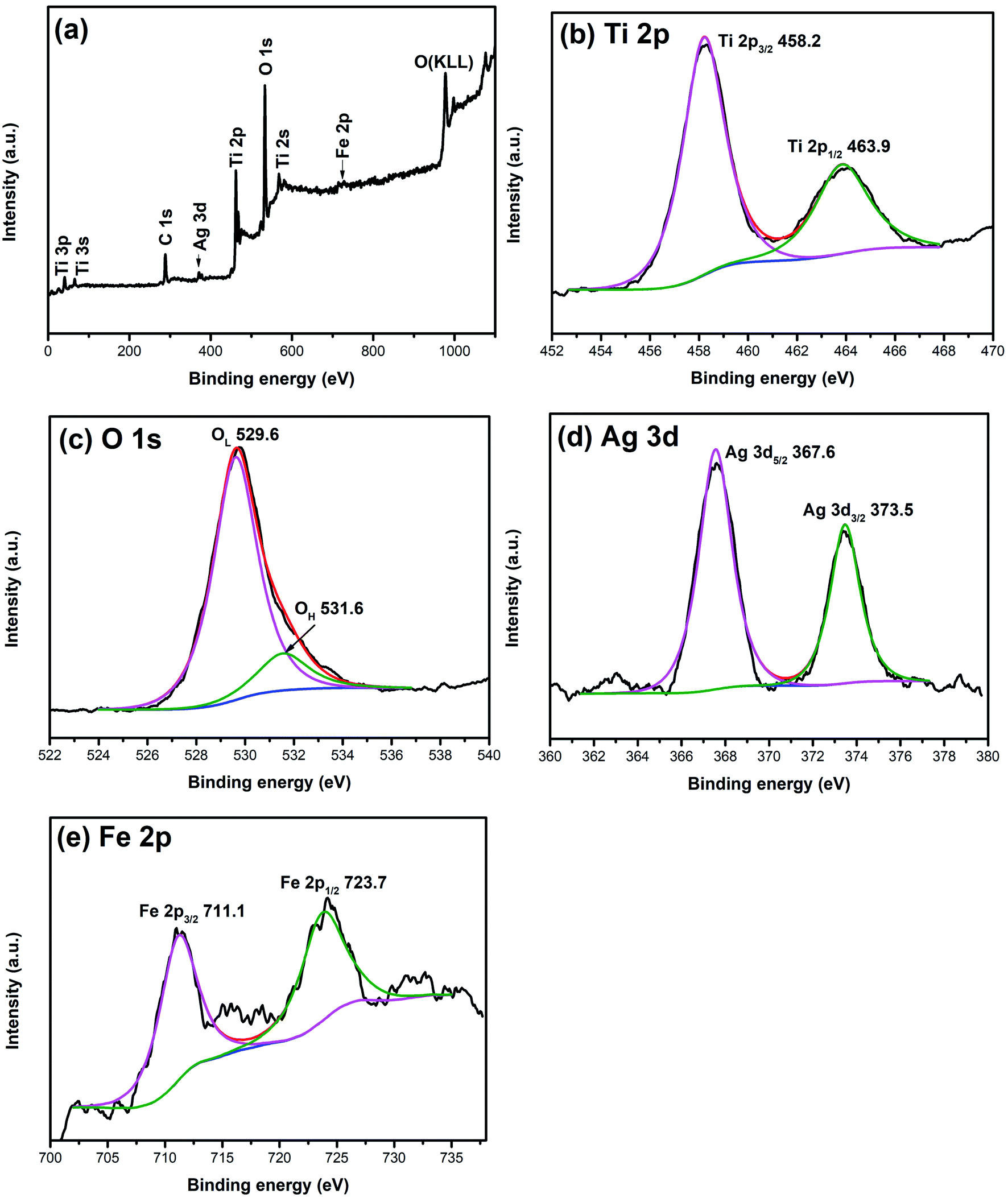
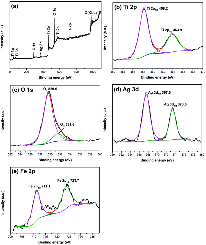
XPS is widely used to investigate the chemical valence of elements. To verify the valence states of Ag and Fe elements, XPS analysis of 1% Ag/1% Fe–TiO2 has been carried out and the results are shown in Fig. 3. The C, Ti, O, Ag and Fe signal peaks appear in the full spectrum (Fig. 3(a)), meaning that there are C, Ti, O, Ag and Fe elements in the sample. The appearance of C 1s peak may be derived from C remaining in the organic calcination process. In Fig. 3(b), two peaks at 458.2 eV and 463.9 eV corresponding to Ti 2p3/2 and Ti 2p1/2 and the splitting energy between Ti 2p3/2 and Ti 2p1/2 (5.7 eV) indicate that the state of Ti ions is Ti4+.36–38 Fig. 3(c) presents two peaks at 529.6 eV and 531.6 eV, ascribing to Ti–O bonds in TiO2 lattices (OL) and surface hydroxyl groups (OH), respectively.39,40 In Fig. 3(d), the peaks at 367.6 eV and 373.5 eV can be assigned to Ag 3d5/2 and Ag 3d3/2, respectively, which suggests that the Ag element exists as Ag0 in the sample.34,41,42 Two peaks at 711.1 eV and 723.7 eV in Fig. 3(e) attribute to Fe 2p3/2 and Fe 2p1/2, which indicates Fe element exists as Fe3+.27,32,43,44
 |
| | Fig. 3 XPS spectra of 1% Ag/1% Fe–TiO2: (a) total spectrum, (b) Ti 2p, (c) O 1s, (d) Ag 3d and (e) Fe 2p. | |
SEM and TEM images
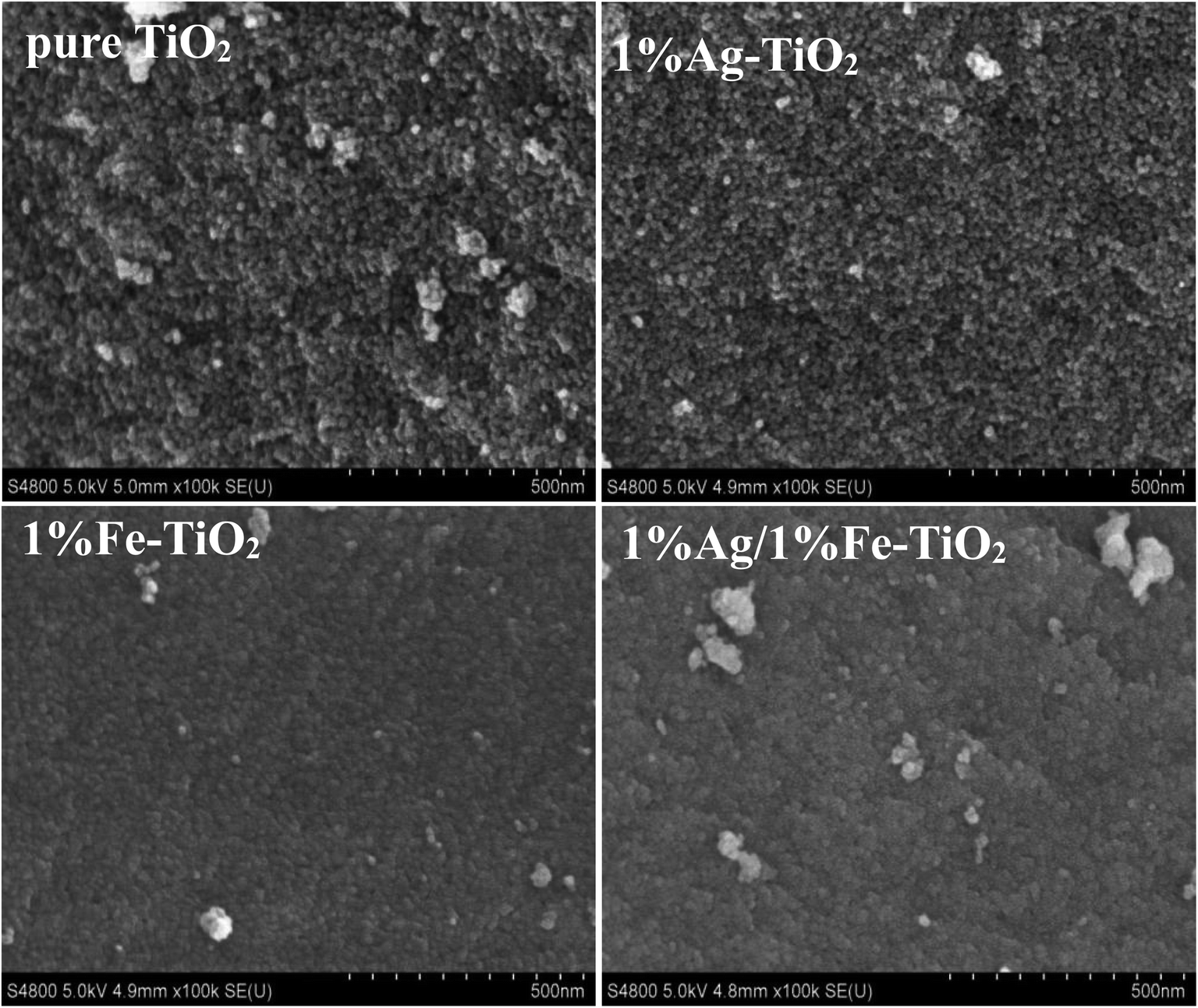
Fig. 4 presents the SEM images of pure TiO2, 1% Ag–TiO2, 1% Fe–TiO2, and 1% Ag/1% Fe–TiO2. It is observed that the particles are nearly spherical. Among them, pure TiO2 and 1% Ag–TiO2 particles are fine and disperse relatively uniform, however, the particles in 1% Fe–TiO2 and 1% Ag/1% Fe–TiO2 present obvious agglomeration.
 |
| | Fig. 4 SEM images of pure TiO2, 1% Ag–TiO2, 1% Fe–TiO2 and 1% Ag/1% Fe–TiO2. | |
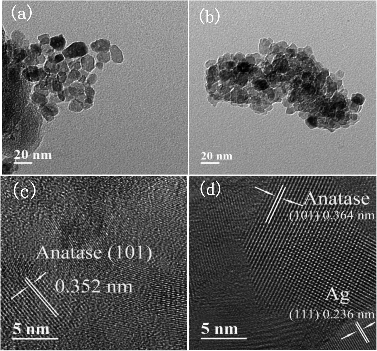
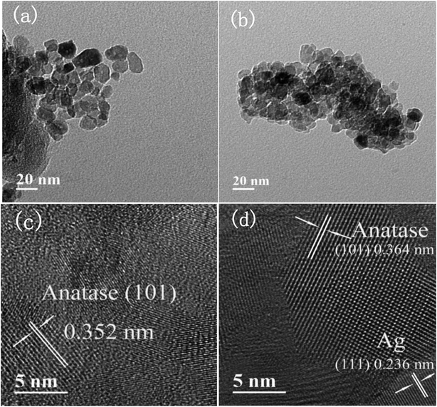
Fig. 5(a) and (b) are TEM images of pure TiO2 and 1% Ag/1% Fe–TiO2, from which we can see that the particle size in pure TiO2 is about 15–20 nm, while it is arranged from 10 to 15 nm in 1% Ag/1% Fe–TiO2. Moreover, pure TiO2 shows better particle dispersion than 1% Ag/1% Fe–TiO2, which is consistent with SEM images. The HRTEM images of pure TiO2 and 1% Ag/1% Fe–TiO2 are presented in Fig. 5(c) and (d), respectively. Both the labeled interplanar spacing values in pure TiO2 (0.352 nm) and 1% Ag/1% Fe–TiO2 (0.364 nm) correspond to the anatase (101) crystal plane.45 Since the radius of Fe3+ ions is larger than of Ti4+ ions, the substitution of Fe3+ for Ti4+ into crystal lattices causes lattice expansion, consequently, the anatase (101) plane spacing of 1% Ag/1% Fe–TiO2 is slightly larger than that of pure TiO2.25 In Fig. 5(d), the marked interplanar spacing (0.236 nm) can be attributed to the (111) crystal plane of metallic Ag0,34,39 which is in accord with XPS results.
 |
| | Fig. 5 TEM images of (a) pure TiO2, (b) 1% Ag/1% Fe–TiO2, HRTEM images of (c) pure TiO2, and (d) 1% Ag/1% Fe–TiO2. | |
Photocatalytic performance
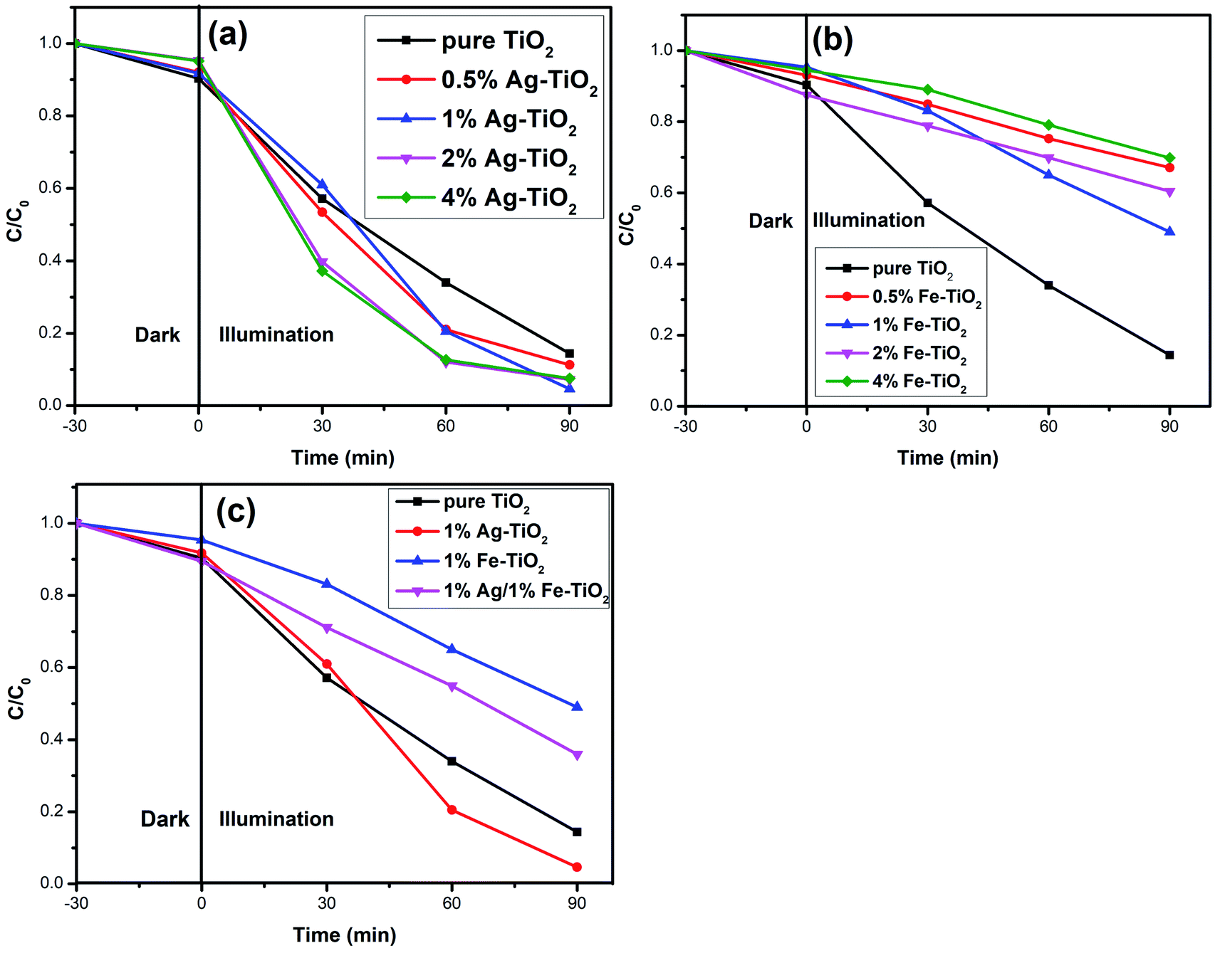
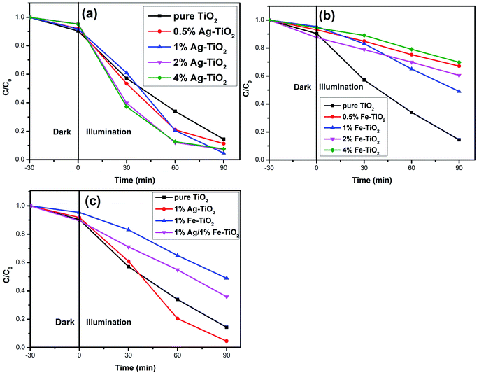
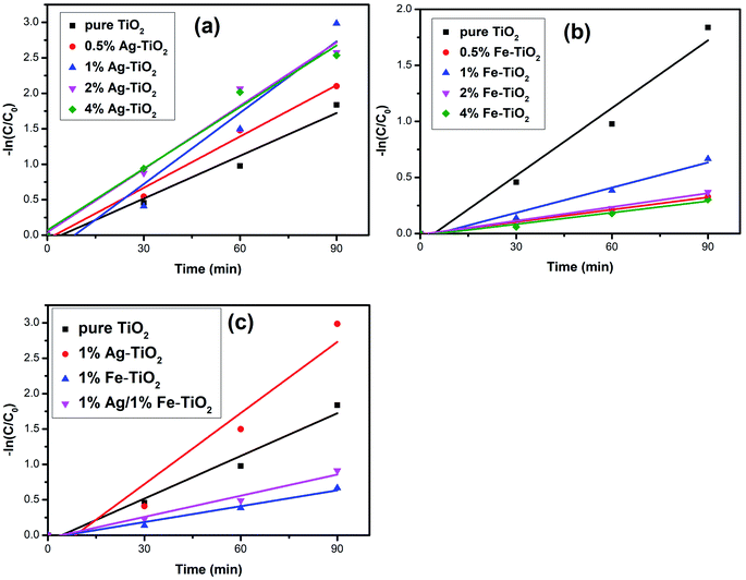
Photodegradation results. The photocatalytic activity of photocatalysts was evaluated via the decolorization rate of RhB and the results are presented in Fig. 6. The RhB decolorization rate of pure TiO2 is 85.7% after 90 min of reaction. Ag–TiO2 samples show higher photocatalytic activity than pure TiO2. The decolorization rates of 0.5% Ag–TiO2, 1% Ag–TiO2, 2% Ag–TiO2 and 4% Ag–TiO2 are 88.8%, 95.4%, 92.8% and 92.5%, respectively. 1% Ag–TiO2 exhibits the best photocatalytic activity and the decolorization rate of RhB decreases when Ag content exceeds 1%. Unexpectedly, the photocatalytic activity of TiO2 decreases after Fe doping. The decolorization rates of 0.5% Fe–TiO2, 1% Fe–TiO2, 2% Fe–TiO2 and 4% Fe–TiO2 are 33.3%, 51.3%, 39.9% and 30.6%, respectively. It is clear that the addition of Ag improves the photocatalytic performance, while Fe is the opposite. The decolorization rate of 1% Ag/1% Fe–TiO2 is 64.3%, suggesting that its photocatalytic activity is higher than Fe–TiO2 but lower than pure TiO2. The decolorization of RhB by TiO2 can be considered as a first-order reaction,17,19,46 and the calculation formula of the reaction rate constant k is as follows:
where t is the reaction time, C0 and Ct are the initial concentration and the concentration at time t. The first-order reaction kinetics fit curves are shown in Fig. 7. It is calculated that the reaction rate constant of pure TiO2 is 0.020 min−1. Ag–TiO2 samples show higher reaction rates than pure TiO2, and the reaction rate constants of 0.5% Ag–TiO2, 1% Ag–TiO2, 2% Ag–TiO2 and 4% Ag–TiO2 are 0.024 min−1, 0.034 min−1, 0.030 min−1 and 0.029 min−1, respectively. The reaction rate constants of 0.5% Fe–TiO2, 1% Fe–TiO2, 2% Fe–TiO2 and 4% Fe–TiO2 are 0.0036 min−1, 0.0075 min−1, 0.0041 min−1 and 0.0034 min−1, respectively, implying that the reaction rates of Fe–TiO2 are much lower than pure TiO2. The reaction rate constant of 1% Ag/1% Fe–TiO2 is 0.0099 min−1, which is higher than Fe–TiO2 but lower than pure TiO2.
 |
| | Fig. 6 Decolorization rate curves of RhB for (a) Ag–TiO2, (b) Fe–TiO2, and (c) 1% Ag/1% Fe–TiO2. | |
 |
| | Fig. 7 Kinetics linear simulation curves of (a) Ag–TiO2, (b) Fe–TiO2, and (c) 1% Ag/1% Fe–TiO2. | |
PL spectra
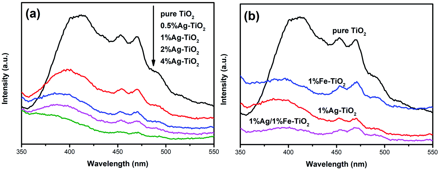
In order to analyze the influence of addition with Ag and Fe on the photogenerated electron–hole recombination of TiO2, the PL tests have been implemented and the results are shown in Fig. 8. The PL peaks originate from the recombination of photoinduced electrons and holes. Therefore, a lower PL peak intensity represents a lower recombination rate.27,38 The PL peak intensity of Ag–TiO2 is lower than that of pure TiO2, which suggests that the recombination of photoinduced pairs is inhibited by Ag modification. When exposed to light source, electrons in the valence band are excited to the conduction band, forming photogenerated electrons, leaving photogenerated holes on valence band. Photoinduced electrons can be transferred to Ag0 particles which are deposited on TiO2 surface, reducing the recombination.6,18,19,34 Several researches have reported that there is an optimum concentration of Ag, above which new recombination centers will be formed thus increases recombination rate.18,34 However, PL peak intensity decreases with the increasing Ag concentration in the present work, indicating that new recombination centers have not been formed when the Ag concentration reaches 4%. The PL peak intensity decreases with the increase of the amount of noble metal element, which also has been reported in previous work.47 Photocatalytic experiments show that high Ag concentration is not conducive to photocatalytic activity and 1% Ag–TiO2 exhibits the highest decolorization rate. The decrease in photocatalytic performance of 2% Ag–TiO2 and 4% Ag–TiO2 should be attributed to the fact that Ag0 particles are deposited on the surface of TiO2 particles, and as the Ag concentration increases, excessive Ag particles will cover TiO2 surface, reducing the utilization of light and reactive sites.13,34
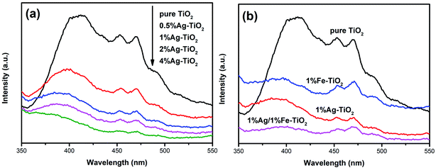 |
| | Fig. 8 PL spectra of (a) Ag–TiO2, (b) pure TiO2, 1% Ag–TiO2, 1% Fe–TiO2 and 1% Ag/1% Fe–TiO2. | |
The photocatalytic activities of Fe–TiO2 and 1% Ag/1% Fe–TiO2 are lower than pure TiO2. Similar results have also been reported that the addition of metal ions reduces the photocatalytic performance of TiO2.23 There is a viewpoint that doping metal ions leads to a decrease in crystallinity and an increase in lattice defects. The formed lattice defects act as recombination centers, promoting the recombination of photoinduced pairs and suppressing the photocatalytic activity.23,48,49 In contrast, from Fig. 8(b), it is clear that the PL intensities of 1% Fe–TiO2 and 1% Ag/1% Fe–TiO2 are lower than that of pure TiO2, proving that the addition of Fe is beneficial to decreasing the recombination. Fe3+ ions entering the crystal lattices to replace Ti4+ ions will cause lattice distortion and defects, capturing photogenerated electrons and reducing the recombination of photogenerated charges.7,33 Moreover, 1% Ag/1% Fe–TiO2 shows the lowest PL intensity, suggesting that there is a synergistic effect in suppressing photoinduced pairs recombination owing to adding Ag and Fe simultaneously. Therefore, we can conclude that the decrease in photocatalytic performance of Fe–TiO2 and 1% Ag/1% Fe–TiO2 should not be attributed to the promotion of recombination with Fe adding.
DRS analysis
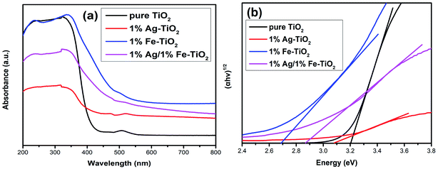
The energy gap (Eg) of photocatalyst affects the absorption of light source, which is an important factor for photocatalytic performance. The influence of doping on the Eg of TiO2 is controversial, and both redshift6,7,9,26,27,34 and blueshift24 have been reported. Fig. 9 depicts the UV-visible absorption spectra of pure TiO2 and 1% Ag–TiO2, 1% Fe–TiO2 and 1% Ag/1% Fe–TiO2. It is observed that the addition of Ag and Fe causes a redshift in the absorption edge of TiO2. The Eg was calculated based on the Kubelka–Munk equation and Tauc's plots.3,32,35,50 The Eg of pure TiO2, 1% Ag–TiO2, 1% Fe–TiO2 and 1% Ag/1% Fe–TiO2 are estimated to be 3.20 eV, 3.09 eV, 2.69 eV and 2.87 eV, respectively. The results show that the addition of Ag and Fe is beneficial to increasing the absorption of visible light. It can be concluded from XPS and TEM results that Ag element exists in the form of Ag0. Due to the surface plasmon resonance (SPR) effect of Ag particles deposited on TiO2 surface, the absorption of visible light can be enhanced, reducing the Eg.15,16,34,36,37 On the other hand, the substitutions of Ti4+ ions with Fe3+ ions form impurity energy levels between the conduction band and valence band in the forbidden band, thereby decreasing the Eg.5,7,10,21,33,43,51 Therefore, the change of Eg is not the main reason for the decreased photocatalytic performance of Fe–TiO2 and 1% Ag/1% Fe–TiO2.
 |
| | Fig. 9 (a) UV-visible absorption spectra and (b) plots of (αhν)1/2 versus energy (hν) of pure TiO2, 1% Ag–TiO2, 1% Fe–TiO2 and 1% Ag/1% Fe–TiO2. | |
BET analysis
As is well known, photocatalyst with a larger specific surface area will provide more active reaction sites and increase light absorption, which is advantageous for photocatalytic performance.19,22,27,33 It is observed from SEM images that the 1% Fe–TiO2 particles have a larger agglomeration than pure TiO2, which may lead to the decrease of specific surface area. To verify this assumption, we have performed BET specific surface area tests and the results are shown in Table 2. The specific surface area of 1% Fe–TiO2 is 16.1 m2 g−1, which is much lower than that of pure TiO2 (63.8 m2 g−1). Some researchers believe that reduction in grain size will lead to an increase in specific surface area.48,51 In our work, the grain size of TiO2 is reduced by Ag or Fe modification, which is proved by XRD results, however, 1% Fe–TiO2 and 1% Ag/1% Fe–TiO2 possess smaller specific surface areas than pure TiO2. Wang et al.52 and Adyani et al.22 are convinced that the specific surface area of TiO2 is largely related to agglomeration degree. SEM and TEM images confirm an increase in particle agglomeration after Fe addition, which is the major reason for the decrease in specific surface area. It is the significant reduce in specific surface areas of Fe–TiO2 and 1% Ag/1% Fe–TiO2 that causes the decrease in their photocatalytic performance.
Table 2 Specific surface areas (SBET) of pure TiO2, 1% Ag–TiO2, 1% Fe–TiO2 and 1% Ag/1% Fe–TiO2
| Samples |
SBET (m2 g−1) |
| Pure TiO2 |
63.8 |
| 1% Ag–TiO2 |
59.4 |
| 1% Fe–TiO2 |
16.1 |
| 1% Ag/1% Fe–TiO2 |
49.8 |
From another perspective, as the surface areas of samples are quite different, the intrinsic photocatalytic activity (normalized by BET surface area) can be used as a reference. The intrinsic photocatalytic activity (IPA) is calculated as follows:53
| IPA (mg min−1 m−2) = mRhB/tSBETms |
where
mRhB is the weight of RhB which has been degraded,
t is the reaction time (90 min),
SBET is the surface area, and
ms is the weight of sample used in each test (0.1 g).
The IPA of pure TiO2, 1% Ag–TiO2, 1% Fe–TiO2 and 1% Ag/1% Fe–TiO2 are 0.00149 mg min−1 m−2, 0.00178 mg min−1 m−2, 0.00354 mg min−1 m−2 and 0.00143 mg min−1 m−2. The results show that 1% Fe–TiO2 has relatively high intrinsic photocatalytic activity.
Conclusions
In summary, pure TiO2, Ag–TiO2, Fe–TiO2 and 1% Ag/1% Fe–TiO2 were prepared by sol–gel method. The results of the decolorization rate of RhB indicate that the photocatalytic activities of Ag–TiO2 are higher than pure TiO2, while the photocatalytic activities of Fe–TiO2 and 1% Ag/1% Fe–TiO2 are lower than pure TiO2. The increased photocatalytic activity of Ag–TiO2 can be attributed to the reduction of photoinduced pairs recombination rate and energy gap. The specific surface areas of Fe–TiO2 and 1% Ag/1% Fe–TiO2 are much lower than pure TiO2, leading to the decreases in their photocatalytic properties.
Conflicts of interest
There are no conflicts to declare.
Acknowledgements
This work was supported by the Applied Basic Research Programs of Sichuan Province, China (Grant No. 2019JY0664, 2018JY0062), the Technology Innovation Research and Development Project of Chengdu City (Grant No. 2019-YFYF-00013-SN) and the Training Program for Innovation of Chengdu University, China (Grant No. 201911079002, S201911079042).
References
- B. Singaram, K. Varadharajan, J. Jeyaram, R. Rajendran and V. Jayavel, J. Photochem. Photobiol., A, 2017, 349, 91–99 CrossRef CAS.
- V. Koli and J. Kim, Mater. Sci. Semicond. Process., 2019, 94, 70–79 CrossRef CAS.
- J. A. B. Pérez, M. Courel, M. Pal, F. P. Delgado and N. R. Mathews, Ceram. Int., 2017, 43, 15777–157840 CrossRef.
- P. N. Gaikwad, P. P. Hankare, T. M. Wandre, K. M. Garadkar and R. Sasikala, Mater. Sci. Eng., B, 2016, 205, 40–45 CrossRef CAS.
- T. T. Loan, N. A. Bang, V. H. Huong and N. N. Long, Opt. Mater., 2017, 69, 30–37 CrossRef CAS.
- N. Wei, H. Z. Cui, Q. Song, L. Q. Zhang, X. J. Song, K. Wang, Y. F. Zhang, J. Li, J. Wen and J. Tian, Appl. Catal., B, 2016, 198, 83–90 CrossRef CAS.
- P. Benjwal, B. De and K. K. Kar, Appl. Surf. Sci., 2018, 427, 262–272 CrossRef CAS.
- Y. C. Zhang, N. Afzal, L. Pan, X. W. Zhang and J. J. Zou, Adv. Sci., 2019, 6, 1900053 CrossRef.
- R. Ambati and P. R. Gogate, Ultrason. Sonochem., 2018, 40, 91–100 CrossRef CAS.
- Y. Y. Zhang, D. Gu, L. Y. Zhu and B. H. Wang, Appl. Surf. Sci., 2017, 420, 896–904 CrossRef CAS.
- H. B. Jiang, J. Xing, Z. P. Chen, F. Tian, Q. Cuan, X. Q. Gong and H. G. Yang, Catal. Today, 2014, 225, 18–23 CrossRef CAS.
- J. J. Li, X. Y. Deng, R. N. Guo, B. Li, Q. F. Cheng and X. W. Cheng, J. Taiwan Inst. Chem. Eng., 2018, 87, 174–181 CrossRef CAS.
- Z. L. Yang, J. Lu, W. C. Ye, C. S. Yu and Y. L. Chang, Appl. Surf. Sci., 2017, 392, 472–480 CrossRef CAS.
- W. Lin, H. Zheng, P. Y. Zhang and T. Z. Xu, Appl. Catal., A, 2016, 521, 75–82 CrossRef CAS.
- S. Naya and H. Tada, J. Catal., 2018, 364, 328–333 CrossRef CAS.
- S. Sadrieyeh and R. Malekfar, J. Non-Cryst. Solids, 2018, 489, 33–39 CrossRef CAS.
- D. Y. Zhou, Y. M. Liu, W. G. Zhang, W. Liang and F. Q. Yang, Thin Solid Films, 2017, 636, 490–498 CrossRef CAS.
- T. Ali, A. Ahmed, U. Alam, I. Uddin, P. Tripathi and M. Muneer, Mater. Chem. Phys., 2018, 212, 325–335 CrossRef CAS.
- T. Wang, J. X. Wei, H. M. Shi, M. Zhou, Y. Zhang, Q. Chen and Z. M. Zhang, Phys. E, 2017, 86, 103–110 CrossRef CAS.
- M. Salazar-Villanueva, A. Cruz-López, A. A. Zaldívar-Cadena, A. Tovar-Corona, M. L. Guevara-Romero and O. Vazquez-Cuchillo, Mater. Sci. Semicond. Process., 2017, 58, 8–14 CrossRef CAS.
- A. Arunachalam, S. Dhanapandian and C. Manoharan, Phys. E, 2016, 76, 35–46 CrossRef CAS.
- S. M. Adyani and M. Ghorbani, J. Rare Earths, 2018, 36, 72–85 CrossRef CAS.
- F. Bensouici, M. Bououdina, A. A. Dakhel, R. Tala-Ighil, M. Tounane, A. Iratni, T. Souier, S. Liu and W. Cai, Appl. Surf. Sci., 2017, 395, 110–116 CrossRef CAS.
- C. M. Malengreaux, S. L. Pirard, G. Leonard, J. G. Mahy, M. Herlitschke, B. Klobes, R. Hermann, B. Heinrichs and J. R. Bartlett, J. Alloys Compd., 2017, 691, 726–738 CrossRef CAS.
- M. C. Wu, P. Y. Wu, T. H. Lin and T. F. Lin, Appl. Surf. Sci., 2017, 430, 390–398 CrossRef.
- H. Moradi, A. Eshaghi, S. R. Hosseini and K. Ghani, Ultrason. Sonochem., 2016, 32, 314–319 CrossRef CAS.
- A. Kundu and A. Mondal, J. Mater. Sci.: Mater. Electron., 2019, 30, 3244–3256 CrossRef CAS.
- P. F. Zhang, X. W. Li, X. K. Wu, T. X. Zhao and L. S. Wen, J. Alloys Compd., 2016, 673, 405–410 CrossRef CAS.
- M. Khan, Z. Yi, S. R. Gul, U. Fawad and W. Muhammad, J. Phys. Chem. Solids, 2017, 110, 241–247 CrossRef CAS.
- Y. Chen and K. Liu, J. Hazard. Mater., 2017, 324, 139–150 CrossRef CAS.
- J. G. Yu, J. C. Yu and X. J. Zhao, J. Sol-Gel Sci. Technol., 2002, 24, 95–103 CrossRef CAS.
- S. Sood, A. Umar, S. K. Mehta and S. K. Kansal, J. Colloid Interface Sci., 2015, 450, 213–223 CrossRef CAS.
- J. P. Li, D. J. Ren, Z. X. Wu, J. Xu, Y. J. Bao, S. He and Y. H. Chen, J. Colloid Interface Sci., 2018, 530, 78–87 CrossRef CAS.
- X. X. Lin, F. Rong, D. G. Fu and C. W. Yuan, Powder Technol., 2012, 219, 173–178 CrossRef CAS.
- S. Naraginti, T. V. L. Thejaswini, D. Prabhakaran, A. Sivakumar, V. S. V. Satyanarayana and A. S. Arun Prasad, Spectrochim. Acta, Part A, 2015, 149, 571–579 CrossRef CAS.
- D. d. Gao, W. J. Liu, Y. Xu, P. Wang, J. J. Fan and H. G. Yu, Appl. Catal., B, 2020, 260, 118190 CrossRef CAS.
- X. Fan, J. Fan, X. Y. Hu, E. Z. Liu, L. M. Kang, C. N. Tang, Y. N. Ma, H. T. Wu and Y. Y. Li, Ceram. Int., 2014, 40, 15907–15917 CrossRef CAS.
- Y. Chen, Q. Wu, C. Zhou and Q. T. Jin, Powder Technol., 2017, 322, 296–300 CrossRef CAS.
- Y. Zhang, T. Wang, M. Zhou, Y. Wang and Z. M. Zhang, Ceram. Int., 2017, 43, 3118–3126 CrossRef CAS.
- S. Demirci, T. Dikici, M. Yurddaskal, S. Gultekin, M. Toparli and E. Celik, Appl. Surf. Sci., 2016, 390, 591–601 CrossRef CAS.
- Y. C. Yao, X. R. Dai, X. Y. Hu, S. Z. Huang and Z. Jin, Appl. Surf. Sci., 2016, 387, 469–476 CrossRef CAS.
- Y. P. Gao, P. F. Fang, F. T. Chen, Y. Liu, Z. Liu, D. H. Wang and Y. Q. Dai, Appl. Surf. Sci., 2013, 265, 796–801 CrossRef CAS.
- G. Q. Shen, L. Pan, Z. Lü, C. Q. Wang, F. Aleem, X. W. Zhang and J. J. Zou, Chin. J. Catal., 2018, 39, 920–928 CrossRef CAS.
- L. Pan, J. J. Zou, X. W. Zhang and L. Wang, Ind. Eng. Chem. Res., 2010, 49, 8526–8531 CrossRef CAS.
- D. D. Gao, X. H. Wu, P. Wang, Y. Xu, H. G. Yu and J. G. Yu, ACS Sustainable Chem. Eng., 2019, 7, 10084–10094 CrossRef CAS.
- D. Zhang, B. H. Wang, J. Q. Wang, H. M. Wang, S. X. Zhang and D. Gu, RSC Adv., 2019, 9, 2784–2791 RSC.
- X. J. Yang, X. L. Wu, J. Li and Y. Liu, RSC Adv., 2019, 9, 29097–29104 RSC.
- D. V. Dao, M. V. D. Bremt, Z. Koeller and T. K. Le, Powder Technol., 2016, 288, 366–370 CrossRef CAS.
- T. H. Le, A. T. Bui and T. K. Le, Powder Technol., 2014, 268, 173–176 CrossRef CAS.
- J. Tauc, R. Grigorovici and A. Vancu, Phys. Status Solidi, 1966, 15, 627–637 CrossRef CAS.
- K. Kalantari, M. Kalbasi, M. Sohrabi and S. J. Royaee, Ceram. Int., 2017, 43, 973–981 CrossRef CAS.
- Y. Z. Wang, Y. S. Wu, H. Yang, X. X. Xue and Z. H. Liu, Vacuum, 2016, 131, 58–64 CrossRef CAS.
- R. T. Guo, Q. L. Chen, H. L. Ding, Q. S. Wang, W. G. Pan, N. Z. Yang and C. Z. Lu, Catal. Commun., 2015, 69, 165–169 CrossRef CAS.
|
| This journal is © The Royal Society of Chemistry 2019 |
Click here to see how this site uses Cookies. View our privacy policy here. 
 Open Access Article
 This Open Access Article is licensed under a
  ab,
Hongyan Xua,
Yin Yaoa,
Hui Liua,
Juan Wanga,
Yun Pua,
Wei Feng
ab,
Hongyan Xua,
Yin Yaoa,
Hui Liua,
Juan Wanga,
Yun Pua,
Wei Feng