
 Open Access Article
 This Open Access Article is licensed under a Creative Commons Attribution-Non Commercial 3.0 Unported Licence
Three-dimensionally printed pressure sensor arrays from hysteresis-less stretchable piezoresistive composites†
Jong Hyun Kang‡
ab,
Ju Young Kim‡a,
Yejin Joac,
Hyun-Suk Kimb,
Sung Mook Jung a,
Su Yeon Leea,
Youngmin Choi*ac and
Sunho Jeong*d
a,
Su Yeon Leea,
Youngmin Choi*ac and
Sunho Jeong*d
aDivision of Advanced Materials, Korea Research Institute of Chemical Technology (KRICT), 141 Gajeong-ro, Yuseong-gu, Daejeon 305-600, Korea. E-mail: youngmin@krict.re.kr
bDepartment of Materials Science and Engineering, College of Engineering, Chungnam National University, 99 Daehak-ro, Yuseong-gu, Daejeon 305-764, Korea
cDepartment of Chemical Convergence Materials, Korea University of Science and Technology (UST), 217 Gajeong-ro, Yuseong-gu, Daejeon 305-350, Korea
dDepartment of Advanced Materials Engineering for Information and Electronics, Kyung Hee University, Yongin-si, Gyeonggi-do 17104, Korea. E-mail: sjeong@khu.ac.kr
First published on 4th December 2019
Abstract
In this study, we formulate three-dimensionally (3D) printable composite pastes employing electrostatically assembled-hybrid carbon and a polystyrene-polyisoprene-polystyrene tri-block copolymer elastomer for the fabrication of multi-stack printed piezoresistive pressure sensor arrays. To address a critical drawback of piezoresistive composite materials, we have developed a previously unrecognized strategy of incorporating a non-ionic amphiphilic surfactant, sorbitan trioleate, into composite materials. It is revealed that the surfactant with an appropriate amphiphilic property, represented by the hydrophilic-lipophilic balance (HLB) index of 1.8, allows for a reversible piezoresistive characteristic under a wide pressure range up to 30 kPa as well as a significant reduction of elastomer viscoelastic behavior. The 3D-printed pressure sensor arrays exhibit a sensitivity of 0.31 kPa−1 in a linear trend, and it is demonstrated successfully that the position-addressable array device is capable of spatially detecting objects up to a pressure level of 22.1 kPa.
Introduction
Flexible pressure sensors are capable of collecting significant physical data to meet specific demands from the human body and in the processes by which humans interact with their external surroundings.1,2 Recently, this capability has opened up the practical possibility of various future applications, including human–machine interfaces, soft robotics, e-skin, and medical diagnosis.3–11 Traditional pressure sensors, which are composed of stiff constituent materials, are in general impracticable for such flexible/wearable platform technologies. A variety of flexible pressure sensors have been developed with a great improvement in performance, most importantly in terms of sensitivity and measurable pressure range.12–21The flexible pressure sensors developed to date can be categorized by their measurable characteristics of capacitance, piezoresistivity, and piezoelectricity. Among them, capacitance-based pressure sensors have been widely developed, with a distinct advantage in terms of both sensitivity and resolution;12–14 but, they require accurate measurement systems for gathering capacitance signals ranging a few tens of pF and might be implemented with complex readout units in practical applications. In the case of piezoresistive pressure sensors, electrical signals can be collected over a wide detection range by simply measuring pressure-dependent variation in either current or resistance. Simply, there are different two modes. In a “type I” mode, a partially-interconnected conductive framework inside pre-formed structures or porous composites is varied as a function of applied pressure, which regulates conductive pathways, increasing the current level under a provision of pressure.15–17 However, these devices tend to suffer from non-linear characteristics in sensitivity. Recently, it was reported that such a limited behavior is resolved with a specific structural strategy of, for example, increasing the number of sensing layers.18 The operation mechanism of the “type II” mode is similar to that of piezoresistive strain sensor devices. When an external pressure is applied to stretchable sensor layers, the stretchable conductive networks inside them are reconstructed with a proportional increment in resistance as a function of pressure level.19 This type of device possesses practical advantages over its counterparts in terms of a moderately high sensitivity, a wide detection range, and a simple device architecture; however, there are the critical drawbacks of poor reversibility and a hysteresis, attributable to the intrinsic viscoelastic property of elastomeric materials. Piezoelectric pressure sensor devices are applicable to self-powered circuitries;20,21 however, due to the intrinsic nature of piezoelectricity, a static pressure signal is not obtainable without the aid of other measurement units, and a chemical design for endowing inorganic ceramic materials with flexibility should be taken into consideration.
Another issue that is of paramount importance in practical applications, is a processability in the fabrication of position-addressable pressure sensor arrays. To date, most pressure sensor arrays have been fabricated with vacuum-deposited electrode layers and mask-based patterning techniques.14,18,19,22,23 Alternatively, mold-based soft-patterning techniques have been suggested for easy accessibility toward a facile patterning process.24,25 Considering the dimensions of objects that are prone to be detected in pressure sensor applications, a printing technique that is mask-free, inexpensive, large-area processable, is more appropriate for the fabrication of pressure sensor devices; however, directly-printed pressure sensor arrays have been rarely reported due to the difficulty of formulating printable fluids that can form highly-functioning sensing layers.
In this study, we have formulated three-dimensionally printable (3D-printable) composite pastes for “type II” mode-piezoresistive pressure sensor arrays. Irreversible behavior, a critical impediment in elastomeric material, is resolved through an approach of incorporating a surfactant with a specific chemical property. It is revealed clearly that a reversible behavior of piezoelectric composite materials is adjustable depending on the kind of surfactant and the relative amount of surfactant. As a conductive moiety, hybrid carbons were synthesized from non-destructively amine-functionalized multi-walled carbon nanotubes (NH2MWNTs) and graphene oxides (GOs). A mixture of surfactant-mediated elastomer and hybrid carbons is formulated into 3D-printable paste, with a characteristic rheological property suitable for forming vertically-stackable structures. The 3D-printed pressure sensor array is demonstrated on pre-structured polydimethylsiloxane (PDMS) substrate, with an excellent sensitivity of 0.31 kPa−1 in a wide range up to 30 kPa, enough to detect most human daily activities.
Results and discussion
The preparation procedures of the 3D-printable piezoresistive sensor paste and the 3D printing process are shown in Scheme 1. Hybrid carbons were synthesized from electrostatically-driven assemblies between negatively-charged GOs and positively-charged NH2MWNTs in an aqueous medium. The NH2MWNTs were synthesized through a non-destructive method without the involvement of the conventional acid-based surface activation process. The N,N′-di(2-aminoethyl)-perylene-3,4,9,10-tetracarboxylic diimide (AE-PTDI), synthesized by reacting perylene-3,4,9,10-tetracarboxylic dianhydride (PTDA) with ethylenediamine, was immobilized on the surfaces of the MWNTs via a strong π–π stacking interaction.26,27 The synthesized hybrid carbon was used as a filler in piezoresistive composites. The piezoresistive performance of a hybrid carbon material varies predominantly according to the ratio of NH2MWNT to GO.28 A hybrid carbon filler with a ratio of 9 was used in this study because it lacks free NH2MWNTs outside the regime of GOs and shows a more reversible piezoresistive response.28 The SIS (styrene-isoprene-styrene) thermoplastic tri-block copolymer was chosen as an elastomeric matrix; the presence of isoprene segment with a glass transition temperature below −60 °C allows for a low elastic modulus and an excellent adhesion property.29 Notably, a non-ionic amphiphilic surfactant, sorbitan trioleate (STO), sorbitan monooleate (SMO), or sorbitan monolaurate (SML), was incorporated to further lower the elastic modulus of the elastomeric matrix and to adjust the reversible movement of carbon fillers in composites. Then, the highly viscous, 3D-printable pastes were formulated with the addition of a small amount of solvent, 1,3-dichlorobenzene (DCB), and were printed along the surface of three-dimensional structures for the fabrication of the piezoresistive pressure sensor arrays.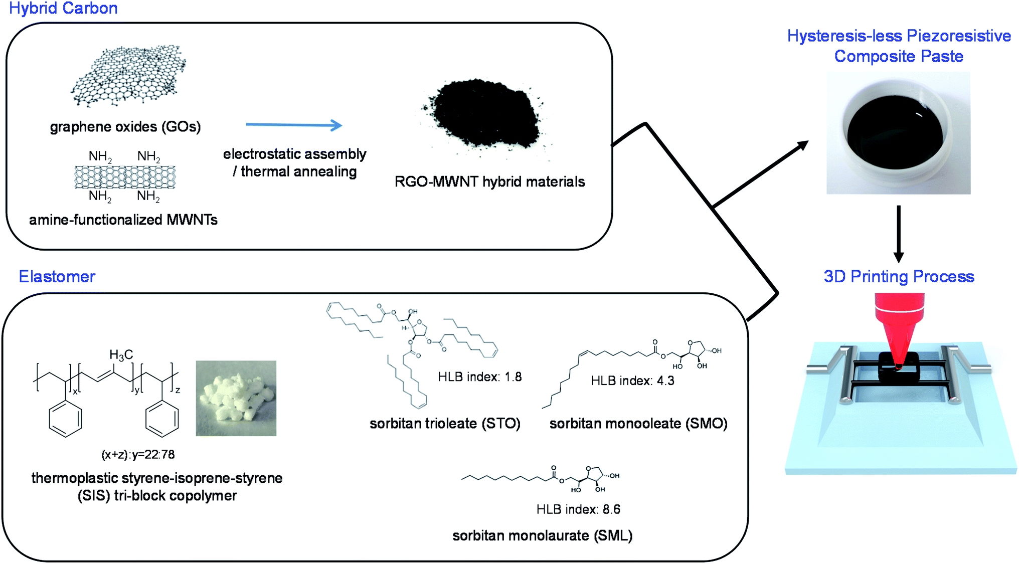 | ||
| Scheme 1 Schematics of preparation procedures of hysteresis-less piezoresistive composite pastes and 3D printing process for the fabrication of pressure sensor array devices. | ||
At first, the electrical characteristics of the sensor layers were evaluated except the involvement of processing parameters. The carbon composite pastes were printed on (tridecafluoro-1,1,2,2-tetrahydrooctyl)trichlorosilane-treated hydrophobic glass substrates, and the detached printed layers were transferred onto well structures, which were fabricated by a 3D stereolithography (SLA) printing process. Both ends of the sensor layers were electrically connected by Cu wires with commercial silver epoxy pastes, as shown in Fig. 1a. The composite layers including pristine, STO-added, SMO-added, and SML-added SIS elastomeric matrix are denoted as P-SIS, STO–SIS, SMO–SIS, and SML–SIS, respectively. For the case of the P-SIS sensor, various abnormal piezoresistive responses were observed (Fig. 1b): (i) an electrical response not being recovered completely, (ii) a delay in resistance signal when the external pressure starts to decrease, and (iii) a noisy signal background in overall measurements. In piezoresistive sensors, abnormal resistance signals that do not precisely reflect a variation in stress or strain, are mainly attributable to the viscoelastic nature of elastomeric matrix surrounding conductive fillers and the irreversible transformation of conductive networks in the composite layers.30,31 Interestingly, as shown in the case of the STO–SIS sensor, such non-ideal behaviors were resolved clearly by the addition of a non-ionic amphiphilic STO surfactant with a composition of 30 wt% (Fig. 1c). The STO comprises three bulky hydrophobic chains and a hydrophilic core chemical moiety. It is observed that a resistance base line goes up slightly even in the STO–SIS device with increasing a pressure level. A reversible behavior of elastomer by an addition of STO surfactant, will be discussed in this study. It is speculated that such an increment in base line can be associated with a spatial movement of conductive fillers. Recently, we reported a reversible orientation of metallic flake is adjustable with an addition of non-ionic amphiphilic surfactant in the composite material for stretchable conductor.32 Thus, it is highly believed that by an addition of appropriate surfactant, both of impediments in piezoresistive composite materials were almost resolved, but a subtle degree of abnormal behavior remains in the STO–SIS sensor device. A sensitivity as high as 0.2 kPa−1 and a linearity of 0.98 were measured under pressure levels up to 30 kPa (Fig. 1d).
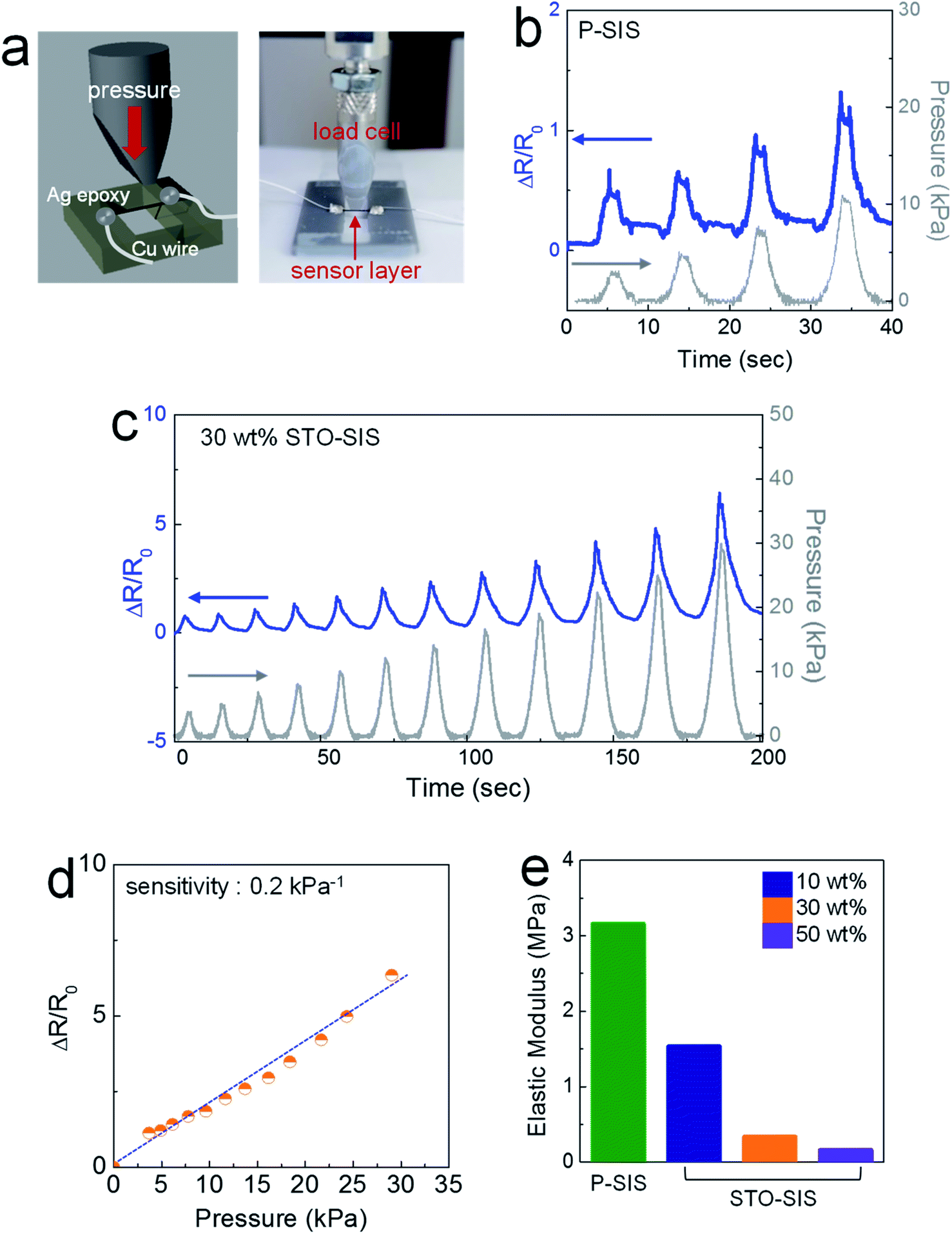 | ||
| Fig. 1 (a) Schematic and photograph showing the measurement procedure of flat pressure sensor devices; resistance signal as a function of pressure level for (b) P-SIS and (c) 30 wt% STO–SIS flat pressure sensor devices. For the case of P-SIS device, over the pressure level of 10 kPa, the abnormal behaviors became severe and a reproducible measurement was hardly obtainable; (d) values in resistance signal depending on the pressure level for 30 wt% STO–SIS flat pressure sensor device; (e) variation in elastic modulus for the P-SIS film and the STO–SIS films with various compositions of STO in SIS elastomer matrix. | ||
Alternatively, other common elastomers, such as polydimethylsiloxane (PDMS) and Ecoflex can be used as an elastomeric matrix. The elastic moduli for PDMS (pre-polymer![[thin space (1/6-em)]](https://www.rsc.org/images/entities/char_2009.gif) :cross-linking agent = 10:1 w/w) and Ecoflex were measured to be 0.7 and 0.04 MPa, respectively. Both PDMS and Ecoflex can be incorporated in the form of pre-polymer (prior to cross-linking reaction); thus, the preparation of highly-viscous composite pastes is much easier without critical troubles in dissolving polymers in a small amount of solvent. However, while the composite paste is prepared and the printing process is carried out, cross-linking reactions proceed at a sluggish reaction rate even at room temperature, and this results in an uncontrollable variation in rheological properties. The rheological properties of thick fluids vary unpredictably depending on the degree of polymerization of surrounding matrix. In addition, even when the sensor devices are prepared from PDMS-based composite pastes, non-ideal behaviors are observed similar to the case of SIS device (Fig. S1†).
:cross-linking agent = 10:1 w/w) and Ecoflex were measured to be 0.7 and 0.04 MPa, respectively. Both PDMS and Ecoflex can be incorporated in the form of pre-polymer (prior to cross-linking reaction); thus, the preparation of highly-viscous composite pastes is much easier without critical troubles in dissolving polymers in a small amount of solvent. However, while the composite paste is prepared and the printing process is carried out, cross-linking reactions proceed at a sluggish reaction rate even at room temperature, and this results in an uncontrollable variation in rheological properties. The rheological properties of thick fluids vary unpredictably depending on the degree of polymerization of surrounding matrix. In addition, even when the sensor devices are prepared from PDMS-based composite pastes, non-ideal behaviors are observed similar to the case of SIS device (Fig. S1†).
It is believed that a reversible transformation of carbon filler networks is manifested more in the STO–SIS elastomeric matrix. In the P-SIS composite layers, both the elastomeric matrix and hybrid carbon network have a hydrophobic nature and interact with each other with low mixing enthalpy; thus, the hybrid carbon fillers are not freely movable with an instant response when the sensor layer is stretched and released repeatedly at a certain level of pressure. The STO, a kind of non-ionic amphiphilic surfactant, can act as a lubricant in an interfacial regime between a hybrid carbon filler and an SIS elastomer. While bulky hydrophobic chains of STO would interact with both hydrophobic constituent materials, a hydrophilic chemical moiety can be positioned between hydrophobic surroundings, preventing direct chemical interaction between a hybrid carbon filler and an elastomeric matrix. When less STO was added with a composition of 10 wt%, non-ideal behaviors were not suppressed completely (Fig. S2a†). When a greater amount of STO was incorporated with a composition of 50 wt%, most non-ideal behaviors vanished with a clear instant response; however, a clear resistance signal was not obtainable at pressure levels over 1.9 kPa due to the insufficient elasticity of the elastomeric matrix (Fig. S2b†). The critical chemical structural role of non-ionic amphiphilic surfactant is clarified with a comparative study using more hydrophilic surfactant, sorbitan monolaurate (SML). The hydrophilic-lipophilic balance (HLB) indexes are 1.8 and 8.6 for STO and SML, respectively. The noisy signals were eliminated to some extent in the SML–SIS sensor (30 wt% SML-added), but the electrical response still did not recover instantaneously to original level when the external pressure was released (Fig. S3†). It is speculated that a sufficient amount of hydrophobic fragments is required along with a presence of hydrophilic segments to allow an intact interaction with the hydrophobic hybrid carbon filler and the elastomeric polymer. When a moderately hydrophobic surfactant, sorbitan monooleate (SMO), with an HLB index of 4.3 was tested as another control experiment, the resistance-signal showed greater improvement than the cases of SML–SIS devices (Fig. S4†).
The sensitivity of the pressure sensor devices was also improved by the addition of STO to the elastomeric matrix. The sensitivities were evaluated to be 0.08 and 0.2 kPa−1 for the P-SIS and STO–SIS devices, respectively. This is attributable to a significant reduction in the elastic modulus of the surfactant-added elastomeric matrix. As seen in Fig. 1e, the elastic modulus decreased significantly as a function of STO composition in the elastomeric matrix. The elastic modulus was measured as 0.34 MPa when the 30 wt%-STO surfactant was added, while the pristine SIS film has an elastic modulus of 3.2 MPa. The use of a softer elastomeric matrix allows for elastic deformation at a higher strain level under a given pressure level, enabling the operation of more sensitive pressure sensor devices. Thermoplastic elastomeric block-copolymers, such as SIS, are generally composed of a soft segment with a low glass transition temperature (Tg) and a hard segment with a high Tg. For the SIS, the glass transition temperatures of polyisoprene and polystyrene are −67 and 100 °C, respectively. When the thermoplastic elastomer is stretched and released, the soft segment, a partially melt phase at room temperature, is extended and recovered.33 Thus, as the fraction of the soft segment increases, the elastic modulus tends to decrease according to the relative composition of the soft segment. For example, the elastic moduli of SIS films with 78, 83, and 86%-isoprene segment are 3.2, 1.1, and 0.8 MPa, respectively (Fig. S5†). It is believed that the addition of a non-ionic surfactant as a non-volatile liquid phase endows more softness to SIS films, acting as another soft segment in thermoplastic polymers. The viscosities of SML and STO are 5349 and 215 cP, respectively (Fig. S6†); thus, it is believed that the incorporation of viscous fluid would allow a more significant reduction in elastic modulus.
The instantaneous reversible response observable in STO–SIS sensors is also attributable to the well-controlled viscoelasticity of the elastomeric matrix. As seen in Fig. 2a, the thermoplastic elastomers with a low elastic modulus suffered from a hysteresis behavior in the stress–strain curve. This indicates that even after tensile stress is released completely, it undergoes an undesirable elongation in the stretching direction. Such a residual elongation recovers in a time-dependent fashion. Because of such a limited property, conductive networks in thermoplastic elastomeric matrix are not transformed reversibly along an either externally applied stress or strain. It is observed clearly that such a viscoelastic property is suppressed efficiently, along with the aforementioned reduction in elastic modulus, by the addition of non-ionic amphiphilic surfactants to thermoplastic elastomers (Fig. 2b and c). The values of dimensional elongation after the first cycle were 3%, 2% and 0% for the P-SIS, SML–SIS, STO–SIS films, respectively. In the cases of P-SIS and SML–SIS films, such irreversible deformation was accumulated with increasing the number of cycling test at a strain level of 0.2, whereas the STO–SIS film exhibited much more improved reversible deformation. The degree of irreversible dimensional elongation was adjustable depending on the composition of surfactant in STO–SIS elastomeric matrix (Fig. 2d). The values in dimensional elongation after the first and tenth cycles were 3% and 2.7% for 10 wt% STO–SIS films, while the dimension was not ever changed even after 10 cycles for 30 and 50 wt% STO–SIS films. The cycling stability of STO–SIS sensor devices is confirmed in Fig. 2e and S7.†
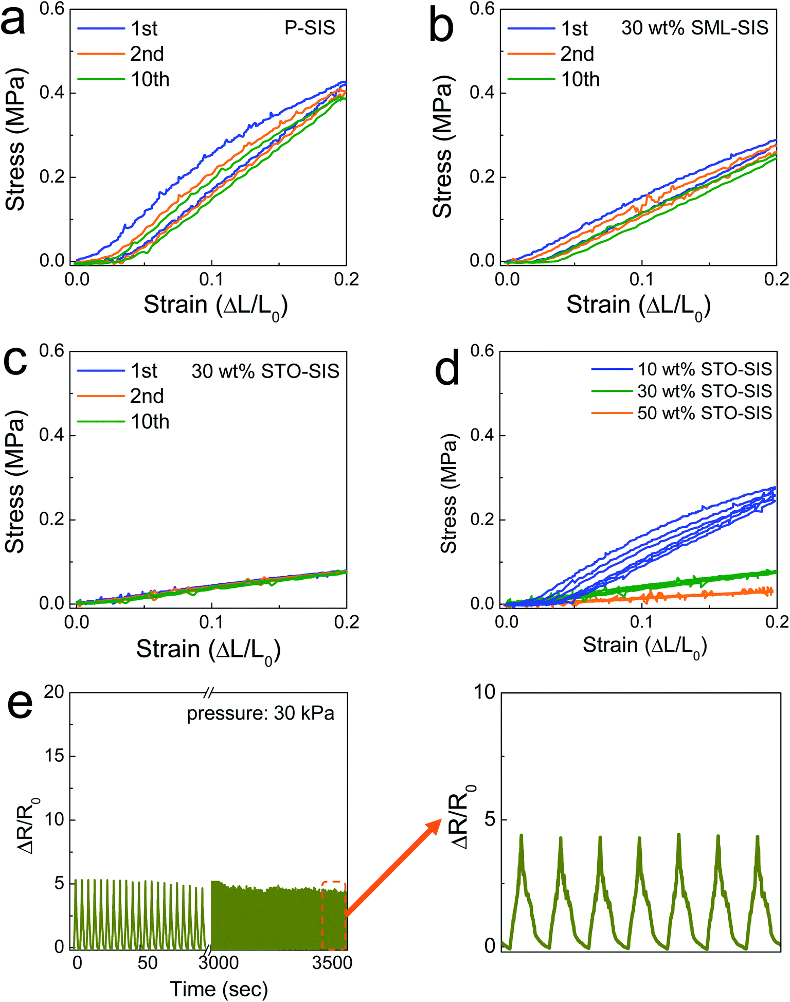 | ||
| Fig. 2 Stress–strain curves in the first, second, and tenth repeated measurements for (a) P-SIS, (b) 30 wt% SML–SIS, (c) 30 wt% STO–SIS, and (d) 10, 30, and 50 wt% STO–SIS films; (e) resistance signal for 792-times repeated measurements at a pressure of 30 kPa for the 30 wt% STO–SIS flat pressure sensor device. | ||
To formulate 3D-printable composite pastes, we regulated the solvent composition to be 46 wt%. The storage modulus of 15613 Pa was measured for the 3D-printable paste (Fig. 3a). It has been reported that a storage modulus over 104 Pa is high enough to maintain printed structures in forming 3D-stackcable architectures.34 As seen in the inset image, the formulated paste did not flow downward according to gravitational force, owing to its thick rheological property. By virtue of its 3D-structural capability, an upright straight line with an aspect ratio of 46.1 was easily formed with a single vertical-movement of the nozzle, and suspended lines were formed in the well with a spacing ranging from 4 to 10 mm (Fig. 3b). The invariant dimension of the suspended printed lines was confirmed by measuring the linewidth at various positions (Fig. S8†). The variation in linewidth was recorded to be 6.3%. In the fabrication of the printed pressure sensor arrays, 3D-printed inter-connection lines and 3D-structured sensor layers were printed on pre-defined PDMS substrates, as seen in Fig. 3c. A mixture of silver flake, SIS, and DCB was used as a printable conductive paste. Ag electrodes were 3D-printed along the side walls of each unit and the bottom surface in pre-defined PDMS substrates (Movie S1†). The insulator for separating inter-bridging inter-connection lines was sequentially printed over Ag electrode lines (Movie S2†). The multi-stack printable insulator paste was formulated from a mixture of SIS and DCB. Overlying inter-connection lines were printed again over the pre-printed insulator parts by adjusting the movement of the nozzle along the z-axis to maintain the nozzle height from either the substrate or the insulator layer (Movie S3†). Uniformity of the electrical conductance was confirmed by the consistency of resistance at each position in the completely printed inter-connection lines (Fig. S9†). Finally, the piezoresistive sensor parts were printed in each unit comprising two straight support lines and the four-layer stacked rectangular pillar structure (Movie S4†). Photographs of the 3D-printed sensor part in one unit and complete pressure sensor arrays are shown in Fig. 3d and e. All printing processes were carried out in air, and all of the printed layers were dried at 80 °C prior to the next printing process.
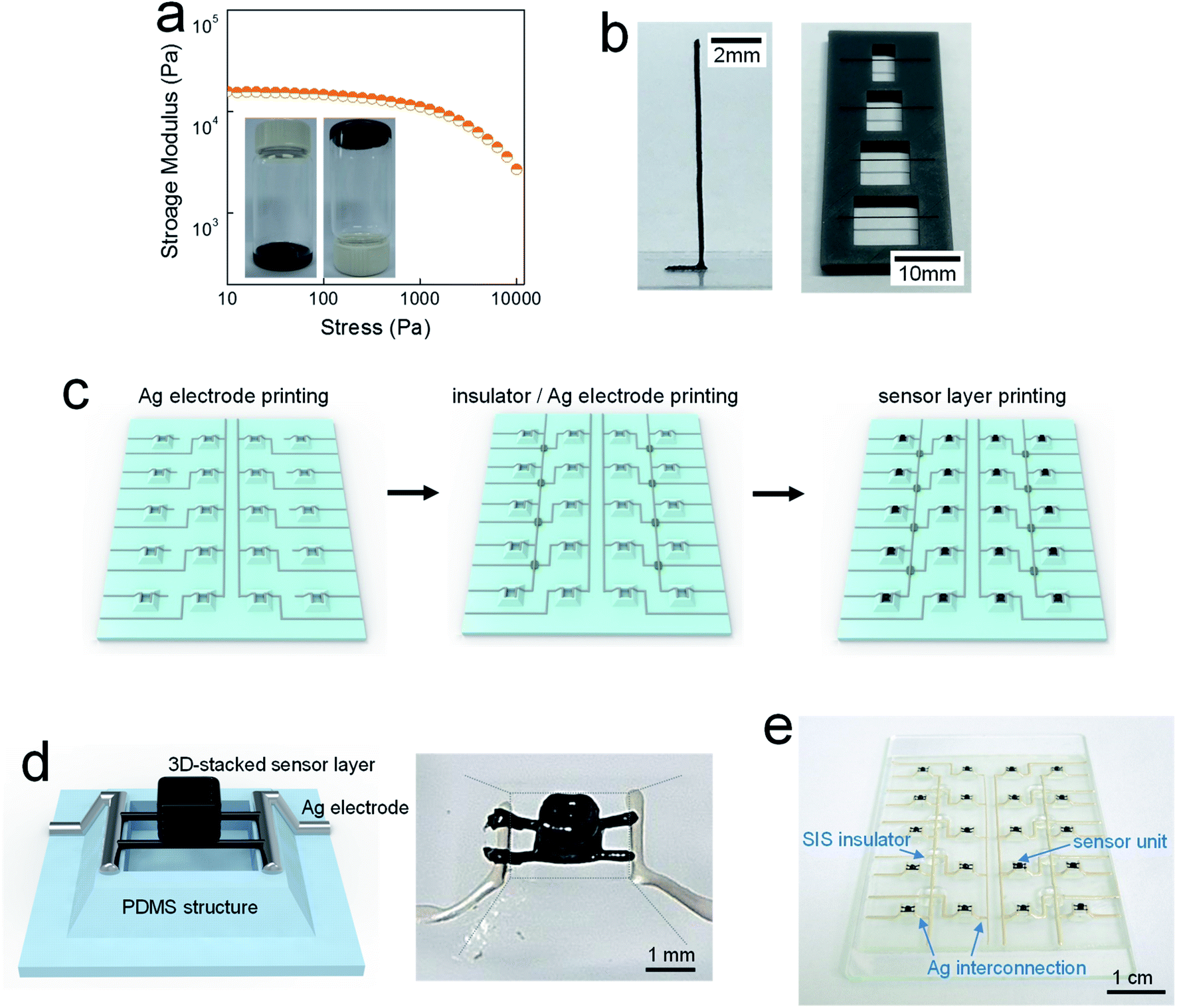 | ||
| Fig. 3 (a) Storage modulus vs. stress curve for 3D-printable piezoresistive composite paste; (b) photographs of upright and suspended structures printed from 3D-printable piezoresistive composite paste; (c) schematic showing sequential printing processes for the fabrication of pressure sensor array device; (d) schematic and photograph of a single unit in 3D-printed array device; (e) photograph of the 3D-printed array device. | ||
For multi-stack printed sensor arrays, a sensitivity of 0.31 kPa−1 was measured at a measurable pressure range up to 30 kPa (Fig. 4a), with an evolution of the signal distinguishable clearly at each pressure level (Fig. 4b). In the pressure sensor devices developed in this study, the electrical signal generation can be adjusted through the variation of architectural factors, such as the height, width, and shape of the pillar structure, in the printed sensor part. Thus, it is believed that the pressure-dependent piezoresistive performance would be improved more with further study for structuring more sensitive sensor layers. The long-term stability was also confirmed through repeated tests at a pressure of 30 kPa (see Fig. S10 and S11, ESI†). To demonstrate the potential of the proposed sensor arrays for practical applications, we placed lightweight objects on a part of units in all-printed pressure sensor arrays. The objects were fabricated by an SLA printing process with weights of 0.78, 4.14, and 8.2 g, which were converted with the values in pressure of 2.1, 11.2, an 22.1 kPa, respectively. As seen in Fig. 4c–e, the resistance signal increased with heavier objects and was measurable clearly on the right position where the objects were placed. As another demonstration, a piece of paper, with a thickness of 0.1 mm and a weight of 0.03 g, was placed on a part of the sensor arrays (Fig. 4f). It was clearly observed that position-addressable resistance signals evolve under a tiny pressure on the specific positions where the paper substrate was located.
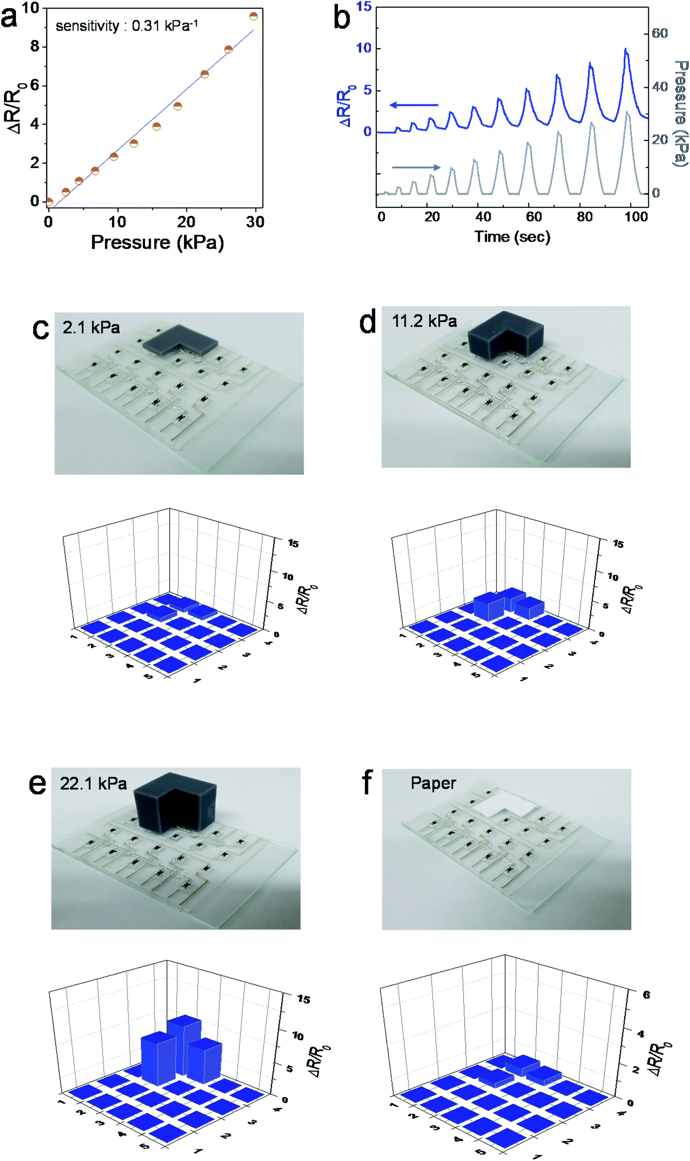 | ||
| Fig. 4 (a) Values in resistance signal and (b) variation in resistance signal as a function of a pressure level in the 3D-printed array device; spatial distribution in resistance signal for the objects with values in pressure of (c) 2.1, (d) 11.2, and (e) 22.1 kPa, and (f) a piece of paper with a weight of 0.03 g. | ||
Conclusions
We formulated the 3D-printable composite pastes for the facile fabrication of piezoresistive pressure sensor arrays. It was revealed that the abnormal behaviors of piezoelectric composite materials can be resolved with the addition of a non-ionic amphiphilic surfactant, sorbitan trioleate, with an HLB value of 1.8. 3D-printed pressure sensor arrays were fabricated by sequential printing of the Ag interconnection line, SIS insulator part, and multi-stacked carbon sensor layer. It was demonstrated that the pressure sensor array exhibits the sensitivity of 0.31 kPa−1 in a linear trend up to a pressure level of 30 kPa, enabling the detection of spatial pressure distribution in the arrays from objects with the weight of 0.03 g and values in pressure from 2.1 to 22.1 kPa.Experimental section
Raw materials
Perylene-3,4,9,10-tetracarboxylic dianhydride (97%, Aldrich), methylene chloride (99.5%, Samchun), triethylamine (99%, Samchun), ethylenediamine (≥99%, Aldrich), multi-walled carbon nanotubes (MWNTs, 97%, length: about ∼1 μm, Applied Carbon Nano Co. Ltd.), toluene (99.5%, Samchun), 1,3-dichlorobenzene (DCB, ≥98.0%, Alfa), Ag flake (SF120, Ames Advanced Materials Corporation), polystyrene-polyisoprene-polystyrene (SIS, styrene 22%, 12 poise @ 25 wt% in toluene, Aldrich), sorbitan trioleate (STO, Showa), sorbitan monooleate (SMO, Showa), sorbitan monolaurate (SML, Showa), and (tridecafluoro-1,1,2,2-tetrahydrooctyl)trichlorosilane (Gelest) were purchased and used as-received without further purification procedures.Synthesis of hybrid carbons as conductive moiety
Graphene oxides (GOs) were synthesized by a modified Hummers' method. For synthesizing amine-functionalized MWNTs (NH2MWNTs), 0.7 g of perylene-3,4,9,10-tetracarboxylic dianhydride (kept overnight in a vacuum at 200 °C prior to use) was mixed with 2.8 g of MWNTs, 700 mL of methylene chloride, 140 mL of triethylamine, and 28 mL of ethylenediamine. Then, the mixture was sonicated for 1 h and stirred vigorously for 24 h. The NH2MWNT samples were dried in a vacuum overnight. The synthesized NH2MWNTs were dispersed in DI water by sonication and then mixed with the GO solution by homogenization. The NH2MWNT/GO ratio was 9 by weight. The carbon hybrid precipitates obtained by centrifugation were dried overnight at 80 °C in a vacuum and then annealed at 400 °C for 2 h under a nitrogen atmosphere.Preparation of 3D-printable piezoresistive sensor pastes
The polystyrene-polyisoprene-polystyrene (SIS) dissolved in 1,3-dichlorobenzene (DCB) was mixed with surfactant, sorbitan trioleate (STO), sorbitan monooleate (SMO), or sorbitan monolaurate (SML). The weight ratio of surfactant/(surfactant + SIS) was regulated to be 0.1, 0.3, and 0.5. The hybrid carbons were mixed with the surfactant-added SIS–DCB solution using a planetary centrifugal mixer (THINKY Mixer, ARE-310). The solid loading of hybrid carbons and SIS in pastes was 43 and 54 wt% for flat and three-dimensionally printed sensor layers, respectively.Preparation of 3D-printable electrode pastes
The Ag flakes were mixed with the polystyrene-polyisoprene-polystyrene (SIS) dissolved in 1,3-dichlorobenzene (DCB), using a planetary centrifugal mixer (THINKY Mixer, ARE-310). The solid loading of Ag flake and SIS was 84 wt%, and the composition ratio of Ag flake/(Ag flake + SIS) was 92 wt%.Fabrication of flat pressure sensor devices
Glass substrates were oxygen-plasma-treated for 5 min and treated chemically to have a hydrophobic surface with (tridecafluoro-1,1,2,2-tetrahydrooctyl)trichlorosilane. Printing was conducted with a 3 axis-programmable dispenser (Image Master 350PC Smart, Musashi). The sensor pastes were printed on hydrophobic-treated glass substrates by a nozzle with an inner diameter of 250 μm. The printed layers were dried at 80 °C for 2 h. The samples were detached from the hydrophobic glass substrates and were placed on pre-defined well structures (fabricated using 3D printer (Form 2, Formlabs)). Both ends of the sensor layers were connected with Cu wire using Ag epoxy resin (CW2400, Chemtronics).Fabrication of 3D-printed pressure sensor arrays
The template was formed using a 3D printer (Form 2, Formlabs) and was treated to have a hydrophobic surface with Teflon release agent (Ease Release® 200, Mann Formulated Products, Inc.). The polydimethylsiloxane (PDMS, Sylgard 184A, a ratio of pre-polymer to cross-linking agent is 10/1 by weight) was poured into the template, followed by a 2-step curing process at 80 °C for 2 h and at 120 °C for 1 h. The resulting PDMS structured-substrates were oxygen-plasma-treated for 20 min. The Ag paste was printed with the 3 axis-programmable dispenser. The inner diameter of the nozzles was 200 μm. The insulator paste, prepared by dissolving the SIS in DCB with a concentration of 32 wt%, was then printed sequentially by the nozzle with an inner diameter of 250 μm. Finally, Ag electrodes were printed to complete the formation of the overall interconnection lines, and then the sensor paste was printed by a nozzle with an inner diameter of 250 μm. The printed layers were dried identically at 80 °C for 2 h. All terminals in the array devices were connected with Cu wires and Ag epoxy resins.Characterization
The electrical signal of the sensor devices was recorded with a digital source meter (2450, Keithley) equipped with a buffer program for high-speed measurement. The stress–strain curves were obtained with a force gauge (M7-2, Mark-10, USA) and a motorized test stand (ESM 303, Mark-10, USA). The rheological properties of the printable pastes were evaluated with a rheometer (MCR 101, Anton Paar).Conflicts of interest
There are no conflicts to declare.Acknowledgements
This research was supported by Global Research Laboratory Program of the National Research Foundation (NRF) funded by Ministry of Science, Information and Communication Technologies and Future Planning (NRF-2015K1A1A2029679), and partially supported by the Nano·Material Technology Development Program through the National Research Foundation of Korea funded by the Ministry of Science, Information and Communication Technologies and Future Planning (NRF-2015M3A7B4050306). This work was also supported by Creative Materials Discovery Program through the National Research Foundation of Korea (NRF) funded by Ministry of Science and ICT (NRF-2019M3D1A2103917) and supported by a grant from Kyung Hee University in 2019 (KHU-20191040).References
- Y. Zang, F. Zhang, C.-A. Di and D. Zhu, Mater. Horiz., 2015, 2, 140–156 RSC
.
- J. Li, J. R. Bao, J. Tao, Y. Peng and C. Pan, J. Mater. Chem. C, 2018, 6, 11878–11892 RSC
- C. M. Boutry, Y. Kaizawa, B. C. Schroeder, A. Chortos, A. Legrand, Z. Wang, J. Chang, P. Fox and Z. Bao, Nat. Electron., 2018, 1, 314–321 CrossRef
- C. M. Boutry, A. Nguyen, Q. O. Lawal, A. Chortos, S. Rondeau-Gagne and Z. Bao, Adv. Mater., 2015, 27, 6954–6961 CrossRef CAS
- J. Kim, M. Lee, H. J. Shim, R. Ghaffari, H. R. Cho, D. Son, Y. H. Jung, M. Soh, C. Choi, S. Jung, C. Choi, S. Jung, K. Chu, D. Jeon, S. T. Lee, J. H. Kim, S. H. Choi, T. Hyeon and D.-H. Kim, Nat. Commun., 2014, 5, 5747 CrossRef CAS
- L. Y. Chen, B. C. Tee, A. L. Chortos, G. Schwartz, V. Tse, D. J. Lipomi, H. S. Wong, M. V. McConnell and Z. Bao, Nat. Commun., 2014, 5, 5028 CrossRef CAS
- C.-C. Kim, H.-H. Lee, K. H. Oh and J.-Y. Sun, Science, 2016, 353, 682–687 CrossRef CAS
- J. Kim, J. Kim, S. Song, S. Zhang, J. Cha, K. Kim, H. Yoon, Y. Jung, K.-W. Paik and S. Jeon, Carbon, 2017, 113, 379 CrossRef CAS
- M. Yang, S. W. Kim, S. Zhang, D. Y. Park, C.-W. Lee, Y.-H. Ko, H. Yang, Y. Xiao, G. Chen and M. Li, J. Mater. Chem. C, 2018, 6, 7207 RSC
- M. L. Jin, S. Park, J.-S. Kim, S. H. Kwon, S. Zhang, M. S. Yoo, S. Jang, H.-J. Koh, S.-Y. Cho, S. Y. Kim, C. W. Ahn, K. Cho, S. G Lee, D. H. Kim and H.-T. Jung, Adv. Mater., 2018, 30, 1706851 CrossRef
- S. Zhang, X. Xu, T. Lim and H. Peng, J. Mater. Sci.: Mater. Electron., 2019, 30, 13855 CrossRef CAS
- J. Wang, J. Jiu, M. Nogi, T. Sugahara, S. Nagao, H. Koga, P. He and K. Suganuma, Nanoscale, 2015, 7, 2926–2932 RSC
- B. C.-K. Tee, A. Chortos, R. R. Dunn, G. Schwartz, E. Eason and Z. Bao, Adv. Funct. Mater., 2014, 24, 5427–5434 CrossRef CAS
- D. Kwon, T.-I. Lee, J. Shim, S. Ryu, M. S. Kim, S. Kim, T.-S. Kim and I. Park, ACS Appl. Mater. Interfaces, 2016, 8, 16922–16931 CrossRef CAS
- C.-L. Choong, M.-B. Shim, B. S. Lee, S. Jeon, D.-S. Ko, T.-H. Kang, J. Bae, S. H. Lee, K.-E. Byun, J. Im, Y. Jeong, C. E. Park, J.-J. Park and U.-I. Chung, Adv. Mater., 2014, 26, 3451–3458 CrossRef CAS PubMed
- S. Lee, A. Reuveny, J. Reeder, S. Lee, H. Jin, Q. Liu, T. Yokota, T. Sekitani, T. Isoyama, Y. Abe, Z. Suo and T. Someya, Nat. Nanotechnol., 2016, 11, 472–478 CrossRef CAS
- S. Jung, J. H. Kim, J. Kim, S. Choi, J. Lee, I. Park, T. Hyeon and D.-H. Kim, Adv. Mater., 2014, 26, 4825–4830 CrossRef CAS
- Y. Lee, J. Park, S. Cho, Y.-E. Shin, H. Lee, J. Kim, J. Myoung, S. Cho, S. Kang, C. Baig and H. Ko, ACS Nano, 2018, 12, 4045–4054 CrossRef CAS PubMed
- Z. Chen, T. Ming, M. M. Goulamaly, H. Yao, D. Nezich, M. Hempel, M. Hofmann and J. Kong, Adv. Funct. Mater., 2016, 26, 5061–5067 CrossRef CAS
- S.-H. Shin, S.-Y. Choi, M. H. Lee and J. Nah, ACS Appl. Mater. Interfaces, 2017, 9, 41099–41103 CrossRef CAS
- X. Chen, K. Parida, J. Wang, J. Xiong, M.-F. Lin, J. Shao and P. S. Lee, ACS Appl. Mater. Interfaces, 2017, 9, 42200–42209 CrossRef CAS PubMed
- C. Pang, G.-Y. Lee, T.-I. Kim, S. M. Kim, H. N. Kim, S.-H. Ahn and K. Y. Suh, Nat. Mater., 2012, 11, 795–801 CrossRef CAS PubMed
- H. Kim, S.-W. Lee, H. Joh, M. Seong, W. S. Lee, M. S. Kang, J. B. Pyo and S. J. Oh, ACS Appl. Mater. Interfaces, 2018, 10, 1389–1398 CrossRef CAS
- K. Sun, H. Ko, H.-H. Park, M. Seong, S.-H. Lee, H. Yi, H. W. Park, T.-I. Kim, C. Pang and H. E. Jeong, Small, 2018, 14, 1803411 CrossRef
- D. H. Ho, R. Song, Q. Sun, W.-H. Park, S. Y. Kim, C. Pang, D. H. Kim, S.-Y. Kim, J. Lee and J. H. Cho, ACS Appl. Mater. Interfaces, 2017, 9, 44678–44686 CrossRef CAS
- C. Chae, J. Kim, J. Y. Kim, S. Ji, S. S. Lee, Y. Kang, Y. Choi, J. Suk and S. Jeong, ACS Appl. Mater. Interfaces, 2018, 10, 4767–4775 CrossRef CAS PubMed
- W. Feng, A. Fujii, M. Ozaki and K. Yoshino, Carbon, 2005, 43, 2501–2507 CrossRef CAS
- J. Y. Kim, S. Ji, S. Jung, B.-H. Ryu, H.-S. Kim, S. S. Lee, Y. Choi and S. Jeong, Nanoscale, 2017, 9, 11035–11046 RSC
- Y. Jo, D. W. Jeong, J.-O. Lee, Y. Choi and S. Jeong, RSC Adv., 2018, 8, 22755–22762 RSC
- M. Amjadi, A. Pichitpajongkit, S. Lee, S. Ryu and I. Park, ACS Nano, 2014, 8, 5154–5163 CrossRef CAS
- M. Amjadi, K.-U. Kyung, I. Park and M. Sitti, Adv. Funct. Mater., 2016, 26, 1678–1698 CrossRef CAS
- H. S. Lee, Y. Jo, J. H. Joo, K. Woo, Z. Zhong, S. Jung, S. Y. Lee, Y. Choi and S. Jeong, ACS Appl. Mater. Interfaces, 2019, 11, 12622 CrossRef CAS
- S. Choi, S. I. Han, D. Kim, T. Hyeon and D.-H. Kim, Chem. Soc. Rev., 2019, 48, 1566–1595 RSC
- Y. Jo, J. Y. Kim, S.-Y. Kim, Y.-H. Seo, K.-S. Jang, S. Y. Lee, S. Jung, B.-H. Ryu, H.-S. Kim, J.-U. Park, Y. Choi and S. Jeong, Nanoscale, 2017, 9, 5072–5084 RSC
Footnotes |
| † Electronic supplementary information (ESI) available. See DOI: 10.1039/c9ra08461d |
| ‡ J. H. Kang and J. Y. Kim contributed equally to this work. |
| This journal is © The Royal Society of Chemistry 2019 |