DOI:
10.1039/C9RA08373A
(Paper)
RSC Adv., 2019,
9, 38597-38603
Effect of extremely high CO2 pressure on the formation of the corrosion film on 13Cr stainless steel
Received
14th October 2019
, Accepted 8th November 2019
First published on 26th November 2019
Abstract
The corrosion behaviors of 13Cr martensitic steel under different CO2 partial pressures (4–28 MPa) were investigated by weight loss tests and surface characterizations. The results show that the corrosion rate of 13Cr steel shows a sharp increase under higher CO2 pressure (28 MPa), which reached approximately 20–180 times as large as those under lower CO2 pressures (4–12 MPa). Under the lower CO2 pressures, a single-layered Cr(OH)3 passive film forms and completely covers the steel surface. However, when the CO2 pressure reaches 28 MPa, a very different corrosion film which contains an inner Cr(OH)3 passive layer and an outer FeCO3 layer forms, and the inner passive layer shows local damage. This phenomenon can be explained by the lower pH (∼2.75) and the higher H2CO3 concentration in the solution under the higher CO2 pressure.
Introduction
CO2 corrosion is becoming a more and more severe concern in the oil and gas industry as a result of the increasing CO2 concentration with numerous oil and gas fields entering the later development period, as well as the wide use of the CO2 enhanced oil recovery (EOR) technique.1–3 Carbon steels (CS) or low alloy steels (LAS), such as J55, N80, P110, 1Cr, 3Cr, and 5Cr, have been widely used for downhole tubing due to their low cost. However, their poor CO2 corrosion resistance has caused a lot of failures and brought huge economic losses. Furthermore, the leakage of oil and gas can also cause great environmental pollution. Corrosion resistant alloys (CRA) including martensitic, ferritic, austenitic and duplex stainless steels, as well as nickel and cobalt alloys and other alloys, will be used in the upstream oil and gas environment when the use of carbon or low alloy steels is not economical due to the presence of either CO2 or H2S.4
Among these CRAs, 13Cr martensitic stainless steel is the most widely used to increase the service life of tubing.5–9 The tubing which serves in a high salinity solution with high-temperatures and high-pressures can undergo severe general corrosion or localized/pitting corrosion.10–15 13Cr stainless steel has been proved to have the good corrosion resistance in CO2 environments as long as the temperature is lower than 150 °C,16 and also a higher strength and a lower cost than the other CRAs such as duplex stainless steels.10,17,18 A lot of researches have studied the corrosion resistance of 13Cr stainless steel and the effect of temperature, chloride ion, and sulphide ion on the passive film stability of 13Cr steel in CO2 environments.11,19–25 However, it is unclear how the presence of CO2 affects the corrosion behaviours of 13Cr stainless steel, particularly the stability of passive films under ultra-high CO2 partial pressures. Do the CO2 act as an inhibitor for the corrosion of 13Cr steel? Or do the extreme high CO2 partial pressures increase the susceptibility of 13Cr steel to localized/pitting corrosion? Several studies have investigated the localized/pitting corrosion mechanism of stainless steel in CO2 environments under the CO2 partial pressures that are not higher than 10 MPa.13,26–30 However, limited studies have reported the relationship between the extremely high partial pressure of CO2 (above 20 MPa), stability of passive film, and pitting corrosion of 13Cr stainless steel.
The objective of this work is to explore the effect of partial pressures of CO2 (up to 28 MPa) on the corrosion of 13Cr stainless steel and clarify how the presence of CO2 affect the stability of passive film under different CO2 partial pressures against pitting corrosion. Scanning electron microscopy (SEM), X-ray diffraction (XRD), quadrant back scattering detector (QBSD), energy dispersive X-ray spectroscopy (EDS), and X-ray photoelectron spectroscopy (XPS) were conducted to investigate the surface and cross-sectional morphology and composition of the corrosion film that forms on the steel surface. A detailed calculation on the pH values and phase concentrations of the test solutions was carried out to investigate the influence of CO2 partial pressures on the stability of passive film and the formation of the corrosion film on 13Cr stainless steel surface in CO2 environments.
Experimental
Weight loss tests
The immersion tests of 13Cr martensitic steel under different CO2 partial pressures were carried out in a 5 L autoclave. The composition of the test solution is listed as follows (mg L−1): 36.3 Ca2+, 10.2 Mg2+, 3838 K+ + Na+, 9008 Cl−, 181.5 SO42−, and 3207 HCO3−. Prior to each test, the specimen was weighed using an analytical balance to get the original weight. After the immersion of 480 h, the corroded specimens extracted from the autoclave were immediately rinsed with absolute ethyl alcohol. The corrosion products were removed according to ASTM G1-03 standard,31 then rinsed, dried, and reweighed to determine the final weight of the specimen. The average corrosion rate was calculated using the following equation.| |
 | (1) |
where Ci is the average corrosion rate, mm per year; W0i and W1i are the original and final weight of specimen, g, respectively; t is immersion time, h; ρ is the density of steel, g cm−3; and S is the exposed surface area in cm2.
Prior to each test, the solution was deaerated and carbonated by bubbling ultrapure CO2 (99.999%) with a flow rate of 100 mL (L−1 min−1) for at least 12 h. Six parallel samples hanged by a glass holder were immersed into the solution as soon as the solution was put into the autoclave. Two more hours of CO2 pure was carried out to remove the oxygen mixed in the process of solution transfer after the autoclave was closed. The immersion tests were performed under 140 °C and different CO2 partial pressures (4 MPa, 8 MPa, 12 MPa, and 28 MPa). The pressure was raised by using a booster pump. The temperature and the pressure simulated the production condition of an oil field in the East China Sea.
Morphology observation and composition analysis
The surface morphology and composition of the corrosion film were investigated by using SEM coupled with EDS, XRD, and XPS using an Al Kα (ht = 1486.6 eV) X-ray source. The cross-sectional morphology was observed by using the QBSD technique.
Electrochemical measurements
The electrochemical characterization was carried out in a homemade 5 L autoclave with the conventional three-electrode system at 140 °C. The 13Cr specimen was used as a working electrode (WE), a platinum sheet was used as a counter electrode (CE), and a high-temperature and high-pressure Ag/AgCl probe was used as a reference electrode (RE). The cyclic potentiodynamic polarization measurements were carried out to investigate the pitting corrosion and passivation behavior at different CO2 pressures. Prior to the cyclic potentiodynamic polarization measurements, the open circuit potential (OCP) was stabilized for at least 1 h. The polarization curves were recorded from −100 mV (vs. OCP) to +1500 mV in the positive direction at a scan rate of 0.5 mV s−1.
Results
Corrosion rates obtained by weight loss tests
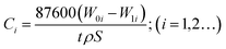
The conclusions section should come in this section at the end of the article. Fig. 1 illustrates that the average corrosion rate is positively correlated to CO2 partial pressure. The corrosion rate is very low (<0.0005 mm per year) and almost no corrosion occurs on 13Cr steel when the CO2 partial pressure is below 12 MPa. When the pressure reaches 28 MPa, the corrosion rate shows a sharp increase and reaches about 0.01 mm a−1, which is approximately 20–180 times as large as those under the lower CO2 partial pressures.
 |
| | Fig. 1 Average corrosion rates of 13Cr stainless steel under different CO2 partial pressures. | |
Morphologies and composition of the corrosion film
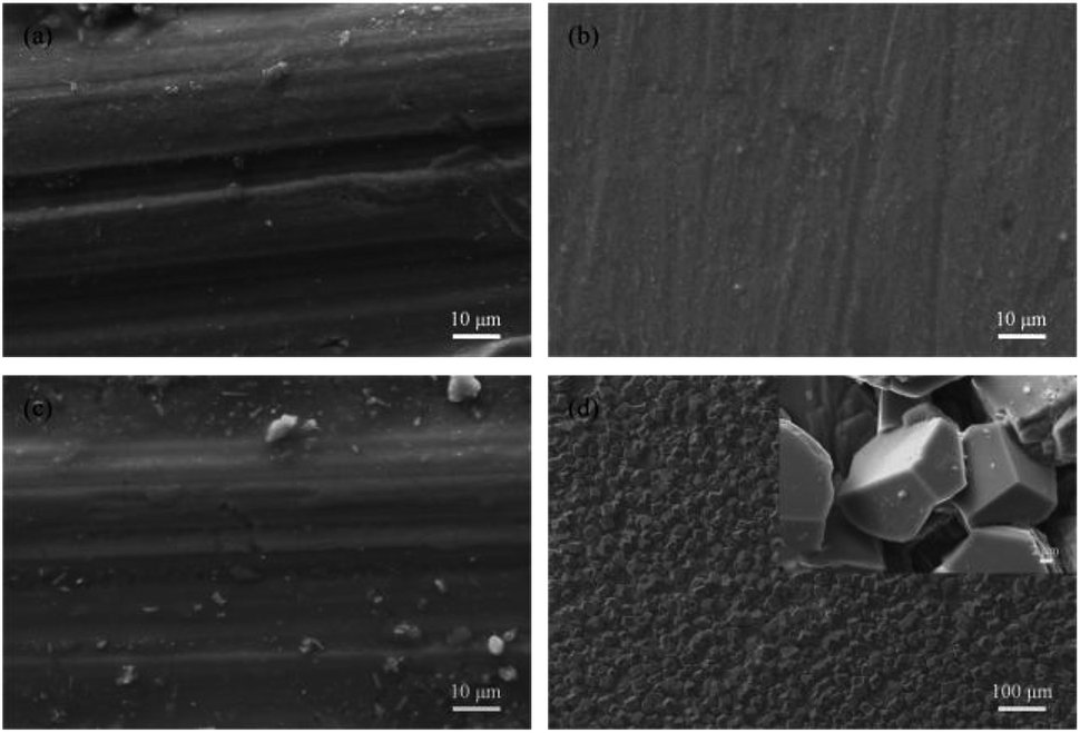
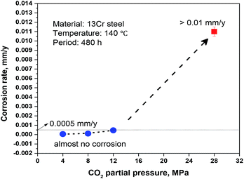
As shown in Fig. 2a, there is no obvious corrosion product on the surface of 13Cr steel after immersion for 480 h under the CO2 pressure of 4 MPa. Even the scratches caused by polish of samples before immersion tests are clearly visible. The corrosion morphology of 13Cr steel under the CO2 pressure of 8 MPa (Fig. 2b) is similar with that under 4 MPa. When the pressure reaches 12 MPa, a few scattered particles start to form on the steel surface as shown in Fig. 2c. If the pressure continues to increase, a large amount of corrosion products which are stacked in grain shape form on the steel surface (Fig. 2d). In the enlarged photograph, these corrosion product particles have a typical crystal characteristic. This type of corrosion film allows corrosive ions pass through, and thus it is less protective than the dense amorphous film.32,33
 |
| | Fig. 2 Surface morphologies of 13Cr stainless steel after an immersion for 480 h in oilfield formation waters under 140 °C and different CO2 partial pressures: (a) 4 MPa; (b) 8 MPa; (c) 12 MPa; (d) 28 MPa. | |
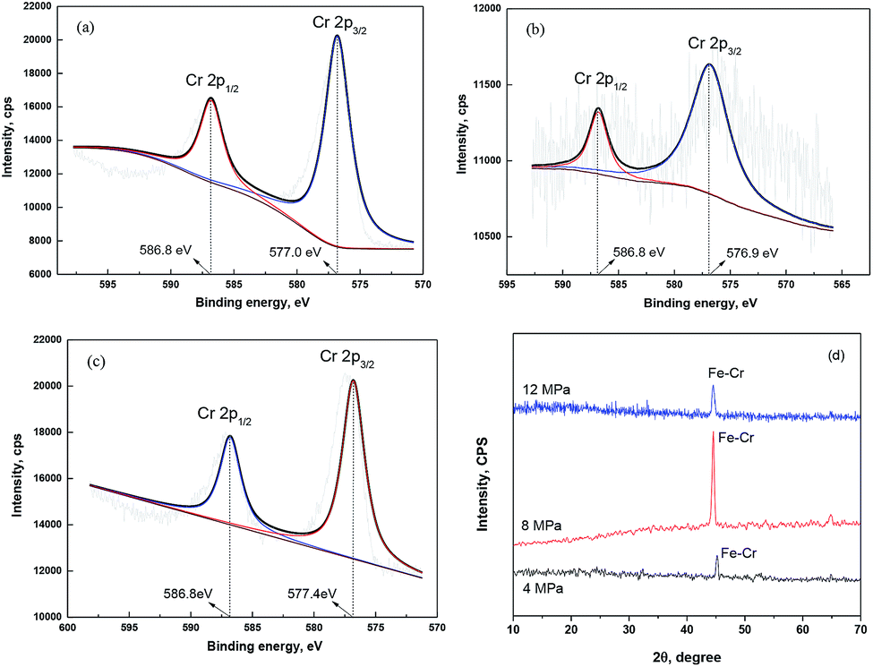
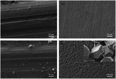
A thin passive film probably forms on the substrate surface. Fig. 3 gives the XPS spectra of Cr 2p signals recorded for the corrosion film that forms on 13Cr steel surface under the lower CO2 partial pressures of below 12 MPa. As shown in Fig. 3a, the Cr 2p spectrum of the corrosion film under 4 MPa is composed of two sets of peaks corresponding to 2p1/2 (586.8 eV) and 2p3/2 (577.0 eV), representing Cr(OH)3.34,35 The Cr 2p spectra of the corrosion film under 8 MPa (Fig. 3b) and 12 MPa (Fig. 3c) are similar with that under 4 MPa, both corresponding to Cr(OH)3. To confirm the state of this Cr(OH)3 film, an XRD investigation was conducted in this section. Fig. 3d shows the XRD spectra of the corrosion film that forms on 13Cr steel surface under the lower CO2 partial pressures of below 12 MPa. As shown in Fig. 3d, only one peak located at 45° is observed in the spectra. This peak is the characteristic spectral lines for Fe–Cr. Moreover, some bulges are found on the spectra, which represent the amorphous state of the corrosion film. In summary, it can be suggested that a thin amorphous Cr(OH)3 passive film forms on the 13Cr steel surface when the CO2 partial pressure is not higher than 12 MPa. Therefore, it shows a very low corrosion rate under the lower CO2 pressures in Fig. 1 as a result of the good protection from the dense amorphous passive film.
 |
| | Fig. 3 XPS (a–c) and XRD (d) spectra of Cr 2p signals recorded for the corrosion film that forms on 13Cr steel surface under different CO2 partial pressures: (a) 4 MPa; (b) 8 MPa; (c) 12 MPa. | |
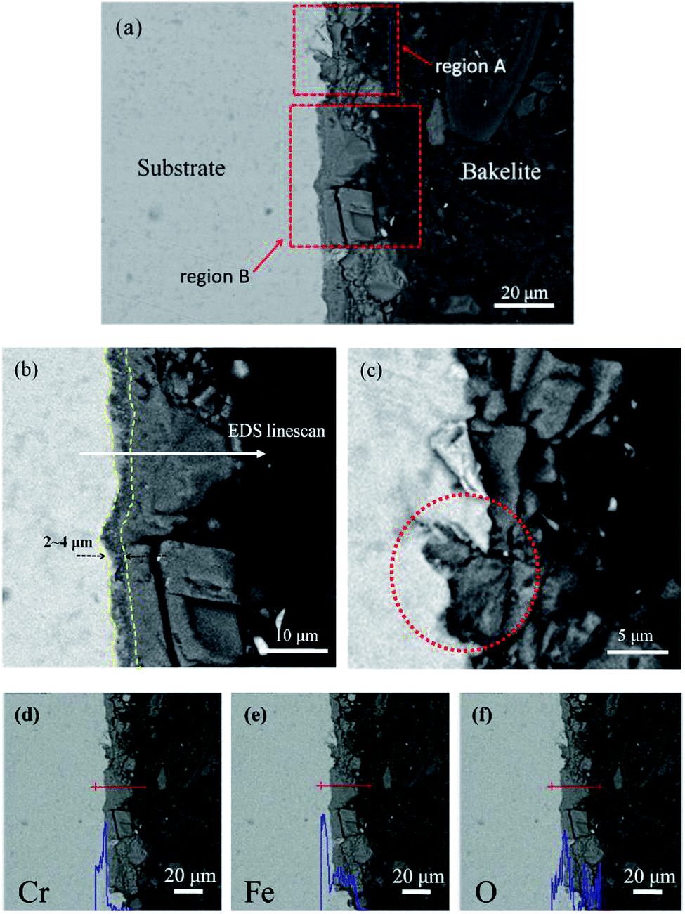
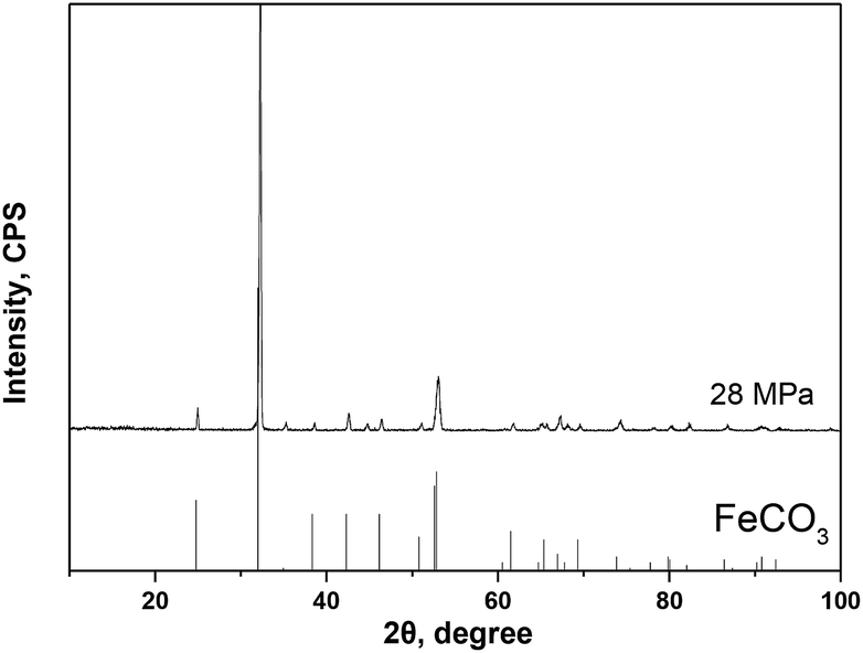
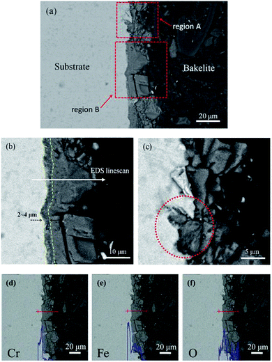
Fig. 4 gives the cross-section morphologies and EDS line scanning analysis of the corrosion film on 13Cr steel surface after an immersion for 480 h in an oilfield formation water under 140 °C and 28 MPa. As shown in Fig. 4a, the corrosion film on substrate surface shows two different regions; region A and region B. In region B (as shown in Fig. 4b), the corrosion film can be divided into two layers; an inner dense layer of about 2–4 μm and an outer porous layer of about 15–20 μm. The EDS line scanning analysis (Fig. 4d) shows that Cr is much enriched in the inner layer. The inner layer mainly consists of Cr and O. The O/Cr atomic ratio is about 2.8, which is nearly 3, indicating that the inner layer is probably Cr(OH)3. In the outer layer, no Cr is found. The O/Fe atomic ratio is about 3, most likely indicating the presence of FeCO3. The XRD result (Fig. 5) on the surface of corrosion film further proves the presence of FeCO3 in the outer layer. In region A, a localized pitting is found on the steel surface as shown in Fig. 4c. This is probably related to the local damage of the inner Cr(OH)3 passive film. As shown in Fig. 4c, only FeCO3 particles cover on the steel surface. Corrosive ions, such as Cl−, can reach to the substrate surface through the gaps between FeCO3 particles. Due to the nonuniformity of the microstructure and composition of the steel substrate, aggressive Cl− leads to the nucleation of pits on the steel surface which is not covered by Cr(OH)3 passive film.36 This type of corrosion film is consistent with that forms on 13Cr stainless steel which serves in field under a high-temperature and high-pressure environment.15
 |
| | Fig. 4 Cross-section morphologies (a–c) and EDS line scanning analysis of Cr (d), Fe (e) and O (f) for corrosion film under 28 MPa. | |
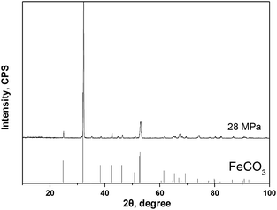 |
| | Fig. 5 XRD spectrum of the corrosion film that forms on 13Cr steel surface at 28 MPa. | |
Cyclic polarization tests
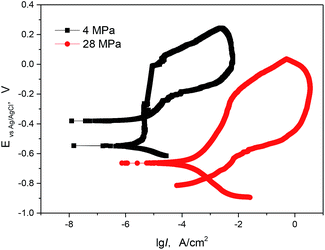
To further understand the pitting and passivation behaviours of 13Cr steel at different conditions. Cyclic polarization measurements were performed in this section. Fig. 6 gives the comparison of cyclic polarization curves of 13 Cr stainless steel at different CO2 partial pressures. From the forward anodic polarization curves, the 13Cr steel shows a stable passivation at 4 MPa, while it tends to become activate at 28 MPa. Both the pitting potential and the open circuit potential decrease with the increasing of CO2 partial pressure. Furthermore, the existence of a hysteresis loop in a cyclic polarization curve indicates a delay in repassivation of an existing pit when the potential is scanned cathodically. The larger the hysteresis loop, the more difficult it becomes to repassivate. In our test, the hysteresis loop at 4 MPa is smaller than that at 28 MPa, and the backward scanning curve intersects the cathodic polarization curve. This indicates that the 13Cr steel is more difficult to repassivate and has the lower pitting resistance at 28 MPa.
 |
| | Fig. 6 Cyclic polarization curves of 13Cr stainless steel in a solution with different CO2 partial pressures at 140 °C. | |
Discussion
Phase equilibrium under different CO2 partial pressures
The corrosion rate of 13Cr steel under the CO2 pressure of 28 MPa is much higher than those under the lower partial pressures. This is related to the incomplete coverage of Cr(OH)3 passive film under 28 MPa as shown in Fig. 4c. To further understand the local damage of the passive film, the pH and different phase concentrations were obtained by phase equilibrium calculation in simulated oil field formation waters under different CO2 partial pressures.
A water chemistry model of a high-temperature and high-pressure CO2-saturated solution (open system) is considered in this study. The main homogenous chemical reactions involved in the simulated formation water in this study can be listed as follows.
| | |
CO2(g) ⇔ CO2(aq) Khen = cCO2(aq)/cCO2(g)
| (2) |
| | |
CO2(aq) + H2O ⇔ H2CO3 Khy = cH2CO3/cCO2(aq)
| (3) |
| | |
H2O ⇔ H+ + OH− Kwa = cH+cOH−
| (4) |
| | |
H2CO3 ⇔ H+ + HCO3− Kca = cH+cHCO3−/cH2CO3
| (5) |
| | |
HCO3− ⇔ H+ + CO32− Kbi = cH+cCO32−/cHCO3−
| (6) |
| | |
CaCO3 ⇔ Ca2+ + CO32− KSP,CaCO3 = cCa2+cCO32−
| (7) |
| | |
MgCO3 ⇔ Mg2+ + CO32− KSP,MgCO3 = cMg2+cCO32−
| (8) |
| | |
FeCO3 ⇔ Fe2+ + CO32− KSP,FeCO3 = cFe2+cCO32−
| (9) |
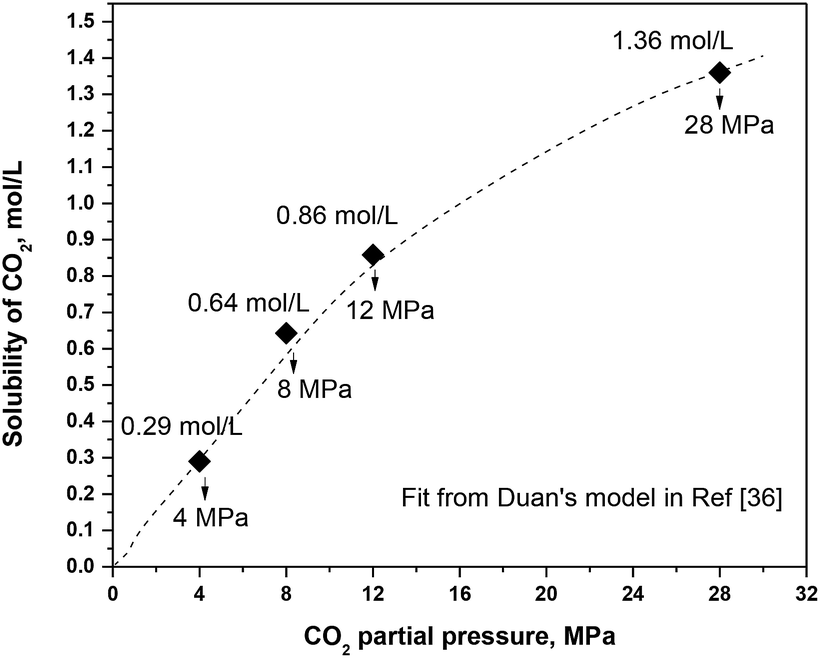
In a high-temperature and high-pressure system, the relationship between the CO2 concentration and pressure is no longer linear. Thus the Henry's law cannot be used. By comparing different models from literatures used for predicting the CO2 solubility in a high-temperature and high-pressure system, Duan's model is chosen in this work to get the CO2 solubility.36 Fig. 7 gives the solubility of CO2 under different CO2 partial pressures.
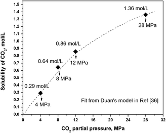 |
| | Fig. 7 Solubility of CO2 under different CO2 partial pressures. | |
The equilibrium constant Khy for carbon dioxide hydration does not change substantially with the temperature increasing and it is independent with pressure. Therefore, Khy can be considered as a constant of 1.67 × 10⁻³. Both the first-order ionization constant (Kca) and second-order ionization constant (Kbi) carbonic acid are the function of temperature and pressure, which can be obtained from the ref. 37.
The other equilibrium constants which include Kwa, Ksp,CaCO3, Ksp,MgCO3, and Ksp,FeCO3, can be obtained by the following equations.38–42
| | |
Kwa = 10−(29.3868−0.0737549×T+7.47881×10⁻⁵×T2)
| (10) |
| | |
Ksp,CaCO3 = 10−7.8156−1502/T+0.03111×T−5.518×lgT
| (11) |
| | |
Ksp,MgCO3 = 107.267−1476.604/T−0.033918×T
| (12) |
| | |
Ksp,FeCO3 = 10175.568−6738.483/T+0.0139×T−67.898×lgT
| (13) |
NaCl, KCl, and NaSO4 completely dissociate in the formation water. The electroneutrality of the solution is independent with these species. Therefore, only the influence of MgCl2, CaCl2, NaHCO3 addition, and the formation of FeCO3 on the hydrolysis equilibrium in CO2 aqueous solutions is considered. The positive and negative charges are equal in the solution, as expressed in eqn (14).
| | |
cNa+ + 2cCa2+ + 2cMg2+ + 2cFe2+ + cH+ = cOH− + cHCO3− + 2cCO32− + cCl−
| (14) |
where
cH+,
cOH−,
cHCO3−,
cCO32−,
cCa2+,
cMg2+, and
cFe2+ are the concentrations of H
+, OH
−, HCO
3−, CO
32−, Ca
2+, Mg
2+, and Fe
2+, respectively.
By joining eqn (4)–(9) and (14), a quartic equation on cH+ can be obtained as follows:
| |
 | (15) |
where
CH2CO3 can be obtained by
eqn (3) and
Fig. 6;
CCl− and
CNa+ are the concentrations of Cl
− and Na
+ from MgCl
2, CaCl
2, and NaHCO
3, having the values of 0.1315 mol L
−1 and 0.009836 mol L
−1, respectively.
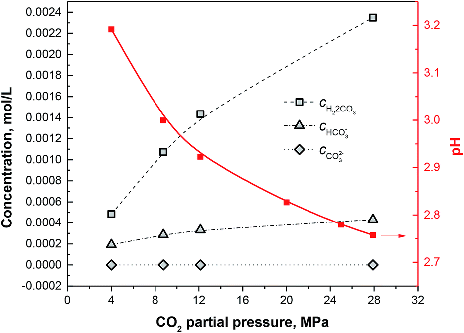
By solving this quartic equation on CH+, the pH values under different CO2 partial pressures can be obtained as shown in Fig. 8. Furthermore, by putting CH+ into eqn (4)–(9), the concentrations of each species can be obtained as shown in Fig. 7.
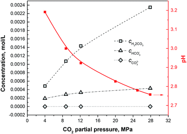 |
| | Fig. 8 Concentrations of H2CO3, HCO3− and CO32− and pH plots under different CO2 partial pressures. | |
The formation mechanism of the corrosion film on 13Cr steel under different CO2 partial pressures
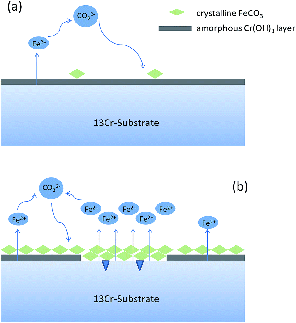
Different from the corrosion under the lower CO2 partial pressures (<12 MPa), a double-layered corrosion film forms on the steel surface when the CO2 partial pressure increases to 28 MPa. A model is proposed for the film formation on the 13Cr steel surface under different CO2 partial pressures. As displayed in Fig. 9a, a single-layered passive film forms and completely covers on the steel surface under the lower CO2 partial pressures. A few scattered FeCO3 particles may forms and deposit on the passive film. The passive film of 13Cr stainless steel mainly consists of Cr(OH)3 which is in amorphous state and could prevent aggressive ions such as Cl− to transfer to the steel substrate. Cr(OH)3 precipitation contributes to the increase of films thickness and inhibits the precipitation of FeCO3. When the CO2 pressure reaches 28 MPa, a much different corrosion film which contains an inner Cr(OH)3 passive layer and an outer FeCO3 layer forms on the steel surface as shown in Fig. 9b. What is more interesting is that the inner passive film shows a local damage and the pitting is found under the damaged area. This phenomenon can be explained by the lower pH and the higher H2CO3 concentration in the solution under the higher CO2 partial pressure. Firstly, Cr(OH)3 is soluble in acid. The lower pH can promote the dissolution of Cr(OH)3 passive film. As shown in Fig. 8, the pH of the solution decreases with the increase of CO2 pressure. The pH under the pressure of 28 MPa is the lowest and reaches about 2.75. Therefore, the Cr(OH)3 passive film has the highest dissolution tendency and is the most unstable under the pressure of 28 MPa. Secondly, H2CO3 has the dihydroxylation effect on the corrosion film, and thus decrease the stability of the passive film.24 The H2CO3 concentration increases with the increase of CO2 partial pressure. The H2CO3 concentration under the pressure of 28 MPa (∼0.00235 mol L−1) is nearly 4 times higher than that under the pressure of 4 MPa (∼0.00048 mol L−1). The higher H2CO3 concentration promotes the dihydroxylation of the passive film and the stability of passive film decreases under the higher CO2 partial pressure.
 |
| | Fig. 9 Schematic diagrams of the corrosion film formation on 13Cr steel surface under different CO2 partial pressures: (a) 4–12 MPa; (b) 28 MPa. | |
In summary, the passive film under the lower pressure (<12 MPa) is stable and protective, thus the corrosion rate keeps at a very low level (see Fig. 1). However, when the pressure increases to 28 MPa, the stability of passive film decreases due to the lower pH and the higher H2CO3 concentration. The passive film is easier to be broken and the aggressive Cl− reaches to the bare steel surface, thus the anodic dissolution of Fe and the nucleation of pits shall be promoted on the steel surface which is not covered by Cr(OH)3 passive film. Moreover, an electrochemical corrosion system with a large cathode and a small anode is established, as shown in Fig. 9b. This will further accelerate the general corrosion and the growth of pit under the damaged area of passive film. Therefore, the corrosion rate shows a sharp increase from 0.00046 mm per year under 12 MPa to 0.011 mm per year under 28 MPa as shown in Fig. 1.
Conclusions
• The 13Cr martensitic stainless steel shows an abrupt change in corrosion resistance if the CO2 partial pressure increases from 12 MPa to 28 MPa. The corrosion rate under the higher CO2 pressure is approximately 20–180 times as large as those under the lower CO2 pressures.
• The stability of the passive film on 13Cr steel surface significantly decreases with the CO2 partial pressure increases to 28 MPa. Under the lower CO2 pressures (<12 MPa), a single-layered Cr(OH)3 passive film forms and completely covers on the steel surface. However, when the CO2 pressure reaches to 28 MPa, a much different corrosion film which contains an inner Cr(OH)3 passive layer and an outer FeCO3 layer forms, and the inner passive layer shows a local damage. This phenomenon can be explained by the lower pH (∼2.75) and the higher H2CO3 concentration in the solution under the higher CO2 pressure. The lower pH and higher H2CO3 concentration can promote the dissolution and dihydroxylation of Cr(OH)3 passive film, respectively.
• The 13Cr steel shows higher pitting tendency under the higher CO2 pressure. This effect is connected with the stability decreasing of passive film. An electrochemical corrosion system with a large cathode and a small anode is established, which will further accelerate the growth of pit under the damaged area of passive film.
Conflicts of interest
There are no conflicts to declare.
Acknowledgements
This work was financially supported by the National Natural Science Foundation of China (no. 51871027) and Fundamental Research Funds for the Central Universities (no. 06500118).
Notes and references
- R. Barker, Y. Hua and A. Neville, Int. Mater. Rev., 2016, 62, 1 CrossRef.
- X. Jiang, Y. G. Zheng, D. R. Qu and W. Ke, Corros. Sci., 2006, 48, 3091 CrossRef CAS.
- C. Sun, J. Sun, Y. Wang, X. Lin, X. Li, X. Cheng and H. Liu, Corros. Sci., 2016, 107, 193 CrossRef CAS.
- H. Höpfner, European Federation of Corrosion Publications No. 17, Maney Publishing, 2nd edn, 2002 Search PubMed.
- H. Marchebois, J. Leyer and B. Orlans-Joliet, in Corrosion 2007, NACE International, 2007, paper no. 07090 Search PubMed.
- H. Marchebois, H. E. Alami, J. Leyer and A. Gateaud, in Corrosion 2009, NACE International, 2009, paper no. 09084 Search PubMed.
- J. Enerhaug, P. E. Kvaale, M. Bjordal, J. M. Drugli and T. Rogne, in Corrosion 1999, NACE International, 1999, paper no. 99587 Search PubMed.
- J. Enerhaug, S. L. Eliassen and P. E. Kvaale, in Corrosion 1997, NACE International, 1997, paper no. 97060 Search PubMed.
- L. J. Mu and W. Z. Zhao, Corros. Sci., 2010, 52, 82 CrossRef CAS.
- H. Y. Ma, Y. S. He, K. Y. Lee and K. S. Shin, Key Eng. Mater., 2017, 727, 29 Search PubMed.
- G. Z. Meng, Y. Li, Y. W. Shao, T. Zhang, Y. Q. Wang and F. H. Wang, J. Mater. Sci. Technol., 2014, 30, 253 CrossRef CAS.
- J. H. Ding, L. Zhang, M. X. Lu, J. Wang, Z. B. Wen and W. H. Hao, Appl. Surf. Sci., 2014, 289, 33 CrossRef CAS.
- S. D. Zhu, J. F. Wei, R. Cai, Z. Q. Bai and G. S. Zhou, Eng. Failure Anal., 2011, 18, 2222 CrossRef CAS.
- Z. Zhang, Y. S. Zheng, J. Li, W. Y. Liu, M. Q. Liu, W. X. Gao and T. H. Shi, Eng. Failure Anal., 2019, 95, 263 CrossRef CAS.
- Y. Long, G. Wu, A. Q. Fu, J. F. Xie, M. F. Zhao, Z. Q. Bai, J. H. Luo and Y. R. Feng, Eng. Failure Anal., 2018, 93, 330 CrossRef CAS.
- Z. F. Yin, X. Z. Wang, L. Liu, J. Q. Wu and Y. Q. Zhang, J. Mater. Eng. Perform., 2011, 20, 1330 CrossRef CAS.
- K. Krishnan, in Corrosion 2017, NACE International, 2017, paper no. 9645 Search PubMed.
- M. D. Pereda, C. A. Gervasi, C. L. Llorente and P. D. Bilmes, Corros. Sci., 2011, 53, 3934 CrossRef CAS.
- X. W. Lei, H. Y. Wang, F. X. Mao, J. P. Zhang, M. F. Zhao, A. Q. Fu, Y. R. Feng and D. D. Macdonald, Corros. Sci., 2018, 131, 164 CrossRef CAS.
- B. W. Luo, J. Zhou, P. P. Bai, S. Q. Zheng, T. An and X. L. Wen, Int. J. Miner., Metall. Mater., 2017, 24, 646 CrossRef CAS.
- X. W. Lei, H. Y. Wang, N. Wang, D. Z. Ren, A. Q. Fu, C. X. Yin, J. P. Zhang, Y. R. Feng and D. D. Macdonald, Appl. Surf. Sci., 2019, 478, 255 CrossRef CAS.
- S. Pahlavan, S. Moazen, I. Taji, K. Saffar, M. Hamrah, M. H. Moayed and S. M. Beidokhti, Corros. Sci., 2016, 112, 233 CrossRef CAS.
- X. C. Han, J. Li, K. Y. Zhao, W. Zhang and J. Su, J. Iron Steel Res. Int., 2013, 20, 74 CrossRef CAS.
- J. Banaś, U. Lelek-Borkowska, B. Mazurkiewicz and W. Solarski, Electrochim. Acta, 2007, 52, 5704 CrossRef.
- H. Y. Li, C. F. Dong, K. Xiao, X. G. Li and P. Zhong, Int. J. Miner., Metall. Mater., 2016, 23, 1286 CrossRef CAS.
- M. Kimura, Y. Miyata, T. Toyooka and Y. Kitahaba, Corrosion, 2001, 57, 433 CrossRef CAS.
- R. D. Kane and J. Burman, in Corrosion 2012, NACE International, 2012, paper no. 1137 Search PubMed.
- Y. Liu, L. N. Xu, M. X. Lu, M. Yao, J. Y. Zhu and L. Zhang, Appl. Surf. Sci., 2014, 314, 768 CrossRef CAS.
- L. Calabrese, L. Bonaccorsi, M. Galeano, E. Proverbio, D. Pietro and F. Cappuccini, Corros. Sci., 2015, 98, 573 CrossRef CAS.
- X. Zhong, S. C. Bali and T. Shoji, Corros. Sci., 2017, 118, 143 CrossRef CAS.
- ASTM G1-03, ASTM, West Conshohocken, PA, 2011 Search PubMed.
- S. Q. Guo, L. N. Xu, L. Zhang, W. Chang and M. X. Lu, Corros. Sci., 2012, 63, 246–258 CrossRef CAS.
- J. Y. Zhu, L. N. Xu and M. X. Lu, Corrosion, 2015, 71, 854 CrossRef CAS.
- W. J. Landis and J. R. Martin, Int. J. Miner. Process., 1994, 42, 251 CrossRef.
- G. S. Frankel, J. Electrochem. Soc., 1998, 145, 2186 CrossRef CAS.
- Z. H. Duan and D. D. Li, Geochim. Cosmochim. Acta, 2008, 72, 5128 CrossRef CAS.
- R. C. Weast, Handbook of chemistry and physics, CRC Press, Florida, 2001 Search PubMed.
- M. Nordsveen, S. Nesic, R. Nyborg and A. Stangeland, Corrosion, 2003, 59, 443 CrossRef CAS.
- G. Dorange, A. Marchand and M. Le Guyader, J. Water Sci., 1990, 3, 261 CAS.
- P. Bénézeth, G. D. Saldi, J. L. Dandurand and J. Schott, Chem. Geol., 2011, 286, 21 CrossRef.
- P. Bénézeth, J. Dandurand and J. Harrichoury, Chem. Geol., 2009, 265, 3 CrossRef.
- X. P. Li, Y. Zhao, W. L. Qi, J. F. Xie, J. D. Wang, B. Liu, G. X. Zeng, T. Zhang and F. H. Wang, Appl. Surf. Sci., 2019, 469, 146 CrossRef CAS.
|
| This journal is © The Royal Society of Chemistry 2019 |
Click here to see how this site uses Cookies. View our privacy policy here. 
 Open Access Article
 This Open Access Article is licensed under a Creative Commons Attribution-Non Commercial 3.0 Unported Licence
 *c
*c