
 Open Access Article
 This Open Access Article is licensed under a Creative Commons Attribution-Non Commercial 3.0 Unported Licence
Synthesis of flowerlike carbon nanosheets from hydrothermally carbonized glucose: an in situ self-generating template strategy†
Yun Chena,
Wenge Qiu *b,
Jiayuan Sunb,
Shining Lib,
Guangmei Baib,
Shenghua Lia,
Chenghui Suna and
Siping Panga
*b,
Jiayuan Sunb,
Shining Lib,
Guangmei Baib,
Shenghua Lia,
Chenghui Suna and
Siping Panga
aSchool of Materials Science & Technology, Beijing Institute of Technology, Beijing 100081, China
bBeijing Key Laboratory for Green Catalysis and Separation, College of Enviromental and Energy Engineering, Beijing University of Technology, Beijing 100124, China. E-mail: qiuwenge@bjut.edu.cn
First published on 15th November 2019
Abstract
A reliable in situ self-generating template strategy has been developed for the synthesis of flowerlike carbon nanosheets by hydrothermal carbonization in the presence of both silica and zinc acetate using glucose as the carbon source. Scanning electron microscopy (SEM), transmission electron microscopy (TEM), atomic force microscopy (AFM), powder X-ray diffraction (XRD), Raman spectroscopy, nitrogen sorption isotherm measurement (BET) and element analysis revealed the morphology, crystal phase structure, porosity and chemical composition. The formation of the zinc silicate nanosheet template was due to the hydrolysis of amorphous silica and self-assembly under hydrothermal conditions. The resulting flowerlike carbon nanosheets proved to be an excellent palladium catalyst support.
1. Introduction
Porous carbon materials have attracted considerable attention in the past decades due to their unique properties including low framework density, large surface area, special microstructure, good chemical inertness and high electrical conductivity. All of these advantages make them potentially promising for application in diverse fields, such as catalysis, environmental treatment, energy storage, advanced electronic devices etc.1–3 Conventional porous carbon materials, such as activated carbon, are usually synthesized through physical or chemical activation processes at elevated temperatures using natural or synthetic raw materials, such as wood, coconut shell, coal or organic polymers, as carbon sources.4,5 It is well known that the pore structure, surface chemical groups and morphology of porous carbon have an important effect on its application performance, so the controlled synthesis of functional carbon materials with special morphology and pore-size is a key point in many fields. Moreover, the properties of the resulting carbon materials also highly depend on the kind of raw material. In order to adjust the intrinsic properties of carbonaceous materials, many novel raw materials have been used, such as task specific ionic liquids,6,7 chiral nematic nanocrystalline cellulose,8 sol–gel polymer,9 graphene,10,11 covalent-organic frameworks,12,13 metal–organic frameworks (MOFs),14,15 and etc. However all these carbon precursors were either costly or difficult to preparation in scale-up. Recently biomass has attracted much attention mainly due to their recyclable, abundantly present and inexpensive. Many kinds of porous carbon had been obtained from saccharides (glucose, sucrose, starch or cellulose),16,17 chitosan,18 bacterial cellulose,19 ovalbumin,20 pomelo peel,21 cicada sloughs,22 wheat straw,23 and cherry stones,24 respectively, by hydrothermal carbonization (HTC) or direct pyrolysis. These processes had the advantages of mild reaction condition, simple operation, low cost, without organic solvent, the carbon products with less ash, and high carbon yield. Wang's group reported a “Leavening strategy” to prepare hierarchically porous carbons (HPCs) from biomass by using gas-producing chemicals during the carbonization process.25 Adding nitrogen containing precursor could offer 3D N-doped HPCs,26 which has an excellent hierarchical nanostructure and showed a high ability in stabilizing and dispersing Ru nanoparticles.Since the discovery of graphene, 2D carbon materials has attracted much attentions due to their many open edges, large surface areas, high chemical stability and conductivity.27 2D porous carbons can be synthesized by templating approaches using graphene oxide (GO),28 metal oxides,29 metal salts,30 and layered inorganic materials31 as templates. A 2D Schiff-base porous polymer has been synthesized through polymerization of melamine and aromatic dialdehyde monomers on GO surface.28 Pyrolysis of this 2D polymer gave a thinner porous carbon nanosheet. Its thickness and surface area can be adjusted by the GO amount in the polymer composite. In addition, porous carbon nanosheets can also be prepared by direct carbonization of biomass precursors including eggplants,32 pistachio shells,33 silk,34 sodium alginate,35 hemp,36 and glucose.37 Recently a one-step procedure has been reported for fabrication 2D porous carbons by direct carbonization of organic salts, such as citrate,38–40 ethylenediamine tetraacetate,41 and gluconate.42 Moreover, Fu and co-workers had successfully prepared porous graphitic carbon nanosheets from cornstalks43 by an in situ self-generating template strategy based on the carburized effect of iron. However, to date, preparation of 2D porous carbon materials with special surface structure and pore-size by a facile strategy and easy scale production is still a challenge.
Herein, we present a new in situ self-generating template strategy for the production of flowerlike carbon nanosheets through hydrothermal carbonization of glucose in the presence of both silica powder and zinc acetate. The morphology and surface structure of the resulting carbon products highly depended on the silica to zinc acetate ratio. The received porous carbon nanosheet has been proved to be an excellent palladium catalyst support for hydrogenolytic debenzylation of tetraacetyldibenzylhexaazaisowurtzitane (TADB),44 in which the N-benzyl groups are difficult to remove.
2. Experimental
2.1. Chemicals
D-Glucose (AR 99.5%) and zinc acetate dihydrate (AR 99.9%) were purchased from Aladdin Chemistry Co. Ltd. Sodium hydroxide, zinc chloride, zinc nitrate hexahydrate and glacial acetic acid were provided by Tianjin Fuchen Chemistry Co. Ltd. PdCl2 (Pd, 59.5%) was purchased from Shanghai Jiuyue Chemical Co., Ltd. HCl (AR 98%) was purchased from Sinopharm Chemical Reagent Beijing Co. Ltd. The commercial activated carbon was purchased from ACROS Organics. SiO2 was received from Chongqing Chemical & Pharmaceutical holding (Group) Company, which was a fine powder product and most of the particle size was under 50 nm (Fig. S1†). TADB was synthesized according to the literature.452.2. Synthesis of porous carbon materials
The porous carbon samples were prepared by hydrothermal treatment using glucose as the carbon precursor in the absence or presence of structure direction additives. Typically, glucose (1.8 g), zinc acetate (8.4 g) and SiO2 (2.1 g) (Zn/Si mass ratio = 4![[thin space (1/6-em)]](https://www.rsc.org/images/entities/char_2009.gif) :1) were added into 25 mL of deionized water. Then, the mixture was put Teflon-lined stainless steel autoclave and heated at 180 °C for 24 h. After cooled down to room temperature, the solid product was recovered by filtration, washed with deionized water and dried in an oven at 120 °C for 4 h. At this stage, the received sample denoted as HT-Glu-4ZnSi, where 4 presented the Zn/Si mass ratio. Subsequently, the above solids were calcinated under N2 flow at 800 °C for 3 h with the heating rate of 10 °C min−1 in a quartz tube furnace. The sample received at this stage denoted as Glu-4ZnSi-T, where T presented the template. The obtained black solids were added to 20 wt% HF solution under stirred for about 6 h and washed with water. Lastly, the porous carbon materials were collected and dried at 100 °C. The received sample now was denoted as Glu-4ZnSi. The samples prepared under a similar procedure in the absence of additive or presence of only silica, or zinc acetate, respectively, were denoted as Glu, Glu-Si, and Glu-Zn.
:1) were added into 25 mL of deionized water. Then, the mixture was put Teflon-lined stainless steel autoclave and heated at 180 °C for 24 h. After cooled down to room temperature, the solid product was recovered by filtration, washed with deionized water and dried in an oven at 120 °C for 4 h. At this stage, the received sample denoted as HT-Glu-4ZnSi, where 4 presented the Zn/Si mass ratio. Subsequently, the above solids were calcinated under N2 flow at 800 °C for 3 h with the heating rate of 10 °C min−1 in a quartz tube furnace. The sample received at this stage denoted as Glu-4ZnSi-T, where T presented the template. The obtained black solids were added to 20 wt% HF solution under stirred for about 6 h and washed with water. Lastly, the porous carbon materials were collected and dried at 100 °C. The received sample now was denoted as Glu-4ZnSi. The samples prepared under a similar procedure in the absence of additive or presence of only silica, or zinc acetate, respectively, were denoted as Glu, Glu-Si, and Glu-Zn.
2.3. Self-assembly of silica and zinc salts
In a typical experiment, zinc acetate dihydrate and SiO2 solid mixture was dispersed in 25 mL deionized water with different Zn/Si mass ratios of 1:1, 2:1, 4:1 and 8:1, respectively. Then, the mixture was poured into a 100 mL Teflon-lined stainless steel autoclave. The hydrothermal synthesis and treatment were conducted under the same condition as the above. The sample prepared with the Zn/Si mass ratios of 1:1, 2:1, 4:1 and 8:1 were denoted as HT-ZnSi, HT-2ZnSi, HT-4ZnSi, and HT-8ZnSi, respectively. “HT-Si”, “HT-Si-ZnCl2” and “HT-Si-Zn(NO3)2” referred to the samples prepared in the absence of zinc salt or presence of ZnCl2 and Zn(NO3)2 with a Zn/Si mass ratio of 4:1, respectively.
2.4. Catalyst preparation
A deposition–precipitation method was employed to fabricate the Pd/C catalysts. Briefly, an appropriate amount of the as-synthesized porous carbon powders (4.0 g) were dispersed in 40 mL deionized water under magnetic stirred. Then PdCl2 (0.34 g) was added, which was dissolved in a diluted HCl solution and heated until the solution turned transparent, suggesting that the H2PdCl4 was formed. After that, the NaOH solution (5 wt%) was added dropwise into the mixture until the pH value of solution up to 10. Along with the addition of sodium hydroxide solution, the pH value of the system increased gradually, leading to the hydrolysis of H2PdCl4 and the formation and deposition of increasing numbers of palladium hydroxide particles on the carbon surface. Up to 10 pH value, almost all the palladium ions were deposited. The catalysts were filtered and washed with deionized water, and dried in oven at 60 °C, finally giving the catalysts with Pd loading of 5 wt%, which were denoted as Pd/Glu-4ZnSi when Glu-4ZnSi was used as the supports. Pd/C (9 wt%) catalyst was prepared under the same procedure using the ACROS Organics activated carbon as the support. Here the palladium loading was increased to 9 wt% because the corresponding Pd/C 5 wt% catalyst showed very low activity for the hydrogenolysis reaction of TADB.2.5. Catalytic performance tests
The catalytic hydrogenolytic debenzylation of TADB was performed in 500 mL vessel. Typically, TADB (30 g), the catalyst (1.26 g), CH3COOH (120 mL), and H2O (30 mL) were added into the reactor. Then the reactor was immediately purged three times with hydrogen. The system was vigorously stirred under H2 at 45 °C for 10 h. After that, the catalyst was filtered and the resulting solution was concentrated under vacuum. Finally, the obtained white solid was washed with ethanol and dried in vacuum oven at 60 °C.2.6. Sample characterization
Scanning electron microscopy (SEM) and transmission electron microscopy (TEM) images of the samples were measured using a JEOL JSM-35C instrument and a JME 2100 (JEOL) microscope, respectively. The textural characteristics and specific area of the samples were measured by physical nitrogen adsorption at 77 K on a Micrometrics, ASAP 2460 analyzer and determined by the Brunauer–Emmett–Teller (BET) method. Meanwhile, the total pore volume was estimated from the adsorption amount of N2 at a relative pressure of P/P0 = ca. 0.99. The pore size distribution was obtained from the nitrogen adsorption data via nonlocal density functional theory (NLDFT). Prior to the measurements, the sample (about 100 mg) was degassed under vacuum at 150 °C for 4 h. The crystal structures of the samples were determined by an X-ray diffractometer (Bruker/AXS D8 Advance) operating at 40 kV and 30 mA using Cu Kα radiation (λ = 0.154 nm). The samples were scanned from 10° to 80° (2θ) with a step size of 0.02° and a scanning rate of 3.5° min−1. Raman spectra was collected at room temperature on a Renishaw 2000 spectrograph with spectral resolution of 2 cm−1. A 532 nm laser was used as the excitation source and the power output was about 40 mW. The Raman signals were collected with conventional 90° geometry and the time for recording each spectrum was about 30 s. AFM images was measured using a Bruker Dimension Icon setup and operated in Peak Force mode. The scan area was 5 μm × 5 μm. The temperature-programmed desorption (TPD) experiment was performed on a chemisorption analyzer (Micromeritics, AutoChem II 2920) combined with a mass spectrometer (HIDEN QGA). First, about 100 mg of the sample was purged in pure He at room temperature for 60 minutes until the baseline remained unchanged. Then, the CO-TPD and CO2-TPD profiles of the sample were obtained by heating the above sample from 30 to 800 °C in a flow of He (40 mL min−1) with a temperature ramp of 10 °C min−1. The concentration of CO and CO2 was monitored by the mass spectrometer. Thermogravimetric analysis (TG) was carried out on a thermal analyzer TA Q600 with a heating rate of 5 °C min−1 in a flowing air (100 mL min−1).3. Results and discussion
3.1. Characterization of the carbon materials
The scanning electron microscope images of the carbon samples prepared by the hydrothermal method using glucose as the carbon source in the absence or presence of structure direction additives, silica, zinc acetate, and both silica and zinc acetate, respectively, are given in Fig. 1. Without additive, only smooth carbon microspheres, which are the typical morphologies of saccharide-based chars,17 were obtained with a diameter of 2–5 μm (Fig. 1a). In the presence of silica, which has been widely used as a hard template in synthesis of nanoporous carbon materials,46 most of the resultant carbon particles in sample Glu-Si were still like spheres (Fig. 1b). However, the particle size reduced significantly possibly due to the nucleation effect of silica pellets. When zinc acetate was added to the glucose solution, the Glu-Zn sample showed an irregular sheet morphology ranging in size from one to a dozen micrometers (Fig. 1c), indicating the strong structure direction of zinc salt.47 Interestingly, as seen in Fig. 1d and e, incorporating silica and zinc acetate resulted in the formation of flowerlike carbon nanosheets with a thickness of about 15 nm.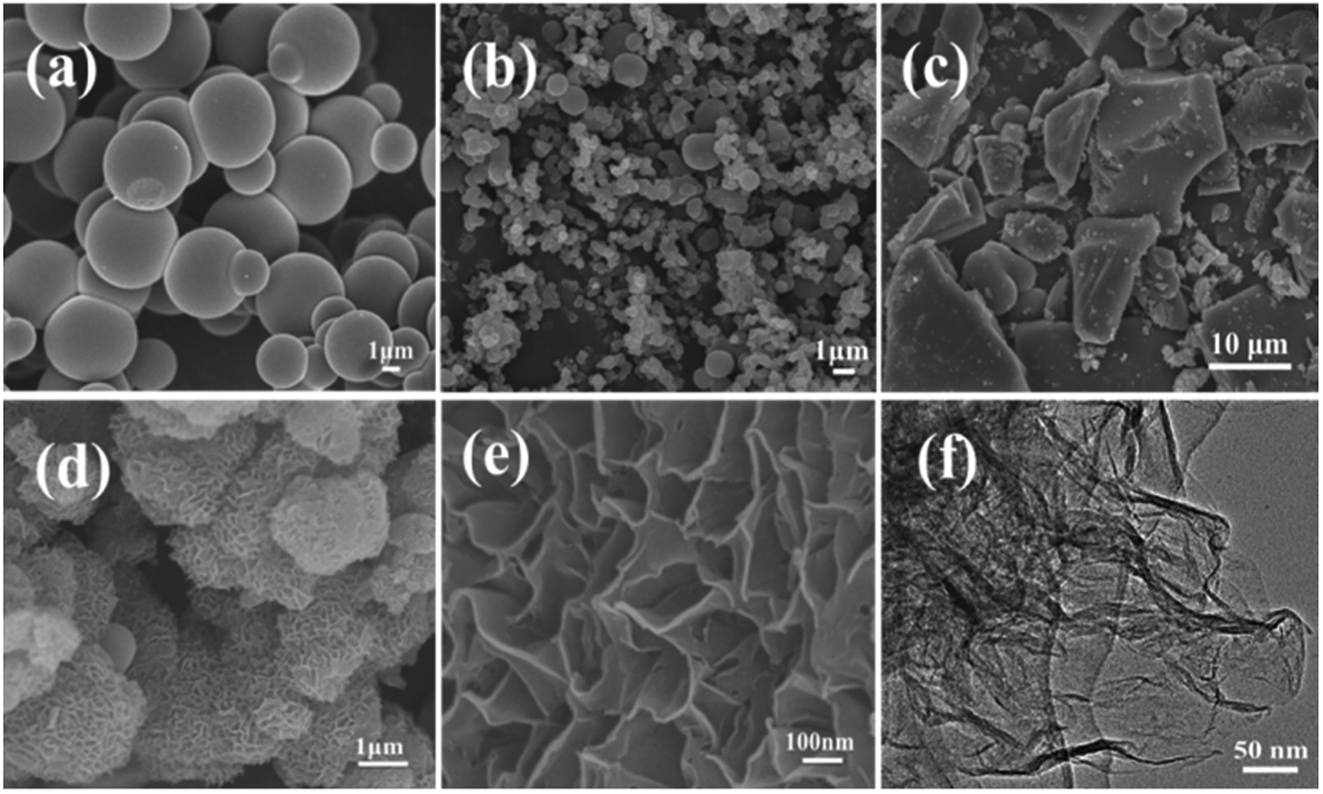 | ||
| Fig. 1 SEM images of Glu (a), Glu-Si (b), Glu-Zn (c), and Glu-4ZnSi (d and e), and TEM image of Glu-4ZnSi (f). | ||
The nanosheet structure of Glu-4ZnSi was further verified by the TEM (Fig. 1f) and AFM images (Fig. 2). From the TEM figure, one could see that the thickness of the carbon sheet in the edge area was much less than 15 nm, implying that the relative thick carbon nanosheet showed in SEM images might be composed by several thin carbon slices. This was confirmed by the AFM data, and a single carbon slice was about 4 nm (Fig. 2).
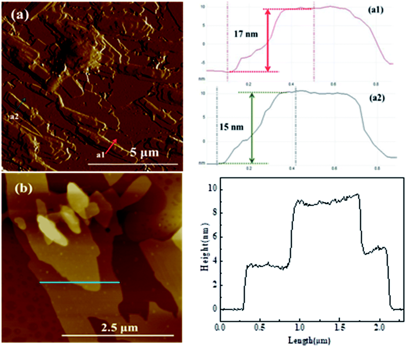 | ||
| Fig. 2 AFM images of the Glu-4ZnSi sample. | ||
The porosities of the as-prepared porous carbons were characterized by N2 adsorption–desorption isotherms (Fig. 3). All the four samples showed relative high specific areas ranging from 419 to 562 m2 g−1 (Table 1). But their pore structures and textural properties were quite different. The adsorption isotherm of Glu exhibited a type I isotherm, suggesting the microporous structure of Glu (Table 1).48 This was also confirmed by its pore-size distribution curve, where only micropores peaks were observed (Fig. S2†). The samples of Glu-Si, Glu-Zn and Glu-4ZnSi all showed a combination of type I and type IV isotherms and type H3 hysteresis loops. Moreover, the appearance of hysteresis loops expanded to much low relative pressure p/p0 values (about 0.2), indicating the existence of inhomogeneous slit channels on the carbon skeleton and the sorption behavior of mesopores (Fig. 3). The pore size distribution (PSD) curves of Glu-Si and Glu-Zn (Fig. S2†) also gave clear information regarding the existence of mesopores between 2 and 30 nm, but the peak intensities were very low, indicating the dominance of micropores. This was consistent with their relative higher Vmic/Vtotal ratio comparing to Glu-4ZnSi. In the adsorption isotherm of Glu-4ZnSi, there was an evident increase of positive slope in the range P/P0 = 0.4–0.9, implying that the mesoporous and macroporous channels had good transport properties. Its pore size distribution (PSD) curve (Fig. S2†) showed several peaks in the range of 0.5–100 nm with the main one centered at about 40 nm, further confirming the existence of mesoporous and macroporous structures from accumulated carbon nanosheets. The Glu-4ZnSi sample had the highest special surface area and pore volume of 562 m2 g−1 and 0.9 cm3 g−1, respectively. This feature of a hierarchical porous structure will has a beneficial effect on catalysis performance since the open channels of mesopores and macropores can accelerate the diffusion of substrates and products.
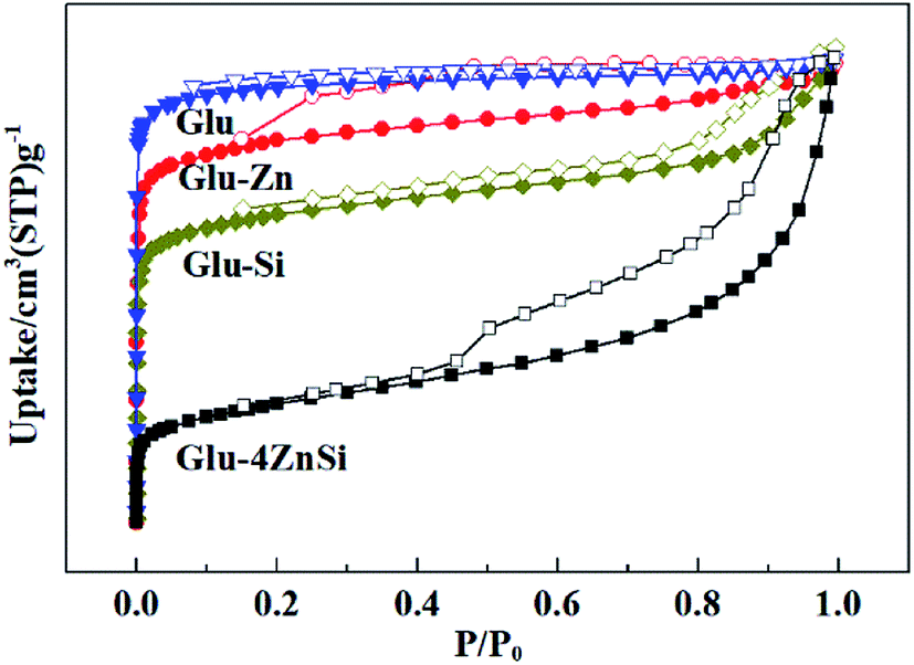 | ||
| Fig. 3 Nitrogen adsorption/desorption isotherms of the carbon materials. | ||
| Samples | SBET/m2 g−1 | Smic/m2 g−1 | Vmic/Vtot | Vtot/cm3 g−1 |
|---|---|---|---|---|
| Glu | 512 | 499 | 0.90 | 0.12 |
| Glu-Zn | 419 | 394 | 0.79 | 0.19 |
| Glu-Si | 471 | 424 | 0.61 | 0.28 |
| Glu-4ZnSi | 562 | 262 | 0.12 | 0.90 |
| ACROS Organics | 702 | 241 | 0.13 | 0.83 |
The crystalline structures of the four samples were characterized by XRD (Fig. S3a†). The presence of two broad diffraction peaks with low intensity at around 2θ = 25° and 44° corresponding to the (002) and (100) diffractions of graphitic carbon (JCPDS no. 41-1487) revealed the relative low degree of graphitization of these porous carbon samples.49 The diffraction intensities of Glu and Glu-4ZnSi at 25° were relatively weaker than that of Glu-Zn, and Glu-Si, implying that the two former samples possessed a higher degree of disorder. In the XRD curves of the four samples, no peak of SiO2 and ZnO was observed. Furthermore, the TG curve (Fig. S4†) showed that the Glu-4ZnSi sample could be pyrolyzed completely, indicating that the residue of additives had been removed thoroughly. Raman spectra were also used to investigate the graphitization degree of the received porous carbon samples (Fig. S3b†). The Raman spectra of Glu, Glu-Si, Glu-Zn, and Glu-4ZnSi showed two peaks at 1340 and 1589 cm−1, knowing as the D and G bands,50 respectively. The D band corresponded to the defects and disordered portions in the carbon materials, and the G band was associated with the ordered sp2 carbon. The calculated ID/IG values of the four samples were similar, indicating the similar graphitization degrees and the coexistence of ordered and disordered carbon species in these carbon products. However, the intensities of D and G bands of Glu were much weaker than the other samples possible due to the presence of more portions of amorphous carbon species.
It is well known that the surface functional groups of activate carbon that formed during preparation or subsequent activation have significant effect on its catalytic performance.51 The TPD spectra of the four various carbon materials are presented in Fig. 4. For the Glu-4ZnSi sample, two obvious CO2 desorption peaks centered at about 190 and 450 °C could be observed, which could be attributed to the decomposition of the carboxylic acid groups and anhydride groups, respectively.52 There was almost no peak in the high temperature range. On contrary, the intensities of CO2 desorption peaks in low temperature range (<500 °C) for the other three samples were very weak, revealing the low density of carboxylic related groups on their surface. Meanwhile, some CO2 desorption peaks above 500 °C could be detected in samples of Glu, Glu-Si and Glu-Zn, which can be assigned to the decomposition of phenol, carbonyl and lactone groups. Fig. 4b displays the TPD spectra of CO of the four carbon supports. The CO desorption curves of the four carbon materials were similar. Only signals in high temperature range were detected, attributing to the decomposition of high stable phenol, lactone and quinonoid groups.53 The element analysis data showed that the oxygen content in Glu-4ZnSi (13.6%) was higher than that of the other three samples (Table S1†), suggesting the presence of more oxygen functional groups, in particular carboxylic based groups. This was in accordance with the data of the TPD. These results indicated that adding both SiO2 and Zn(CH3COO)2 at the same time increased the amount of surface oxygen function groups of the resulted carbon material.
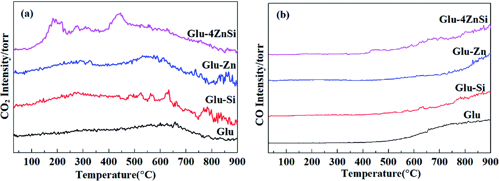 | ||
| Fig. 4 TPD patterns of CO2 (m/z = 44, (a)) and CO (m/z = 28, (b)) for the resultant carbon samples. | ||
3.2. Formation mechanism of the flowerlike carbon nanosheets
In order to understand the formation mechanism of the above mentioned flowerlike carbon nanosheets, the interaction between silica and zinc salt under hydrothermal condition was investigated. It was found that no nanosheet structure formed and the silica particles were almost the same as their initial state with diameter of around 10–30 nm after hydrothermal treatment in the absence of any zinc salt (Fig. S5a†). Adding ZnCl2 or Zn(NO3)2 in system, respectively, also did not change the morphology of the silica (Fig. S5b and c†). The phase structures of the products were also confirmed by XRD data (Fig. S6†), indicating the SiO2 nature. Hydrothermal treatment of zinc acetate only under similar condition gave no solid product. Evaporating this aqueous solution under vacuum provided zinc acetate nano pellets with various sizes (Fig. S5d and S7†). When both zinc acetate and silica were used at the same time with a Zn/Si mass ratio of 1.0, a few piece of nanosheets with 10–30 nm thickness were observed besides the nano particles (Fig. 5a), revealing that the presence of zinc acetate might be the main reason of the nanosheet template formation. Increase the Zn/Si mass ratio leaded to the formation of more nanosheets. When the Zn/Si mass ratio reached to 4, well-defined flowerlike nanosheets were received (Fig. 5c), and there was hardly particle in the product. Further increase the ratio of Zn/Si resulted to thicken of the flakes and the formation of cumulated bulks. These results indicated that the Zn/Si mass ratio had significant effects on the morphology of the resulting silica composite. Qu54 and co-works had also found the effect of the Zn/Si mole ratio on the structure of zinc silicate products, where sodium silicate was used as the silicate precursor. Combining these results, we deduced that the flowerlike carbon nanosheets were formed through an in situ self-generating template strategy. The porous structure of HT-4ZnSi was confirmed by the data of nitrogen sorption isotherms (Fig. S8†), which was quite different from the data of HT-Si (Fig. S9†). Moreover, the adsorption isotherms of HT-4ZnSi, HT-Glu-4ZnSi, and Glu-4ZnSi-T were similar to that of Glu-4ZnSi (Fig. S10†) although their textural properties were different from Glu-4ZnSi due to the existence of template (Table S2†). The result further confirmed an in situ self-generating template process of the flowerlike carbon nanosheets formation. In addition, we treated the Glu-4ZnSi-T sample under air flow at 800 °C for 2 h to remove the carbonous species, giving the self-generated template. Its flowerlike nanosheet morphology and Zn2SiO4 phase structure were demonstrated by the SEM (Fig. S11†) and TEM (Fig. S12†) images and XRD (Fig. S13†) patterns. This gave a direct evidence for the in situ self-generating template process of the flowerlike carbon nanosheets formation.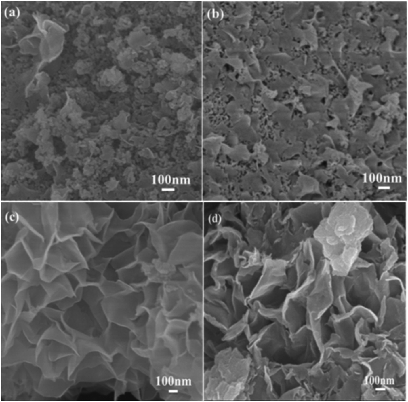 | ||
| Fig. 5 SEM images of HT-ZnSi (a), HT-2ZnSi (b), HT-4ZnSi (c), and HT-8ZnSi (d) composite templates. | ||
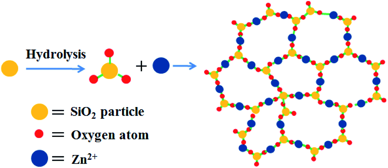
The crystal structure of HT-4ZnSi was investigated by XRD (Fig. S14†). The diffraction peaks at 2θ = 25.4, 31.4 and 33.8° could be attributed to the Willemite (220), (113), and (410) planes diffraction, respectively, which could be well indexed to zinc silicate (JCPDS no. 37-1485),55 indicating the hydrolysis of silica under the hydrothermal condition. Based on the literature56 and the above results, a plausible mechanism of the nanosheet structure formation was outlined in Scheme 1. Under hydrothermal condition, the amorphous silica particles were hydrolyzed on its surface in the presence of a weak base, zinc acetate. Along with the reaction being in progress, more and more silicates were formed, which were connected by zinc ions due to electrostatic interaction affording the zinc silicate nanosheets.
 | ||
| Scheme 1 Mechanism of the zinc silicate nanosheet structure formation. | ||
The proposed mechanism was further demonstrated by the formation of flowerlike carbon nanosheets when the zinc silicate nanosheets (HT-4ZnSi) were used as the hard template directly in hydrothermal carbonization process. However, besides the flowerlike carbon nanosheets, carbon microspheres could be also found in the product, even though the concentration of glucose was reduced by half (Fig. S15†). It was possibly due to the relatively low rate of glucose molecules diffusion into the template channel. However, in the in situ self-generating template process, increasing the glucose concentration to 0.8 or 1.6 mol L−1 still gave the homogeneous flowerlike carbon nanosheets products (Fig. 6). Moreover, their high surface areas and porosity structures were proved by N2 adsorption–desorption data (Fig. S16 and Table S3†). Their crystal structures were similar with Glu-4ZnSi (Fig. S17 and S18†). The results revealed that the in situ self-generating template strategy was better than the traditional hard template method.
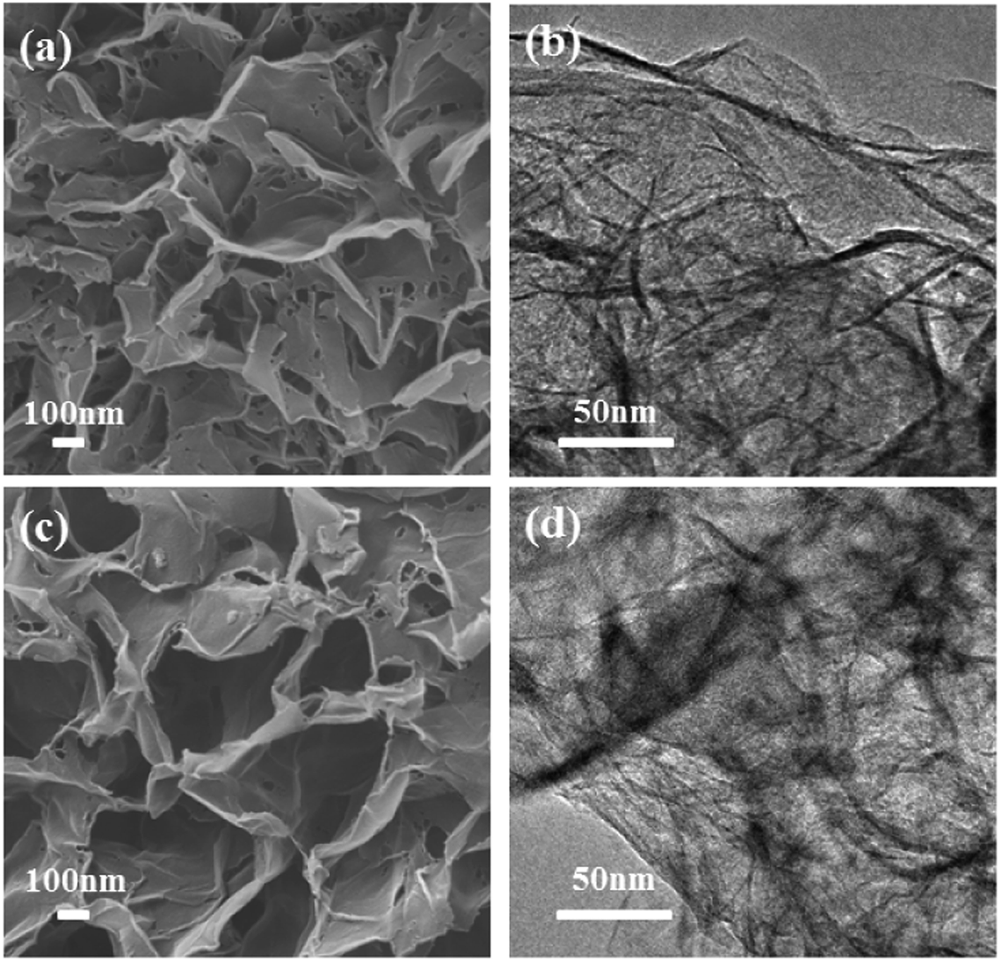 | ||
| Fig. 6 SEM and TEM images of the carbon samples prepared under similar condition with glucose concentrations of 0.8 (a and b), and 1.6 mol L−1 (c and d), respectively. | ||
3.3. Application of the porous carbon materials as palladium catalyst supports
The catalytic activity of Pd/Glu-4ZnSi was evaluated by using the hydrogenolytic debenzylation of TADB as a probe reaction. For comparison, a catalyst that was prepared under similar condition using a commercial activated carbon from ACROS Organics as the support, which had been proved to be a good palladium support in our previous work,57 was also tested (Table 2). As is observed in Fig. 7, the hydrogen consumption rate of Pd/Glu-4ZnSi at the first two hours was much faster than that of Pd/C, and the total hydrogen consumption amount of Pd/Glu-4ZnSi within 10 h was also higher than that of Pd/C, revealing that Pd/Glu-4ZnSi exhibited a higher catalytic activity than the commercial activated carbon supported palladium based catalyst. This was also confirmed by the product yields (Table 2). The above results indicated that the porous carbon nanosheets prepared by the in situ self-generating template strategy was an excellent palladium catalyst support.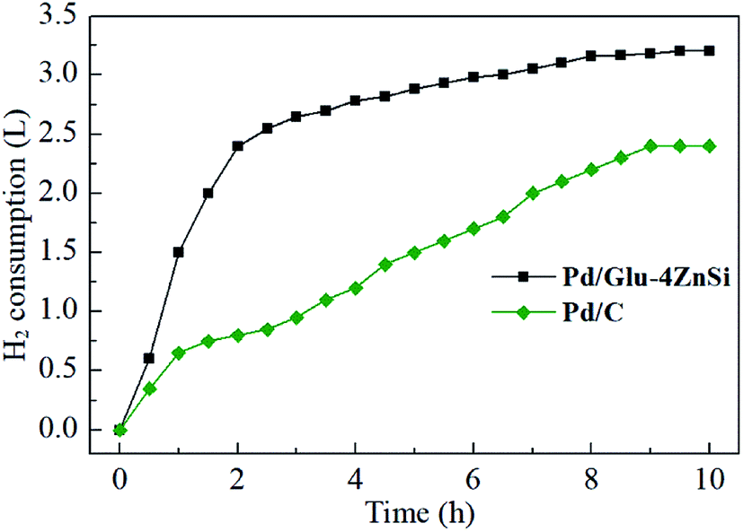 | ||
| Fig. 7 Hydrogen consumption amounts as functions of time during the hydrogenolysis reaction of TADB with Pd/Glu-4ZnSi and Pd/C catalysts. | ||
TEM images of the Pd/Glu-4ZnSi and the Pd/C catalysts (Fig. 8) showed that the palladium species were well dispersed on the surface of the carbon materials. The main Pd particle sizes of Pd/Glu-4ZnSi were in the ranges of <3 nm, which were smaller than that of Pd/C. This was in accordance with the evaluated dispersity data by CO chemisorption (Table S4†). The average sizes of palladium particles on the Pd/Glu-4ZnSi and Pd/C catalysts were 2.40 nm and 3.20 nm, respectively. These results revealed that the palladium species on Glu-4ZnSi surface had a higher dispersity than on the commercial activated carbon, which might be a main factor to dominate the catalytic activity of palladium-based catalyst in the hydrogenolysis reaction. The high dispersity of palladium species on Glu-4ZnSi surface might be related with the intrinsic structure and chemical composition of Glu-4ZnSi. In addition, the relative high pore volume and average pore size of Glu-4ZnSi (Table 1) was also beneficial to the diffusion of substrate and product.
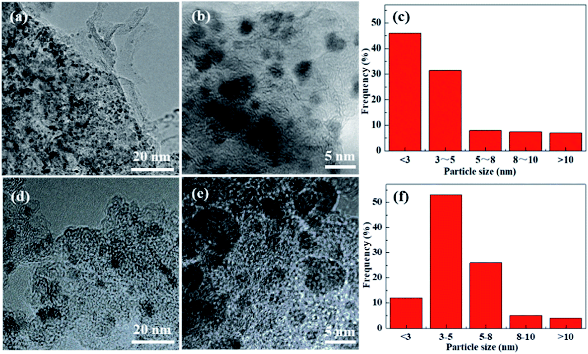 | ||
| Fig. 8 TEM images of Pd/Glu-4ZnSi (a and b) and Pd/C (d and e) samples, and their particle size distributions (c and f). | ||
4. Conclusions
In conclusion, a series of porous carbon materials with various morphologies had been prepared by hydrothermal carbonization in the presence of different structure direction additives using glucose as the carbon source. It could be concluded that we have successfully fabricated flowerlike carbon nanosheets through an in situ self-generating template strategy when both silica and zinc acetate were added at the same time, which could self-organize to form the zinc silicate nanosheet template under hydrothermal condition due to the hydrolysis of amorphous silica. The optimized Zn/Si mass ratio was found to be 4. This work offered a simple process for the preparation of two-dimensional carbon nanosheets, which was proved to be a suitable palladium catalyst support.Conflicts of interest
There are no conflicts to declare.Acknowledgements
We gratefully acknowledge the financial support of the National Natural Science Foundation of China (21577005).References
- M. M. Titirici, R. J. White, N. Brun, V. L. Budarin, D. S. Su, F. del Monte, J. H. Clarkd and M. J. MacLachlan, Chem. Soc. Rev., 2014, 44, 250–290 RSC.
- L. Borchardt, Q. L. Zhu, M. E. Casco, R. Berger, X. Zhuang, S. Kaskel, X. Feng and Q. Xu, Mater. Today, 2017, 20, 592–610 CrossRef CAS.
- M. Inagaki, M. Toyoda, Y. Soneda and T. Morishita, Carbon, 2018, 132, 104–140 CrossRef CAS.
- A. Swiatkowski, Stud. Surf. Sci. Catal., 1999, 123, 69–94 CrossRef.
- C. D. Liang, Z. J. Li and S. Dai, Angew. Chem., Int. Ed., 2008, 47, 3696–3717 CrossRef CAS PubMed.
- J. S. Lee, X. Q. Wang, H. M. Luo, G. A. Baker and S. Dai, J. Am. Chem. Soc., 2009, 131, 4596–4597 CrossRef CAS PubMed.
- I. Fuchs, N. Fechler, M. Antonietti and Y. Mastai, Angew. Chem., Int. Ed., 2016, 55, 408–412 CrossRef CAS PubMed.
- K. E. Shopsowitz, W. Y. Hamad and M. J. MacLachlan, Angew. Chem., 2011, 50, 11183–11187 CrossRef.
- M. Pérez-Cadenas, C. Moreno-Castilla, F. Carrasco-Marín and F. Pérez-Cadenas, Langmuir, 2009, 25, 466–470 CrossRef PubMed.
- X. D. Zhuang, F. Zhang, D. Q. Wu, N. Forler, H. W. Liang, M. Wagner, D. Gehrig, M. R. Hansen, F. Laquai and X. L. Feng, Angew. Chem., Int. Ed., 2013, 52, 9668–9672 CrossRef CAS PubMed.
- D. Krishnan, K. Raidongia, J. Shao and J. Huang, ACS Nano, 2014, 8, 449–457 CrossRef CAS PubMed.
- P. Kuhn, M. Antonietti and A. Thomas, Angew. Chem., Int. Ed., 2008, 47, 3450–3453 CrossRef CAS PubMed.
- C. S. Diercks and O. M. Yaghi, Science, 2017, 355, eaal1585 CrossRef PubMed.
- W. Xia, A. Mahmood, R. Q. Zou and Q. Xu, Energy Environ. Sci., 2015, 8, 1837–1866 RSC.
- K. Shen, X. D. Chen, J. Y. Chen and Y. W. Li, ACS Catal., 2016, 6, 5887–5903 CrossRef CAS.
- A. Jain, R. Balasubramanian and M. P. Srinivasan, Chem. Eng. J., 2016, 283, 789–805 CrossRef CAS.
- Q. Wang, H. Li, L. Q. Chen and X. J. Huang, Carbon, 2001, 39, 2211–2214 CrossRef CAS.
- D. W. Lee, M. H. Jin, D. Oh, S. W. Lee and J. S. Park, ACS Sustainable Chem. Eng., 2017, 5, 9935–9944 CrossRef CAS.
- Y. T. Jiang, J. Yan, X. L. Wu, D. D. Shan, Q. H. Zhou, L. L. Jiang, D. R. Yang and Z. J. Fan, J. Power Sources, 2016, 307, 190–198 CrossRef CAS.
- R. J. White, N. Yoshizawa, M. Antonietti and M. M. Titirici, Green Chem., 2011, 13, 2428–2434 RSC.
- P. P. Zuo, J. Q. Duan, H. L. Fan, S. J. Qu and W. Z. Shen, Appl. Surf. Sci., 2018, 435, 1020–1028 CrossRef CAS.
- X. X. Yang, K. Li, D. M. Cheng, W. L. Pang, J. Q. Lv, X. Y. Chen, H. Y. Zang, X. L. Wu, H. Q. Tan, Y. H. Wang and Y. G. Li, J. Mater. Chem. A, 2018, 6, 7762–7769 RSC.
- W. Liu, J. Mei, G. L. Liu, Q. Kou, T. F. Yi and S. J. Xiao, ACS Sustainable Chem. Eng., 2018, 6, 11595–11605 CrossRef CAS.
- M. Olivares-Marin, J. A. Fernandez, M. J. Lazaro, C. Fernandez-Gonzalez, A. Macias-Garcia, V. Gomez-Serrano, F. Stoeckli and T. A. Centeno, Mater. Chem. Phys., 2009, 114, 323–327 CrossRef CAS.
- J. Deng, T. Y. Xiong, F. Xu, M. Li, C. Han, Y. Gong, H. Wang and Y. Wang, Green Chem., 2015, 17, 4053–4060 RSC.
- M. H. Tang, J. Deng, M. M. Li, X. Li, H. Li, Z. Chen and Y. Wang, Green Chem., 2016, 18, 6082–6090 RSC.
- X. Y. Zheng, J. Y. Luo, W. Lv, D. W. Wang and Q. H. Yang, Adv. Mater., 2015, 27, 5388–5395 CrossRef CAS PubMed.
- X. D. Zhuang, F. Zhang, D. Q. Wu and X. Feng, Adv. Mater., 2014, 26, 3081–3086 CrossRef CAS PubMed.
- Z. J. Fan, Y. Liu, J. Yan, G. Ning, Q. Wang, T. Wei, L. Zhi and F. Wei, Adv. Energy Mater., 2012, 2, 419–424 CrossRef CAS.
- R. R. Song, H. H. Song, J. S. Zhou, X. Chen, B. Wu and H. Y. Yang, J. Mater. Chem., 2012, 22, 12369–12374 RSC.
- X. M. Fan, C. Yu, J. Yang, Z. Ling, C. Hu, M. Zhang and J. Qiu, Adv. Energy Mater., 2015, 5, 1401761 CrossRef.
- Z. J. Li, W. Lv, C. Zhang, B. Li, F. Kang and Q. H. Yang, Carbon, 2015, 92, 11–14 CrossRef CAS.
- J. D. Xu, Q. M. Gao, Y. L. Zhang, Y. Tan, W. Tian, L. Zhu and L. Jiang, Sci. Rep., 2014, 4, 5545 CrossRef CAS PubMed.
- J. H. Hou, C. B. Cao, F. Idrees and X. Ma, ACS Nano, 2015, 9, 2556–2564 CrossRef CAS PubMed.
- H. L. Hu, L. Y. Cao, Z. W. Xu, L. Zhou, J. Li and J. Huang, Mater. Lett., 2016, 185, 530–533 CrossRef CAS.
- H. L. Wang, Z. W. Xu, A. Kohandehghan, Z. Li, K. Cui, X. Tan, T. J. Stephenson, C. K. King'ondu, C. M. B. Holt, B. C. Olsen, J. K. Tak, D. Harfield, A. O. Anyia and D. Mitlin, ACS Nano, 2013, 7, 5131–5141 CrossRef CAS PubMed.
- X. Y. Zheng, W. Lv, Y. Tao, J. Shao, C. Zhang, D. Liu, J. Luo, D. W. Wang and Q. H. Yang, Chem. Mater., 2014, 26, 6896–6903 CrossRef CAS.
- M. Sevilla and A. B. Fuertes, J. Mater. Chem. A, 2013, 87, 13738–13741 RSC.
- W. W. Gao, X. Feng, T. Y. Zhang, H. Huang, J. Li and W. Song, ACS Appl. Mater. Interfaces, 2014, 6, 19109–19117 CrossRef CAS PubMed.
- M. Sevilla and A. B. Fuertes, ACS Nano, 2014, 8, 5069–5078 CrossRef CAS PubMed.
- B. Xu, D. F. Zheng, M. Q. Jia, G. Cao and Y. Yang, Electrochim. Acta, 2013, 98, 176–182 CrossRef CAS.
- A. B. Fuertes and M. Sevilla, ACS Appl. Mater. Interfaces, 2015, 7, 4344–4353 CrossRef CAS PubMed.
- L. Wang, G. Mu, C. G. Tian, L. Sun, W. Zhou, P. Yu, J. Yin and H. Fu, ChemSusChem, 2013, 6, 880–889 CrossRef CAS PubMed.
- K. Dong, Y. Chen, Y. Y. Zhang, C. Sun and S. Pang, J. Energ. Mater., 2017, 35, 421–529 CAS.
- R. B. Wardle, Improved hydrogenolysis of 2,4,6,8,10,12-hexabenzyl-2,4,6,8,10,12-hexaazatetracyclo[5.5.0.05,9.03,11]dodecane, US Pat. 5739325A, 1997.
- J. Lee, S. Han and T. Hyeon, J. Mater. Chem., 2004, 14, 478–486 RSC.
- H. Y. Zhao, X. A. Lu, Y. Wang, B. Sun, X. Wu and H. Lu, J. Mater. Sci., 2017, 52, 10787–10799 CrossRef CAS.
- C. Scherdel and G. Reichenauer, Carbon, 2009, 47, 1102–1111 CrossRef CAS.
- T. Huang, Z. C. Wu, Q. Yu, D. Tan and L. Li, Chem. Eng. J., 2019, 359, 69–78 CrossRef CAS.
- A. Sadezky, H. Muckenhuber, H. Grothe, R. Niessner and U. Poschl, Carbon, 2005, 43, 1731–1742 CrossRef CAS.
- V. Z. Radkevich, T. L. Senko, K. Wilson, L. M. Grishenko, A. N. Zaderko and V. Y. Diyuk, Appl. Catal., A, 2008, 335, 241–251 CrossRef CAS.
- L. Khezami, A. Chetouani, B. Taouk and R. Capart, Powder Technol., 2005, 157, 48–56 CrossRef CAS.
- J. H. Zhou, Z. J. Sui, J. Zhu, P. Li, D. Chen, Y. Dai and W. Yuan, Carbon, 2007, 45, 785–796 CrossRef CAS.
- J. Qu, C. Y. Cao, Y. L. Hong, C. Chen, P. Zhu, W. Song and Z. Wu, J. Mater. Chem., 2012, 22, 3562–3567 RSC.
- X. M. Xu, X. P. Jiang, X. L. Fu, H. Q. Zhan and M. Z. Xu, J. Synth. Cryst., 2014, 43, 3241–3246 CAS.
- B. Chandra Babu and S. Buddhudu, Phys. Procedia, 2013, 49, 128–136 CrossRef.
- W. Qiu, H. Liu, K. Dong, C. Sun, S. Pang, G. Bai, X. Zi, G. Zhang and H. He, Chin. J. Energ. Mater., 2014, 2, 441–446 Search PubMed.
Footnote |
| † Electronic supplementary information (ESI) available. See DOI: 10.1039/c9ra08196h |
| This journal is © The Royal Society of Chemistry 2019 |