DOI:
10.1039/C9RA07999H
(Paper)
RSC Adv., 2019,
9, 37911-37918
Preparation of Cu2O@TiOF2/TiO2 and its photocatalytic degradation of tetracycline hydrochloride wastewater
Received
2nd October 2019
, Accepted 7th November 2019
First published on 21st November 2019
Abstract
A new high-efficiency photocatalyst Cu2O@TiOF2/TiO2 was synthesized by a hydrothermal method and applied to the degradation of tetracycline hydrochloride (TTCH). The samples were analyzed by SEM, EDS, XRD, BET, UV-vis DRS, Raman, PL, FT-IR. The Cu![[thin space (1/6-em)]](https://www.rsc.org/images/entities/char_2009.gif) :Ti = 1:8 catalyst showed a narrow band gap of 2.10 eV, indicating that it can degrade TTCH as a novel photocatalyst capable of responding to sunlight. The average particle diameter is (2–6) nm, and the particle size distribution is narrow. When the reaction was carried out under simulated solar light for 3 hours, the efficiency for degrading 10 mg L−1 tetracycline hydrochloride was as high as 96.83% when the catalyst dosage was 40 mg. It is shown from the capture experiments that ·O2− and ·OH play a major role in this reaction. In addition, it was found that the degradation of TTCH conforms to the first-order kinetic model.
:Ti = 1:8 catalyst showed a narrow band gap of 2.10 eV, indicating that it can degrade TTCH as a novel photocatalyst capable of responding to sunlight. The average particle diameter is (2–6) nm, and the particle size distribution is narrow. When the reaction was carried out under simulated solar light for 3 hours, the efficiency for degrading 10 mg L−1 tetracycline hydrochloride was as high as 96.83% when the catalyst dosage was 40 mg. It is shown from the capture experiments that ·O2− and ·OH play a major role in this reaction. In addition, it was found that the degradation of TTCH conforms to the first-order kinetic model.
Introduction
Organic pollutants with high biological toxicity have attracted the attention of researchers around the world.1 Tetracycline hydrochloride (TTCH) is an antibacterial agent commonly used in human and veterinary medicine.2,3 Tetracycline antibiotics are the second largest class of antibiotics in the world and are used in large quantities.4 Due to the biological toxicity of TC, its metabolites are difficult to degrade in the environment and organism.5,6 The potential hazards of TC and its residues to the water environment have become a problem that cannot be ignored.7 Therefore, methods such as adsorption,8 advanced biological methods,9 membrane filtration10 and ultrasonic induction8 have been developed to solve this problem. However, these methods have disadvantages such as high cost, low efficiency or secondary pollution. Therefore, catalytic technology has become one of the most promising technologies for remediating water pollution and solving environmental problems.11–13 At present, catalysts such as Bi24O31Br10,6 g-C3N4/LaCoO3 (ref. 14) and Pt–TiO2 (ref. 15) have been used to degrade TTCH.
TiO2 has good chemical and biological stability, but it has become a bottleneck for development due to its low light utilization and fast photocarriers recombination.16–19 To change this situation, many studies have enhanced the response of TiO2 in the visible region by doping TiO2 with non-metals (C, N, F, S, etc.)2,20–22 and semiconductors (Cu2O, CdS, etc.).17,23,24 The introduction of F ions can greatly change the performance of TiO2, and titanium oxydifluoride can be formed when TiO2 is in a high concentration of F ions. TiOF2 as a semiconductor material has gradually appeared in the field of photocatalysis. Dong et al.25 synthesized Ag3PO4/TiOF2 by chemical precipitation and degraded methylene blue (MB) under visible light. It was found that TiOF2 can improve the stability of the catalyst system. The novel TiOF2 photocatalyst prepared by Wang et al.26 exhibited certain activity and durability when degrading rhodamine B and 4-chlorophenol under visible light. Studies have shown that TiOF2 can be converted to anatase TiO2 to produce more carriers, and the synergistic effect of the two can improve its photocatalytic performance.27,28 However, there are few studies on TiOF2/TiO2, and it mainly absorbs ultraviolet light.27,29,30
Cu2O is a typical P-type semiconductor with a narrow band gap and has unique visible light driveability,31 which has been extensively studied in the field of photocatalysis. In order to improve the photocatalytic performance, it is often combined with materials such as TiO2,17 reduced graphene oxide,32 Cu2S,33 and CeO2.34 In this paper, the Cu2O@TiOF2/TiO2 photocatalyst was prepared for the first time by hydrothermal method. The Cu2O@TiOF2/TiO2 photocatalyst has a large specific surface area, pores volume and low cost. The catalyst is used for antibiotic wastewater treatment under simulating solar light irradiation by a good combination of adsorption performance and photocatalytic performance, and exhibits excellent degradation effect.
Experimental
Synthesis of the photocatalysts
All chemical reagents are of analytical grade and can be used without purification.
Titanium oxyfluoride (TiOF2) crystals were synthesized by hydrothermal method. 12.5 mL of hydrofluoric acid (HF) was slowly dropped into 34 mL of butyl titanate (C16H36O4Ti, TBT) with stirring, and then 60 mL of glacial acetic acid (C2H4O2) was added dropwise. The mixture was stirred at room temperature for 30 min, transferred to a reaction kettle with a polytetrafluoroethylene liner for 15 h at 160 °C. After the reaction vessel was naturally cooled to room temperature, the solid product was collected by centrifugation. And then it was washed three times with absolute ethanol and pure water, dried under vacuum at 60 °C. The powder obtained was a sample of TiOF2.
Cu2O was prepared by hydrothermal method. 6.3 g of copper sulfate (CuSO4) was dissolved in 100 mL of pure water, and stirred at room temperature for 10 min (solution A). 6.0 g of NaOH was dissolved in 20 mL of pure water. 6.3 g of glucose (C6H12O6) was dissolved in 50 mL of pure water, the solution was heated to 34 °C. The NaOH solution was dropped into the solution A and stirred at a low speed for 5 min. The glucose solution was further added dropwise, and stirred at room temperature for 15 min at room temperature. The mixture was transferred to a reaction vessel of a polytetrafluoroethylene liner and reacted at 90 °C for 4 h. The sample was TiOF2.
Cu2O@TiOF2/TiO2 was prepared by hydrothermal method. 2.0 g of TiOF2 and a certain amount of CuSO4 were dissolved in 100 mL of pure water, and stirred at room temperature for 10 min (solution B). A certain amount of NaOH and glucose and dissolved in 20 mL and 50 mL of pure water, respectively. The glucose solution was heated to 34 °C. The NaOH solution was dropped into the solution B and stirred at a low speed for 5 min. The subsequent steps were the same as the preparation method of Cu2O. According to the relative content of Cu and Ti (ratio of the amount of Cu/Ti substance), the obtained composite was named as Cu:Ti = 1:4, 1:8, 1:10.
Characterization of the samples
The surface morphology and elemental distribution of the samples were analyzed by SEM and corresponding energy dispersive X-ray spectroscopy (EDS) (JSM7500F, Japan). The catalyst crystal characteristics were analyzed using X-ray diffraction (XRD, ICP-XD-2, China) equipped with a Cu-Kα X-ray source (λ = 0.15418 nm). The N2 adsorption–desorption specific surface area analyzer (BET, Micrometrics ASAP2020, USA) was used to analyze the specific surface area and porosity of the catalyst. Fourier transform infrared spectroscopy (FT-IR, Bruker-Tensor 27, Germany) was used to identify the surface functional groups of the catalysts. The absorption characteristics of the samples were measured by UV-visible diffuse absorption spectroscopy (UV-vis DRS, Shimadzu UV-2600, Japan). Raman studies were measured using Raman spectroscopy (Raman, HR800, France) with an excitation wavelength of 532 nm. The photoluminescence spectrum of the photocatalyst was measured by a fluorescence spectrometer (Shimadzu-RF-6000, Japan) with the excitation wavelength was 300 nm.
Photocatalytic activity measurement
Photocatalytic activity was measured by degradation of TTCH. A total of 30 mg of the catalyst was dispersed in a 150 mL double-layered quartz reactor containing 100 ml of a 10 mg L−1 TTCH solution. Cooling water was introduced into the interlayer of the quartz reactor to maintain the solution at room temperature. A Jiguang-500 W Xe lamp (simulating solar light) was located 30 cm away from the TTCH solution. The solution was magnetically stirred for 0.5 h in the dark to obtain the adsorption–desorption equilibrium, before the Xe lamp was turned on to start the degradation. At time intervals of 0.5 h, about 5.0 ml of the solution was extracted and centrifuged at high-speed to remove catalysts. After this, the TTCH concentration was analysed with a Purkinje UV1901 UV-vis spectrophotometer at 355 nm. The photocatalyst was separated from the TTCH solution, before another run was started to investigate the durability of catalysts.
Results and discussion
Characterization results
Morphology and composition characterization. The morphology of Cu2O (a), TiOF2 (b) and Cu:Ti = 1:8 photocatalysts (c) was characterized by SEM. Cu2O is a cubic particle with a diameter of 0.5–1.5 μm. TiOF2 is a cubic structure with a diameter of 300–500 nm, and the surface of the particles is smooth. As can be seen from Fig. 1(c), Cu2O covers the surface of the TiOF2/TiO2 particles. Compared with pure Cu2O, the growth of Cu2O in the composite is limited by the space of TiOF2/TiO2, and the particle size becomes smaller after compounding. Fig. 1(d) shows the EDS spectrum of Cu2O@TiOF2/TiO2. It mainly contains four characteristic peaks of O, F, Cu and Ti. And its content (weight ratio) was 40.04%, 15.9%, 5.79% and 38.26%, respectively, and there were no other impurity peaks.
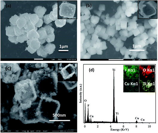 |
| | Fig. 1 SEM image of (a) Cu2O, (b) TiOF2, (c) Cu:Ti = 1:8 Cu2O@TiOF2/TiO2; (d) EDS spectrum of Cu:Ti = 1:8. | |
Crystal structure. The XRD pattern of the sample is shown in Fig. 2. The prepared Cu2O exhibits characteristic peaks at 2θ = 29.62°, 36.68°, 42.67°, 62.47°, 74.94°, and 78.34°, corresponding to the (110), (111), (200), (220), (311), (222) crystal faces of Cu2O (JCPDS no. 65-3288).35 Seven distinct characteristic peaks appear in TiOF2, identical to the standard card of TiOF2 (JCPDS: 08-0060).36 After 4 h of composite reaction, a part of TiOF2 is transformed into TiO2, and there may be a large number of defects at the interface during this phase transition.27,37 Cu:Ti = 1:8 group photocatalysts shows characteristic peaks of TiOF2 at 2θ = 23.43°, 48.55°, 54.42°, 70.12°. Characteristic peaks of Cu2O appear at 2θ = 36.43°, 42.52°, 62.48°, 75.06°, and 79.20°. Characteristic peaks corresponding to the anatase type TiO2 (JCPDS no. 21-1272)38 standard card appeared at 2θ = 25.28° and 38.16°. Therefore, it can be seen that Cu and Ti have been successfully compounded. It can be seen that as the Ti source increases, the characteristic peak of TiOF2 at 2θ = 23.30° gradually appears in the composite catalyst. As the Cu content decreases, the characteristic peak of Cu2O at 2θ = 36.61° is gradually weakened. Furthermore, there are no impurity peaks like copper oxide shown in the patterns, which illustrate the high purity of the prepared cuprous oxide.
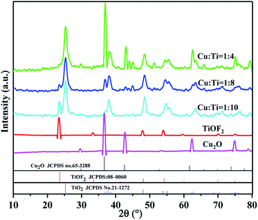 |
| | Fig. 2 XRD patterns of Cu2O@TiOF2/TiO2 photocatalysts with different Cu:Ti. | |
BET surface area analysis. Fig. 3 shows the N2 adsorption–desorption curves for the different ratios of catalysts and the corresponding BJH pore size distribution. It can be seen from the Fig. 3(a) that the catalysts exhibit a typical type IV N2 adsorption curve and a H3 hysteresis regression line, indicating that the catalyst has mesoporous formation.39 According to the pore size distribution of Fig. 3(b), the main pore size of the composite catalyst is distributed at (2–6) nm, indicating that the catalyst has a narrow particle size distribution. The results of the surface area and pores of the catalyst calculated by the BJH method are shown in Table 1, respectively. The surface area and pore volume of Cu2O and TiOF2 are both small. However, the surface area and pore volume of Cu2O@TiOF2/TiO2 increase sharply, and the opening of the hysteresis regression line is larger. It shows that the multi-layer adsorption of the catalyst is stronger and the pore structure is more developed.16 Combined with the SEM image, it is speculated that this is due to the fact that Cu2O is covered on the surface of TiOF2/TiO2, and the particles are loosely packed with each other, forming more gaps and increasing the surface area of the catalyst. In the composite catalyst, the specific surface area and pore volume of Cu:Ti = 1:8 group are optimal, which is more favorable for the adsorption of macromolecular TTCH. Generally, a larger specific surface area, pore volume, and pore size promote absorption of degradants and enhance photocatalytic activity. Therefore, the composite catalyst has the highest photocatalytic activity.
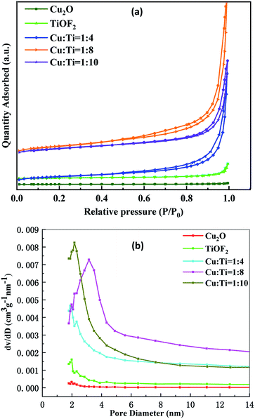 |
| | Fig. 3 (a) Nitrogen adsorption/desorption isotherm; (b) pore size distribution. | |
Table 1 Characteristics of the prepared samples by N2 adsorption–desorption tests
| Sample |
Surface area (m2 g−1) |
Pore volume (cm3(STP) g−1) |
Average pore size (nm) |
| Cu2O |
0.63 |
0.002 |
11.64 |
| TiOF2 |
4.80 |
0.02 |
18.74 |
| Cu:Ti = 1:4 |
26.87 |
0.17 |
23.77 |
| Cu:Ti = 1:8 |
42.31 |
0.24 |
19.80 |
| Cu:Ti = 1:10 |
34.42 |
0.15 |
16.36 |
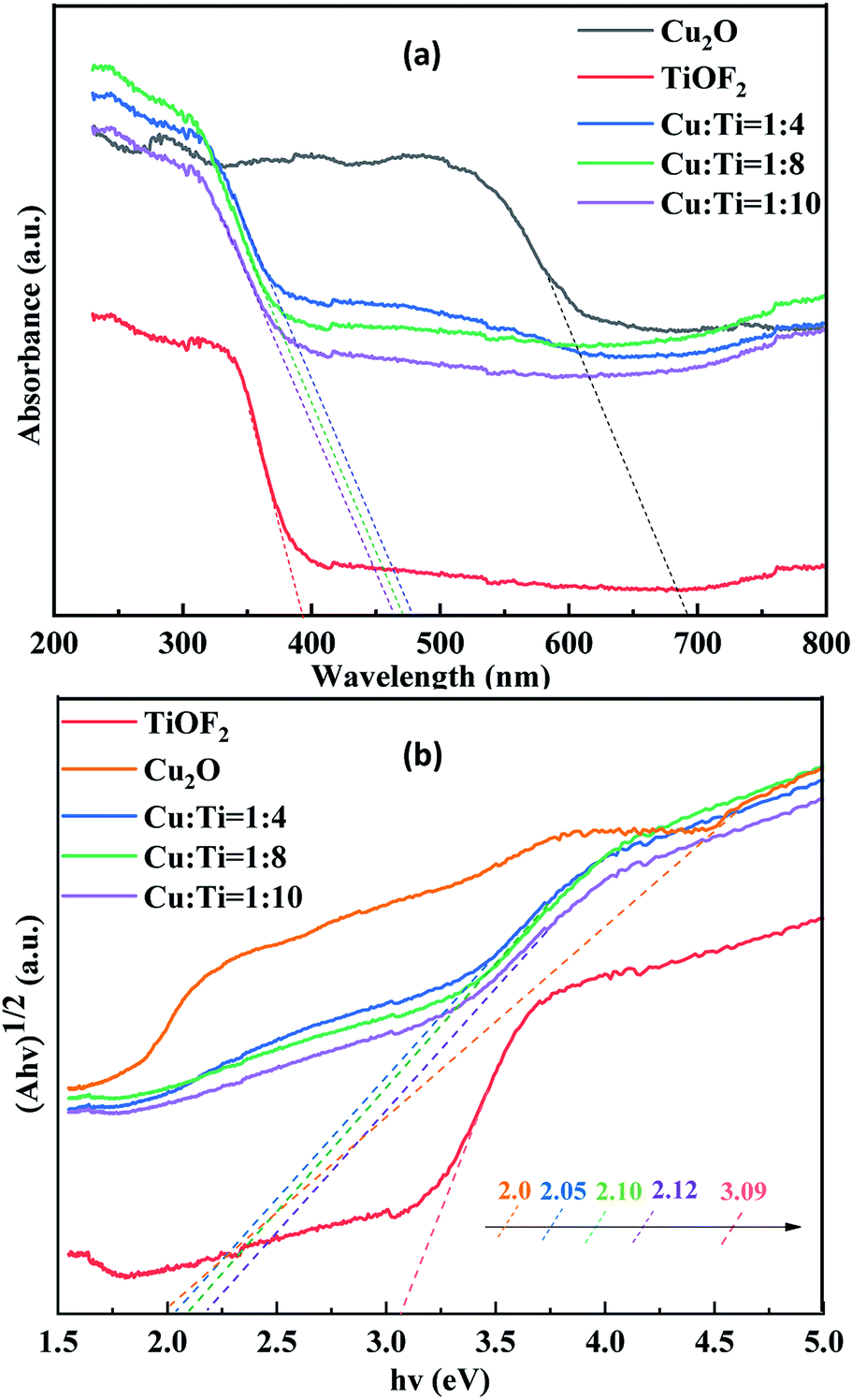
UV-vis DRS analysis. The ultraviolet-visible diffuse reflectance absorptive spectra (UV-vis DRS) are used to characterize the optical absorbance of composites. As shownin Fig. 4, TiOF2 shows an absorption threshold at 394 nm, and the corresponding band gap energy is 3.09 eV. The absorption threshold of Cu:Ti = 1:8 photocatalyst at 474 nm, the corresponding band gap energy is 2.10 eV. It can be seen that the utilization of simulating solar light by the composite catalyst is greatly improved. The composite catalyst shows different degrees of red shift, indicating that its has a significantly enhanced response to simulating solar light, which may be due to the formation of more electron–hole pairs.40 With the decrease of Ti source, the absorption intensity of the composite catalyst increases gradually, indicating that the doping of Cu2O is the key factor to improve the forbidden bandwidth of the catalyst. This is attributed to the synergistic light absorption of Cu2O and TiO2.23 Additionally, the multiple reflections and scattering of light within the porous structure of Cu2O@TiOF2/TiO2 is favorable to reinforce the Interaction between photons and catalyst, enhancing the light absorption of the catalyst. Therefore, the composite catalyst exhibits excellent photocatalytic activity upon degradation of TTCH.
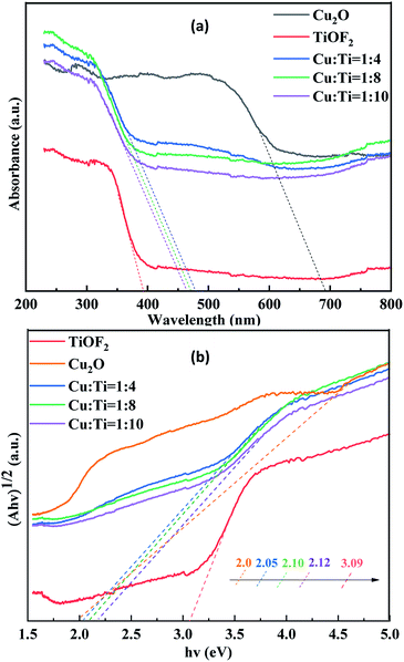 |
| | Fig. 4 UV-vis DRS spectrum (a) and band gap energy (b) of Cu2O, TiOF2 and Cu:Ti = 1:x (x = 4, 8, 10) with different Ti(x) molar ratios. | |
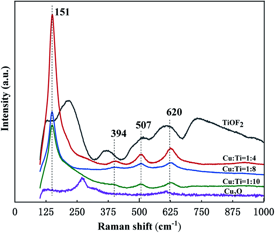
Raman analysis. Fig. 6 shows the Raman spectra of the catalyst prepared. The Raman peak corresponding to anatase are observed at (151507) cm−1 of the composite catalyst.42 The proportion of TiO2 in the composite is large, which is consistent with the XRD results. The composite catalyst corresponds to the Raman peak of TiOF2 at 394 cm−1.43 620 cm−1 corresponds to the characteristic peak of Cu2O, which is an infrared activity mode and can be assigned to the Γ15 mode excited by oxygen deficiency.44 The change trend of the Raman peak of the composite catalyst is similar to that of the XRD pattern, and decreases with the increase of the Ti source. This result further confirmed the structure of Cu2O@TiOF2/TiO2.
 |
| | Fig. 6 Raman spectra of different proportions of photocatalysts. | |
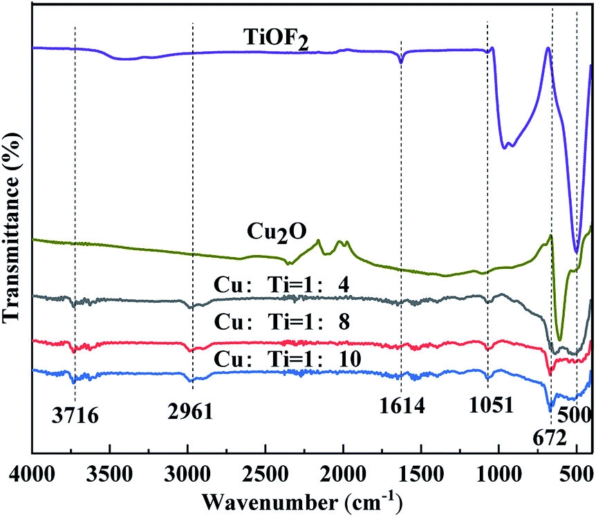
FT-IR analysis. To further characterize the structure of Cu2O@TiOF2/TiO2, analysis was performed using FT-IR. As shown in Fig. 7, the absorption peaks around 3716 cm−1 and 1614 cm−1 are attributed to the stretching vibration and bending vibration of O–H, and the water molecules absorbed by the catalyst surface.45–47 The appearance of an absorption peak near 2961 cm−1 is caused by a hydrogen bond formed by the intermolecular association of hydroxyl groups.48 The absorption peaks around 1051 cm−1 and 500 cm−1 are due to the stretching vibration of the Ti–O group.49 The absorption peak near 672 cm−1 is due to the stretching vibration of the Cu–O bond,50 thereby confirming the successful recombination of Cu and Ti.
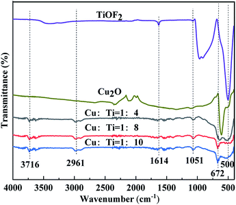 |
| | Fig. 7 FT-IR spectra of Cu2O, TiOF2 and Cu:Ti = 1:x (x = 4, 8, 10) with different Ti(x) molar ratios. | |
Photocatalytic performance
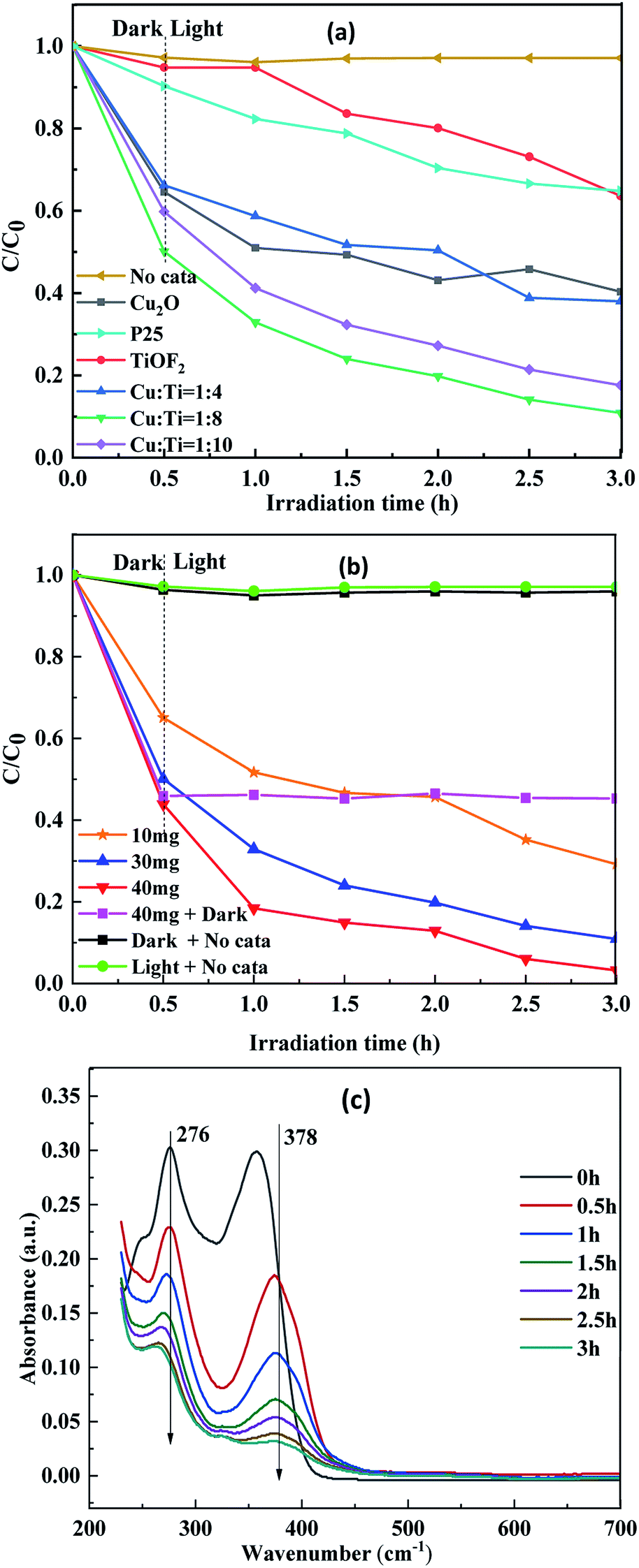
Photocatalytic degradability. Fig. 8 shows the degradation curve of TTCH under different conditions. It can be seen from Fig. 8(a) that Cu2O@TiOF2/TiO2 exhibits good adsorption performance in a dark reaction within 0.5 h and changes with the change of Cu:Ti ratio. This is because random packing promotes the increase of surface area and pores during the deposition of Cu2O on the surface of TiOF2/TiO2. However, when the ratio is too large, Cu2O and TiOF2/TiO2 are excessively deposited, which hinders the contact of TTCH with the catalyst. Therefore, Cu:Ti = 1:8 shows the best adsorption effect, which is consistent with the BET result. The degradation of composite photocatalyst was significantly better than pure TiOF2, pure Cu2O and P25 during the whole degradation process. It can be seen from Fig. 8(b) that the concentration of TTCH does not change significantly when there is no catalyst under simulating solar light. This shows that TTCH exhibits good stability and light from xenon lamps can hardly induce degradation. This may be due to the stable naphthol ring structure of TTCH. Compared to the 40 mg matte curve in Fig. 8(b), the concentration of TTCH is further reduced when both the catalyst and the source are present. It is indicated that the degradation process after TTCH is saturated by adsorption is photocatalytic degradation. When the dosage of Cu:Ti = 1:8 catalyst is 30 mg, the degradation rate of TTCH is 89.14%. However, the addition of 40 mg of catalyst can be as high as 96.83%.
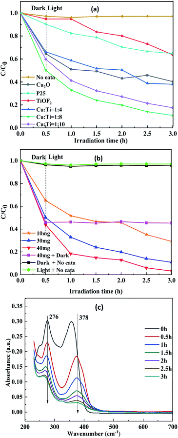 |
| | Fig. 8 (a) Photodegradation of TTCH over different samples under visible light (catalyst dosage is 30 mg); (b) Cu:Ti = 1:8 Cu2O@TiOF2/TiO2 degraded TTCH under different conditions; (c) UV-vis absorption spectrum of Cu:Ti = 1:8 Cu2O@TiOF2/TiO2. | |
It can be seen from Fig. 8(c) that TTCH has two main absorption peaks at 276 nm and 378 nm. The absorption peak at 272 nm may be related to the hydroxyl group and acylamino group produced during the reduction.51,52 The absorption peak at 378 nm is due to the aromatic ring B–D, which may be caused by the cleavage of the phenol ring attached to the aromatic ring.53 After the reaction is carried out for 0.5 h, the absorption peak decreased rapidly. It is indicated that the ring structure was destroyed after the addition of the light source, and the TTCH adsorbed on the catalyst could be further photocatalyzed. According to the study of TTCH degradation process by Peng54 and Wang55 et al., under the attack of active substances such as ·OH, functional groups such as amino group, hydroxyl group and methyl group are first separated from TTCH molecules. Upon further oxidation, the carbon chain is broken, forming an unstable ring opening product. Under the action of free radicals, the carbonyl group is separated from the ring opening. The intermediate is further oxidized to form a short chain carboxylic acid. Finally, the stable ring structure of the TTCH molecule is destroyed to achieve a degradation effect.
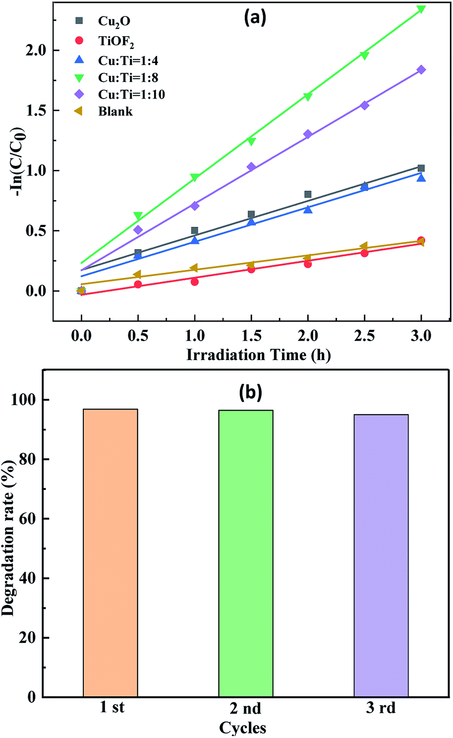
In order to further study and understand the kinetics of photocatalytic degradation of TTCH by Cu:Ti = 1:8 Cu2O@TiOF2/TiO2, the analysis was carried out under optimal conditions. As shown in Fig. 9(a), the composite photocatalyst has a R2 close to 1, consistent with the first order kinetic model. The repeated experimental results of the Cu:Ti = 1:8 composite material are shown in Fig. 9(b). After three repeated use of the catalyst, there is no significant reduction in the degradation of TTCH. This indicates that the catalyst has sufficient stability and repeatability.
 |
| | Fig. 9 (a) The kinetic curves transform of TTCH degradation overdifferent samples; (b) the repetitive degradation diagram of Cu:Ti = 1:8. | |
Mechanism of photocatalytic activity
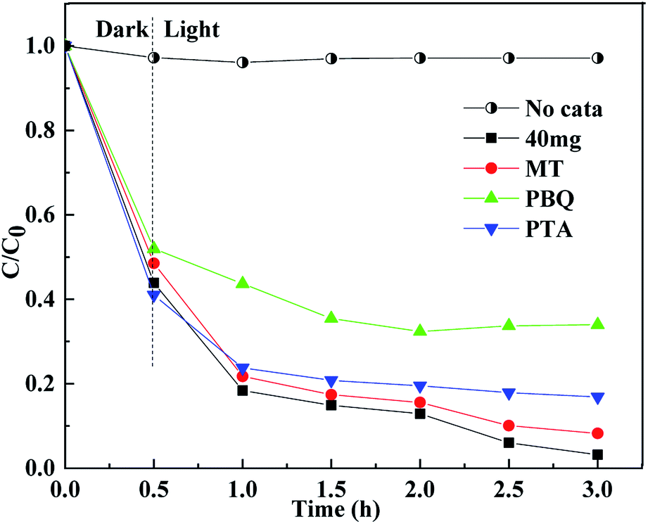
To determine the active substances in the degradation of TTCH, 1,4-benzoquinone (PBQ) was used as a scavenger for superoxideradicals (·O2−).56 1,4-Terephthalic acid (PTA) was used as a scavenger for hydroxyl radicals (·OH).6 Methanol (MT) was used as a scavenger for the hole (h+). The capture experiments were identical to the photocatalytic experiments. As shown in Fig. 10, in the dark reaction stage, the scavenger has a slight effect on the adsorption of the system. It is speculated that the catalyst also has a small amount of adsorption on different scavengers, and the scavenger forms a competitive relationship with TTCH. The combination of different scavengers and catalyst surfaces may also be different, so different catalysts exhibit different adsorption effects in the dark reaction stage. When MT was added to the system, the degradation efficiency of the catalyst did not change much. When PBQ and PTA were added, the degradation rates were reduced by about 40% and 20%, respectively. It can be seen that ·O2− and ·OH determine the degradation activity of the catalyst on TTCH. The O2 molecule is adsorbed on the surface of the catalyst by photoexcitation of electrons, and is reduced to form ·O2−.57
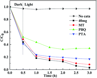 |
| | Fig. 10 Free scavenging experiment of Cu:Ti = 1:8 Cu2O@TiOF2/TiO2 (catalyst dosage is 40 mg, and the concentration of scavenger 3 mmol L−1). | |
Based on above experiments, a possible mechanism for the degradation of TTCH by Cu2O@TiOF2/TiO2 under simulating solar light is proposed, as displayed in Fig. 11. Under simulating solar light (λ > 420 nm) irradiation, the Cu2O is excited and generated photocarriers. Because the CB of Cu2O is a little negative compared to TiO2,58 part of the photogenerated electrons on Cu2O can migrate to the CB of TiO2, and the other part reacts with dissolved oxygen O2 to form ·O2−. Similarly, photogenerated electrons on TiO2 migrate to CB of TiOF2.30,37 On the other hand, holes are accumulated step by step onto the VB of Cu2O, and the low-cost band of Cu2O is advantageous for the transfer of effective holes. These holes can react directly with the TTCH adsorbed on the surface of the catalyst.
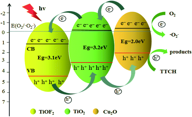 |
| | Fig. 11 Photocatalytic reaction mechanism of degradation of TTCH by Cu2O@TiOF2/TiO2. | |
Conclusions
In summary, an easy hydrothermal route to synthesize Cu2O@TiOF2/TiO2 (Cu:Ti = 1:4, 1:8, 1:10) hybrids has been demonstrated. The prepared Cu2O@TiOF2/TiO2, especially the Cu:Ti = 1:8 nanocomposite, exhibited excellent activity towards the degradation of TTCH under simulating solar light irradiation. A lower electron–hole pairs recombination rate and larger specific surface area, pore diameter are the dominant factor that induces the photocatalytic performance enhancement of Cu2O@TiOF2/TiO2 nanohybrids. The highest efficiency of TTCH removal reached 96.83% in 3 h. The degradation of TTCH is largely dependent on ·O2− and ·OH. Cu2O@TiOF2/TiO2 has good repeatability, which is very important in practical applications. At present, for TTCH, there are few studies that can achieve high efficiency and economy. Therefore, this work opens an avenue for the removal of organic pollutants.
Conflicts of interest
There are no conflicts to declare.
Acknowledgements
This work has been supported by the Shaanxi Province Education Department Science and Technology Research Plan (No. 15JK1460, No. 2019SF-250).
References
- Y. Qi, J. He, F. Xiu, X. Yu, X. Gao, Y. Li, Y. Lu and Z. Song, Microchem. J., 2019, 147, 789–796 CrossRef CAS
 .
. - P. Wang, P. S. Yap and T. T. Lim, Appl. Catal., A, 2011, 399, 252–261 CrossRef CAS .
- F. Xiu, X. Yu, Y. Qi, Y. Li, Y. Lu, Y. Wang, J. He, K. Zhou, Z. Song and X. Gao, Waste Manag., 2019, 100, 191–198 CrossRef CAS PubMed .
- H. Chen, S. Liu, X. Xu, Z. Diao, K. Sun, Q. Hao, S. Liu and G. Ying, J. Hazard. Mater., 2018, 343, 140–148 CrossRef CAS PubMed .
- F. Wu, F. Zhou, Z. Zhu, S. Zhan, Q. He and Q. Hao, Chem. Phys. Lett., 2019, 724, 90–95 CrossRef CAS .
- C. Wang, X. Zhang, H. Qiu, G. Huang and H. Yu, Appl. Catal., B, 2017, 205, 615–623 CrossRef CAS .
- F. Xiu, Y. Li, Y. Qi, X. Yu, J. He, Y. Lu, X. Gao, Y. Deng and Z. Song, Waste Manag., 2019, 84, 355–363 CrossRef CAS PubMed .
- R. D. C. Soltani, G. S. Khorramabadi, A. R. Khataee and S. Jorfi, J. Taiwan Inst. Chem. Eng., 2014, 45, 973–980 CrossRef CAS .
- S. Aydin, B. Ince and O. Ince, Water Res., 2015, 83, 337–344 CrossRef CAS PubMed .
- N. Le-Minh, S. J. Khan, J. E. Drewes and R. M. Stuetz, Water Res., 2010, 44, 4295–4323 CrossRef CAS PubMed .
- F. Zhang, S. Zhu, F. Xie, J. Zhang and Z. Meng, Sep. Purif. Technol., 2013, 113, 1–8 CrossRef CAS .
- W. Zhong, W. Tu, S. Feng and A. Xu, J. Alloys Compd., 2019, 772, 669–674 CrossRef CAS .
- W. Zhong, Z. Lin, S. Feng, D. Wang, S. Shen, Q. Zhang, L. Gu, Z. Wang and B. Fang, Nanoscale, 2019, 11, 4407 RSC .
- G. Guo, P. Li and Z. Yang, Catal. Commun., 2019, 122, 63–67 CrossRef .
- J. Lyu, Z. Zhou, Y. Wang, J. Li, Q. Li, Y. Zhang, X. Ma, J. Guan and X. Wei, J. Hazard. Mater., 2019, 373, 278–284 CrossRef CAS PubMed .
- C. Hou, B. Hu and J. Zhu, Catalysts, 2018, 8, 575 CrossRef .
- Z. Geng, Y. Zhang, X. Yuan, M. Huo, Y. Zhao, Y. Lu and Y. Qiu, J. Alloys Compd., 2015, 644, 734–741 CrossRef CAS .
- W. Zhong, S. Shen, S. Feng, Z. Lin, Z. Wang and B. Fang, CrystEngComm, 2018, 20, 7851 RSC .
- B. Fang, A. Bonakdarpour, K. Reilly, Y. L. Xing, F. Taghipour and D. P. Wilkinsion, ACS Appl. Mater. Interfaces, 2014, 6, 15488–15498 CrossRef CAS PubMed .
- M. Du, B. Qiu, Q. Zhu, M. Xing and J. Zhang, Catal. Today, 2019, 327, 340–346 CrossRef CAS .
- N. Farhadian, R. Akbarzadeh, M. Pirsaheb, T. C. Jen, Y. Fakhri and A. Asadi, Int. J. Biol. Macromol., 2019, 132, 360–373 CrossRef CAS PubMed .
- J. Shao, W. Sheng, M. Wang, S. Li, J. Chen, Y. Zhang and S. Cao, Appl. Catal., B, 2017, 209, 311–319 CrossRef CAS .
- Y. Lu, X. Zhang, Y. Chu, H. Yu, M. Huo, J. Qu, J. C. Crittenden, H. Huo and X. Yuan, Appl. Catal., B, 2018, 224, 239–248 CrossRef CAS .
- W. Zhong, S. Shen, M. He, Z. Wang, Z. Lin, W. Tu and J. Yu, Appl. Catal., B, 2019, 258, 117967 CrossRef CAS .
- P. Dong, E. Cui, G. Hou, R. Guan and Q. Zhang, Mater. Lett., 2015, 143, 20–23 CrossRef CAS .
- J. Wang, F. Gao, Z. Bian, M. K. H. Leung and H. Li, Nanoscale, 2014, 6, 897–902 RSC .
- X. Zhao, G. Wei, J. Liu, Z. Wang, C. An and J. Zhang, Mater. Res. Bull., 2016, 80, 337–343 CrossRef CAS .
- K. Lva, J. Yua, L. Cui, S. Chen and M. Li, J. Alloys Compd., 2011, 509, 4557–4562 CrossRef .
- C. Hou and W. Liu, R. Soc. Open Sci., 2018, 5, 172005 CrossRef PubMed .
- Z. Liu, X. Liu, Q. Lu, Q. Wang and Z. Ma, J. Taiwan Inst. Chem. Eng., 2019, 96, 214–222 CrossRef CAS .
- Y. Tan, X. Xue, Q. Peng, H. Zhao, T. Wang and Y. Li, Nano Lett., 2007, 7, 3723–3728 CrossRef CAS .
- W. Zou, L. Zhang, L. Liu, X. Wang, J. Sun and S. Wu, Appl. Catal., B, 2016, 181, 495–503 CrossRef CAS .
- Y. Yue, P. Zhang, W. Wang, Y. Cai, F. Tan and X. Wang, J. Hazard. Mater., 2020, 384, 121302 CrossRef CAS PubMed .
- Y. Pu, Y. Luo, X. Wei, J. Sun, L. Li, W. Zou and L. Dong, Appl. Catal., B, 2019, 254, 580–586 CrossRef CAS .
- X. Wen, M. Long and A. D. Tang, J. Electroanal. Chem., 2017, 785, 33–39 CrossRef CAS .
- C. Hou, W. Liu and J. Zhu, Catalysts, 2017, 7, 243 CrossRef .
- Z. Huang, Z. Wang and K. Lv, ACS Appl. Mater. Interfaces, 2013, 5, 8663–8669 CrossRef CAS PubMed .
- S. Zhao, J. Chen, Y. Liu, Y. Jiang, C. Jiang, Z. Yin, Y. Xiao and S. Cao, Chem. Eng. J., 2019, 367, 249–259 CrossRef CAS .
- D. C. T. Nguyen, K. Y. Cho and W. C. Oh, RSC Adv., 2017, 7, 29284–29294 RSC .
- L. Rekeb, L. Hamadou, A. Kadri, N. Benbrahim and E. Chainet, Int. J. Hydrogen Energy, 2019, 44, 10541–10553 CrossRef CAS .
- C. Hou, J. Zhu and Q. Song, Catalysts, 2018, 8, 70 CrossRef .
- J. Zhao, D. C. T. Nguyen, Y. Areerob and W. C. Oh, Solid State Sci., 2019, 91, 77–88 CrossRef CAS .
- M. He, Z. Wang, X. Yan, L. Tian, G. Liu and X. Chen, J. Power Sources, 2016, 306, 309–316 CrossRef CAS .
- H. Zhang, D. Zhang, L. Guo, R. Zhang, P. Yin and R. Wang, J. Nanosci. Nanotechnol., 2008, 8, 6332–6337 CAS .
- M. Hu, Y. Cao, Z. Li, S. Yang and Z. Xing, Appl. Surf. Sci., 2017, 426, 734–744 CrossRef CAS .
- Z. Gao, J. Liu, F. Xu, D. Wu, Z. Wu and K. Jiang, Solid State Sci., 2012, 14, 276–280 CrossRef CAS .
- P. Wang, C. Qi, L. Hao, P. Wen and X. Xu, J. Mater. Sci. Technol., 2019, 35, 285–291 CrossRef .
- X. Zhao, G. Wei, J. Liu, Z. Wang, C. An and J. Zhang, Mater. Res. Bull., 2016, 80, 337–343 CrossRef CAS .
- Y. Bai, Z. Li, B. Cheng, M. Zhang and K. Su, RSC Adv., 2017, 7, 21758–21767 RSC .
- Q. Zhu, Y. Zhang, F. Lv, P. Chu, Z. Ye and F. Zhou, J. Hazard. Mater., 2012, 217, 11–18 CrossRef PubMed .
- G. Safari, M. Hoseini, M. Seyedsalehi, H. Kamani, J. Jaafari and A. Mahvi, Int. J. Environ. Sci. Technol., 2015, 12, 603–616 CrossRef CAS .
- X. Zhu, Y. Wang, R. Sun and D. Zhou, Chemosphere, 2013, 92, 925–932 CrossRef CAS PubMed .
- M. Khodadadi, M. H. Ehrampoush, M. T. Ghaneian, A. Allahresani and A. H. Mahvi, J. Mol. Liq., 2018, 255, 224–232 CrossRef CAS .
- Y. Peng, L. Kong, H. Lei, D. Chen and G. Yuvaraja, J. Taiwan Inst. Chem. Eng., 2018, 1–8 Search PubMed .
- Q. Wang, P. Li, Z. Zhang, C. Jiang, K. Zoujiao and J. Liu, J. Photochem. Photobiol., A, 2019, 378, 114–124 CrossRef CAS .
- D. Wang, F. Jia, H. Wang, F. Chen, Y. Fang, W. Dong, G. Zeng, X. Li, Q. Yang and X. Yuan, J. Colloid Interface Sci., 2018, 519, 273–284 CrossRef CAS PubMed .
- F. Wu, F. Zhou, Z. Zhu, S. Zhan and Q. He, Chem. Phys. Lett., 2019, 724, 90–95 CrossRef CAS .
- J. Wang, G. Ji, Y. Liu, M. Gondal and X. Chang, Catal. Commun., 2014, 46, 17–21 CrossRef CAS .
|
| This journal is © The Royal Society of Chemistry 2019 |
Click here to see how this site uses Cookies. View our privacy policy here. 
 Open Access Article
 This Open Access Article is licensed under a Creative Commons Attribution-Non Commercial 3.0 Unported Licence
 *,
Jianqiong Xie
*,
Jianqiong Xie