 Open Access Article
Hollow core–shell structured TS-1@S-1 as an efficient catalyst for alkene epoxidation†
J. Wang,
Z. Chen,
Y. Yu,
Z. Tang,
K. Shen,
R. Wang,
H. Liu,
X. Huang and
Y. Liu *
*
Shanghai Key Laboratory of Green Chemistry and Chemical Processes, School of Chemistry and Molecular Engineering, East China Normal University, North Zhongshan Rd 3663, Shanghai 200062, P. R. China. E-mail: ymliu@chem.ecnu.edu.cn; Fax: +86-21-6223-2058; Tel: +86-21-6223-2058
First published on 20th November 2019
Abstract
Hollow core–shell structured TS-1@S-1 zeolite (HCS-TS) was prepared successfully for the first time, which exhibited excellent activity in the epoxidation of alkenes. Combining TEM, UV-vis, UV-Raman, pyridine-IR, solid-state MAS NMR, XPS and so on characterization, the improvement in the catalytic performance of hollow core–shell structured TS-1@S-1 zeolite was credited to the newly formed superior active sites: defective Ti(OSi)3(OH) species in HCS-TS and six-coordinated titanium active species in uncalcined HCS-TS (HCS-TSP). Interestingly, these two different titanium active species in the samples could be constructed through calcination or not in the same synthesis process. A possible formation mechanism was investigated in detail; it indicated that the hollowing treatment of TS-1 in the first step was conducive to the construction of the new superior active sites in the samples, and there was a synergistic effect on the formation of these active sites between TPAOH and TEOS in the second step of the synthesis process. This strategy is feasible to enhance the catalytic performance of TS-1, and is suitable for the synthesis of TS-1 on an industrial scale.
1. Introduction
The discovery of TS-1 was a milestone in zeolite and heterogeneous catalysis research fields.1 Meanwhile, green synthesis of oxygenated products with high selectivity has been achieved based on the TS-1/H2O2 catalytic system.2–4 The further improvement of the catalytic performance of TS-1 has obtained great interest from both industrial and academic communities. Great efforts on the study of diffusion constraints,5–9 Ti active sites,10,11 reactive intermediates,12 and additives13,14 have been made during the past four decades.It was commonly accepted that tetrahedral coordination isolated Ti species in titanosilicates was the active sites, and it could activate H2O2 to form the titanium hydroperoxo intermediates, which acted as the important role in the transfer of “O”.15,16 There were two types of Lewis acid centers as Ti(OSi)4 and Ti(OSi)3OH species in titanosilicates respectively.17 Through DFT calculation, Wells et al.10 found that Ti(OSi)3OH had smaller steric hindrance effect, which made the energy barrier of activating H2O2 in TS-1 much lower than that of Ti(OSi)4. Wang et al.18–21 also proposed that the Ti(OSi)3OH species were beneficial for the formation of the active intermediate Ti–OOH, which was owing to their stronger Lewis acidity. Selective dissolution of Si species around Ti(OSi)4 sites of TS-1 could directionally construct active Ti(OSi)3OH species.22 Interestingly, the Ti species with other coordination environments, such as Ti(V) species and the Ti(VI) species surrounded with nearby Si vacancies, could also take responsible for a superior catalytic activity in various Ti-catalyzed reactions.10,23,24 Wu et al. successfully synthesized TS-1+ with stable six-coordination Ti species (“TiO6”), it showed a superior activity in the oxidation of propylene to propylene oxide with the TON value increasing about 2–3 times than TS-1.25 And the six-coordinated Ti species (Ti(OSi)2(OH)2(H2O)(PI)) in Re-Ti-MWW-PI zeolites has exhibited an unprecedented high catalytic activity and recyclability in alkene epoxidation as well.15 These studies all provided evidences for the diversity of Ti active species in titanosilicates and confirmed their advantages in the enhancement of their catalytic performance.
In this contribution, TS-1@S-1 (HCS-TS) zeolite with hollow core–shell structure was synthesized successfully for the first time, which showed an improved catalytic activity in the epoxidation of alkenes. Systematic results indicated that the better catalytic performance was mainly due to the formation of defective Ti(OSi)3(OH) active species in HCS-TS and six-coordinated Ti active species in uncalcined HCS-TS (HCS-TSP). Interestingly, these two different Ti species could be obtained at different stages during the synthesis process. This information could give us ideas on synthesizing a series of titanosilicates with highly catalytic performance.
2. Experimental
2.1 Catalysts preparation
TS-1 was hydrothermally synthesized following the procedure reported in patent literature developed by ENI group,1 using tetraethyl orthosilicate (TEOS) and tetrabutyl orthotitanate (TBOT) as silicon and titanium source respectively, and tetrapropylammonium hydroxide (25 wt%) as structure-directing agent (SDA). The synthetic gel with the molar compositions of 1.0 SiO2![[thin space (1/6-em)]](https://www.rsc.org/images/entities/char_2009.gif) :
:![[thin space (1/6-em)]](https://www.rsc.org/images/entities/char_2009.gif) x TiO2
x TiO2![[thin space (1/6-em)]](https://www.rsc.org/images/entities/char_2009.gif) :
:![[thin space (1/6-em)]](https://www.rsc.org/images/entities/char_2009.gif) 0.18 TPAOH
0.18 TPAOH![[thin space (1/6-em)]](https://www.rsc.org/images/entities/char_2009.gif) :
:![[thin space (1/6-em)]](https://www.rsc.org/images/entities/char_2009.gif) 18 H2O, x = 0.010–0.033, was crystallized in a 100 mL Teflon-lined autoclave under 443 K for 48 h under static conditions. The product was recovered by filtration using deionized water for 2–3 times, drying in oven at 353 K for 12 h, and calcinations in muffle furnace at 823 K for 6 h, denoted as TS-1-x (x stands for Si/Ti). If not special description, the Si/Ti in TS-1 was 90.
18 H2O, x = 0.010–0.033, was crystallized in a 100 mL Teflon-lined autoclave under 443 K for 48 h under static conditions. The product was recovered by filtration using deionized water for 2–3 times, drying in oven at 353 K for 12 h, and calcinations in muffle furnace at 823 K for 6 h, denoted as TS-1-x (x stands for Si/Ti). If not special description, the Si/Ti in TS-1 was 90.
HCS-TS was prepared by two steps. In the first step, H-TS-1 was obtained by post-treatment of the TS-1 in alkaline system following the procedure reported in literature.26 Typically, 4 g TS-1 was suspended in 14.642 g TPAOH (25 wt%) solution, the molar compositions of final mixture was 1.0 Si![[thin space (1/6-em)]](https://www.rsc.org/images/entities/char_2009.gif) :
:![[thin space (1/6-em)]](https://www.rsc.org/images/entities/char_2009.gif) 0.27 TPAOH
0.27 TPAOH![[thin space (1/6-em)]](https://www.rsc.org/images/entities/char_2009.gif) :
:![[thin space (1/6-em)]](https://www.rsc.org/images/entities/char_2009.gif) 9.1 H2O, after stirring for 1 h, the mixture was crystallized in a 100 mL Teflon-lined autoclave under 443 K for 72 h under static conditions. The product was recovered by filtration, drying, and calcinations as mentioned above, denoted as H-TS-1-x (x stands for Si/Ti). If not special description, the Si/Ti in H-TS-1 was 90. In the second step, HCS-TS was hydrothermally synthesized as similar procedure for S-1, the molar compositions of the synthetic mixture was 1.0 SiO2
9.1 H2O, after stirring for 1 h, the mixture was crystallized in a 100 mL Teflon-lined autoclave under 443 K for 72 h under static conditions. The product was recovered by filtration, drying, and calcinations as mentioned above, denoted as H-TS-1-x (x stands for Si/Ti). If not special description, the Si/Ti in H-TS-1 was 90. In the second step, HCS-TS was hydrothermally synthesized as similar procedure for S-1, the molar compositions of the synthetic mixture was 1.0 SiO2![[thin space (1/6-em)]](https://www.rsc.org/images/entities/char_2009.gif) :
:![[thin space (1/6-em)]](https://www.rsc.org/images/entities/char_2009.gif) 0.18 TPAOH
0.18 TPAOH![[thin space (1/6-em)]](https://www.rsc.org/images/entities/char_2009.gif) :
:![[thin space (1/6-em)]](https://www.rsc.org/images/entities/char_2009.gif) 18 H2O. SiO2 came from H-TS-1 and TEOS, if not special description, TEOS
18 H2O. SiO2 came from H-TS-1 and TEOS, if not special description, TEOS![[thin space (1/6-em)]](https://www.rsc.org/images/entities/char_2009.gif) :
:![[thin space (1/6-em)]](https://www.rsc.org/images/entities/char_2009.gif) H-TS-1 = 1
H-TS-1 = 1![[thin space (1/6-em)]](https://www.rsc.org/images/entities/char_2009.gif) :
:![[thin space (1/6-em)]](https://www.rsc.org/images/entities/char_2009.gif) 9 (based on SiO2, molar ratio). Typically, TEOS was hydrolyzed with TPAOH solution, then H-TS-1 well dispersed in water was added. The mixture was crystallized in a 100 mL Teflon-lined autoclave under 443 K for 72 h under static conditions. After filtration by deionized water for 2–3 times, the product marked as HCS-TSP was obtained by drying in oven at 353 K for 12 h under the condition of flowing air. HCS-TSP was further calcined in muffle furnace at 823 K for 6 h, the product HCS-TS was formed.
9 (based on SiO2, molar ratio). Typically, TEOS was hydrolyzed with TPAOH solution, then H-TS-1 well dispersed in water was added. The mixture was crystallized in a 100 mL Teflon-lined autoclave under 443 K for 72 h under static conditions. After filtration by deionized water for 2–3 times, the product marked as HCS-TSP was obtained by drying in oven at 353 K for 12 h under the condition of flowing air. HCS-TSP was further calcined in muffle furnace at 823 K for 6 h, the product HCS-TS was formed.
2.2 Catalysts characterization
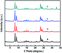
The X-ray diffraction (XRD) patterns were measured on a Rigaku Ultima IV diffractometer (35 kV and 25 mA) using Cu Kα radiation (λ = 1.5405 Å) in the 2θ angle range from 2° to 35°. Transmission electron microscopy (TEM) was taken on a JSM-2010F microscope. N2 adsorption and desorption (BET) measurements were carried out at 77 K on BELSORP-MAX instrument after outgassing the samples under vacuum at 373 K for 3 h. Inductively coupled plasma (ICP) atomic emission spectroscopy was performed on a Thermo IRIS Intrepid II XSP atomic emission spectrometer after dissolving the samples in HF solution. X-ray photoelectron spectra (XPS) were acquired with a Thermo Scientific ESCALAB250xi instrument using X-ray monochromatisation and operating at a constant power of 200 W. The UV-Visible diffuse reflectance spectra (UV-Vis) were recorded on a Shimadzu UV-2400PC spectrophotometer using BaSO4 plate as a reference. The infrared (IR) spectra were collected on Nicolet Nexus 670 FT-IR spectrometer at a spectral resolution of 2 cm−1. 29Si and 13C solid-state MAS NMR spectra were recorded on a VARIAN VNMRS-400WB spectrometer under one pulse condition. FT-IR of adsorbed pyridine (Py-IR) was recorded as follows: a self-supported wafer (25 mg and radius of 6.5 mm) was set in an in situ cell with CaF2 windows connected with a vacuum system. After the sample was evacuated at 723 K for 1 h, the pyridine adsorption was carried out by exposing the wafer to pyridine vapor (1.3 kPa) at 298 K for 15 min. The physisorbed and chemisorbed pyridine was then removed by evacuation at different temperatures (323, 373, 423, 473, and 523 K). The spectra were recorded on a Nicolet iS50 FT-IR spectrometer. UV Raman spectra were recorded on UV-RAMAN100 Raman spectrometer made by Beijing ZOLIX INSTRUMENTS CO. LTD. A 244 nm line of a Lexel laser of a He–Gd laser were used as the excitation sources. The obtained spectra were analyzed by a curve-fitting program XPSPEAK41. Thermogravimetric analysis (TGA) was carried out with TGA/SDTA851e thermogravimetric analyzer produced by Mettler-Toledo Company in air atmosphere. The test range was from 298 K to 1073 K, and the heating rate was 10 K min−1.2.3 Catalytic reaction
The epoxidations of different alkenes were carried out at 333 K for 2 h in a 50 mL round-bottomed flask equipped with a reflux condenser. In a typical reaction, 50 mg of catalyst, 10 mL of CH3OH, 10 mmol of alkene, and 10 mmol of H2O2 (30 wt% aqueous solution) under vigorous stirring. The product was analyzed on an Agilent GC-7890A gas chromatograph equipped with a DB-WAX capillary column (30 m × 320 μm × 0.25 μm) and an FID detector using 0.5 g of cyclohexanone as an internal standard. The residual free H2O2 was determined by the titration method with 0.05 M Ce(SO4)2 solution.3. Results and discussion
3.1 Structural analysis and characterization
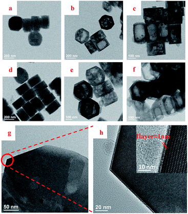 | ||
Fig. 2 TEM images of TS-1 (a and d), H-TS-1 (b and e), HCS-TS (TEOS![[thin space (1/6-em)]](https://www.rsc.org/images/entities/char_2009.gif) : :![[thin space (1/6-em)]](https://www.rsc.org/images/entities/char_2009.gif) H-TS-1-80 = 1 H-TS-1-80 = 1![[thin space (1/6-em)]](https://www.rsc.org/images/entities/char_2009.gif) : :![[thin space (1/6-em)]](https://www.rsc.org/images/entities/char_2009.gif) 9) (c and f) and HCS-TS (TEOS 9) (c and f) and HCS-TS (TEOS![[thin space (1/6-em)]](https://www.rsc.org/images/entities/char_2009.gif) : :![[thin space (1/6-em)]](https://www.rsc.org/images/entities/char_2009.gif) H-TS-1-80 = 0.25 H-TS-1-80 = 0.25![[thin space (1/6-em)]](https://www.rsc.org/images/entities/char_2009.gif) : :![[thin space (1/6-em)]](https://www.rsc.org/images/entities/char_2009.gif) 9.75) (g and h). 9.75) (g and h). | ||
TEM images further confirmed the formation of core–shell structure of HCS-TS. The different crystalline planes of the core and shell both with MFI structure were observable in Fig. 2g and h. Specifically, the lattice spacing of shell was about 1 nm in thickness and the crystalline order shown in Fig. 2h was consistent with the S-1,28,29 which illustrated that the shell was S-1 rather than amorphous substance (Fig. 2h). With the increase of TEOS content in the second step of synthesis, the thickness of shell increased gradually (Fig. S1a–d, ESI†), which was similar to the phenomenon in most core–shell molecular sieves.30,31
The N2 adsorption–desorption isotherms were shown in Fig. S2, ESI† and the corresponding physicochemical properties were summarized in Table S1, ESI.† The adsorption–desorption isotherms of TS-1 was attributed to type I, indicating that there was no significant mesoporosity. While H-TS-1 had a type IV with H4 hysteresis loop, along with the mesoporous volume increased.32 HTS-CS showed the characters of both H4 hysteresis loop of H-TS-1 and type I adsorption–desorption curve of S-1,33 which also exemplified that S-1 grew on the H-TS-1. In the case of HCS-TSP, a part of micropores and mesopores were covered by organics, leading to the decrease of both microporous volume and mesoporous volume (Table S1, ESI†). However, the results of epoxidation reaction (Table 1) inferred that the performance of the catalyst was not affected, in line with the results of Au/TS-1-B34,35 and Re-Ti-MWW-PI.15
| No. | Catalyst | Si/Tib | I960/I550 | Alkene epoxidation | |||||
|---|---|---|---|---|---|---|---|---|---|
| 1-Hexene | Cyclopentene | Cyclohexene | |||||||
| Conv./% | TON | Conv./% | TON | Conv./% | TON | ||||
| a Reaction conditions: cat. 50 mg, alkene 10 mmol, H2O2 10 mmol, CH3OH 10 mL, temp. 333 K, time 2 h.b Detected by ICP. | |||||||||
| 1 | TS-1 | 90 | 0.251 | 16.5 | 180 | 23.8 | 260 | 0.5 | — |
| 2 | H-TS-1 | 90 | 0.209 | 16.4 | 179 | 20.3 | 222 | 0.5 | — |
| 3 | HCS-TS | 98 | 0.149 | 21.5 | 256 | 23.8 | 283 | 0.4 | — |
| 4 | HCS-TSP | 98 | 0.049 | 25.1 | 299 | 48.1 | 572 | 0.9 | — |
The elemental analysis of TS-1 samples was shown in Table S2, ESI† by ICP-AES for bulk and XPS for the surface. ICP results showed that the Si/Ti ratio in the bulk of H-TS-1 did not change in contrasted with TS-1. However, that of HCS-TS increased due to the outer S-1 coating. Meanwhile, the Si/Ti ratios on the surface of HCS-TS and HCS-TSP were larger than TS-1 and H-TS-1, which also confirmed the Si-rich situation in hollow TS-1@S-1 zeolite.
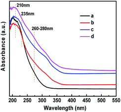
The existence of Ti(OSi)3OH active sites in HCS-TS was further certified. The IR spectra in the hydroxyl region (Fig. 4c) demonstrated that HCS-TS had more Ti–OH groups, with an obvious absorption band at 3676 cm−1, whereas it was difficult to be detected in TS-1 and H-TS-1,22 consistent with the peak of 235 nm formed in UV-vis spectra. Furthermore, the absorption band at 3500 cm−1 was attributed to hydrogen-bonded silanol nests.41,42 Compared with TS-1, the intensity of the band at 3500 cm−1 decreased obviously for H-TS-1 and HCS-TS, indicating that H-TS-1 and HCS-TS were more hydrophobic than parent TS-1 (Fig. 4),43 which was in line with the decrease of Q3 (Si(OSi)3OH) of H-TS-1 and HCS-TS in 29Si NMR MAS (Fig. S4 and Table S3, ESI†).44
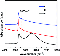 | ||
| Fig. 4 The FT-IR spectra in the hydroxyl stretching evacuated at 723 K in the range of 1500–4000 cm−1. (a) TS-1; (b) H-TS-1; (c) HCS-TS. | ||
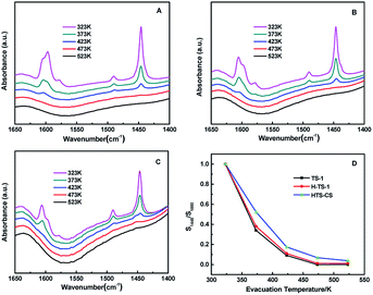
It was also reported that the Lewis acid strength of Ti(OSi)3OH sites was stronger than Ti(OSi)4 sites based on DFT calculation.45–47 The strength of Lewis acidity of different samples were investigated by FT-IR of adsorbed pyridine. The infrared absorption at 1445 cm−1 was ascribed to Lewis acid sites bonded with the pyridine species.48 Fig. 5A–C affirmed that the three samples had mainly Lewis acid sites, while the Brønsted acid sites were negligible, as evidenced by the extremely weak bands at 1540 cm−1. The strength of Lewis acidity was contrasted by the further semi-quantitative analysis, suggesting that HCS-TS did have a stronger Lewis acidity, while that of TS-1 and H-TS-1 were almost identical (Fig. 5D).22,25,45,49 The above results implied the existence of open tetra-coordinated titanium (Ti(OSi)3OH) species in HCS-TS.22
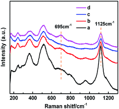
UV resonance Raman spectroscopy was applied to further identify the newly formed “TiO6” species in HCS-TSP, which triggered the UV-Vis absorption band at 260 nm (Fig. 3d). In all samples, three main bands were detected at 490, 530 and 1125 cm−1 (Fig. 6), ascribed to the symmetric stretching and asymmetric stretching vibrations of framework Ti–O–Si species due to the resonance Raman effect.50,51 Meanwhile, it was worth noting that a new band at 695 cm−1 was observed in HCS-TSP, assigned to“TiO6” species,24,25 while it was absent in the Raman spectra of the other three samples (Fig. 6).
To have a deep understanding of the coordination state of “TiO6” species, a comprehensive analysis of HCS-TSP was carried out. The thermogravimetric analysis (TGA) of HCS-TSP (Fig. S5A, ESI†) showed that there were a remarkable weight-loss at 200 °C and a ∼2.6% weight-loss above 350 °C, which demonstrated the existence of water and TPAOH.52 Correspondingly, 13C MAS NMR spectra of HCS-TSP (Fig. S5B, ESI†) revealed that three main signal peaks at 10.3 ppm, 15.8 ppm and 63.5 ppm, which were mainly attributed to the carbon species of TPA+ in the channel.53 Besides, the peaks associated with TPAOH in HCS-TSP could also be observed by FT-IR spectra (Fig. S3B, ESI†). All of these indicated that TPAOH-related substances did exist in uncalcined HCS-TSP.
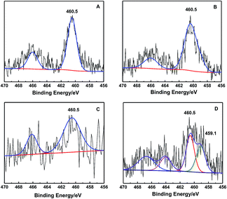
Moreover, XPS is a surface-sensitive technique, it can be used to analyze elements and their oxidation states. It was employed to confirm the existence of the “TiO6” species (Fig. 7). In hollow core–shell samples, Ti species could also be detected owing to the S-1 shell was thin. Additionally, the binding energy (BE) is closely related to the estimated charges on the central atoms.15,54 Fig. 7B showed that the post-treatment of TS-1 did not change the BE of framework tetrahedral coordination “TiO4” species. However, the HCS-TSP had a shoulder peak at 459.1 eV besides the BE of Ti 2p3/2 at 460.5 eV for TS-1 (Fig. 7A and D), making it clear that the charge distribution of the Ti ions in HCS-TSP became more negative. Further calcination caused the BE to change back to 460.5 eV for HCS-TS (Fig. 7C), and the peak at 459.1 eV in HCS-TSP disappeared due to the decomposition of the organics, which provided the possibility of TPAOH ligands and water coordinating directly to the Ti active sites, shown as Ti(OSi)3(OH)(H2O)(TPA+).25,50 It was similar to the Re-Ti-MWW-PI with six-coordinated Ti species,15 but the typical BE of Ti 2p3/2 for HCS-TSP was slightly different from Re-Ti-MWW-PI, which might be caused by the different organic compounds.
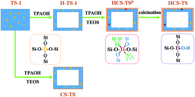
Based on the above characterizations, it was concluded that the microporous TS-1 was treated by TPAOH to obtain H-TS-1 with mesopores. After further crystallization treatment, the surface of the H-TS-1 core was covered with S-1 shell to synthesize HCS-TSP, and HCS-TS was obtained by further calcination. Interestingly, different from the tetrahedral coordination “TiO4” species in TS-1 and H-TS-1, defective Ti(OSi)3(OH) species in HCS-TS and six-coordinated titanium active species coordinated by TPA+ in HCS-TSP were created successfully in the same process by calcination or not.
3.2 Catalytic performance of samples
The catalytic performances of all samples were investigated according to the epoxidation of alkenes (Tables 1 and S4, ESI† for the specific experimental results). The conversion of 1-hexene over H-TS-1 was similar to that of TS-1 (Table 1), which implied that the mesopores in H-TS-1 had no obvious effect on the improvement of catalytic performance, this was the same as TS-1-TPAOH.25 However, some other studies found that the formation of mesopores or nanocubes was favorable for the elimination of diffusion restriction, thus improving the catalytic activity.55,56 The most probable reason was that the positive effects of H-TS-1 caused by the increase of hydrophobicity and the weakening of diffusion restriction, which were shielded by the side effect caused by the formation of anatase. The hollow core–shell TS-1@S-1 catalysts exhibited excellent activities, owing to the formation of different Ti active sites. The TON of HCS-TS was 256, which was 42% higher than that of TS-1 (TON = 180). Meanwhile, the TON of HCS-TSP increased around 66%. Remarkably, HCS-TS and HCS-TSP with the same core–shell structure had different catalytic properties, which illustrated that different Ti active sites played major roles in the improvement of catalytic performance.In the epoxidation of cyclopentene (Tables 1 and S4, ESI†), the catalytic performance of HCS-TS (TON = 283) and HCS-TSP (TON = 572) also improved significantly. However, the catalytic performance of samples with mesoporous structure only got a slight increase in the epoxidation of cyclohexene. It could speculate that no more Ti species were formed on the surface of H-TS-1, which conformed to the results of XPS (Fig. 7B). On the other hand, it was difficult for macromolecule to pass through the micropores of the S-1 shell.
In addition, TS-1 with various Ti contents were applied to synthesize HCS-TS molecular sieves in the same way. The conversion of 1-hexene with HCS-TS and HCS-TSP was higher than with TS-1 under various parent Ti contents (Fig. S6A, ESI†), and HCS-TSP had the best catalytic performance. Meanwhile, the curve of I960/I550 changing with Ti contents (Fig. S6B, ESI†) showed that the corresponding framework tetra-coordinated Ti content of HCS-TS and HCS-TSP was less than that of TS-1, which also proved that the different Ti-coordinated species proposed above were transformed from the framework tetra-coordinated species, and the various changes of I960/I550 were related to different states of titanium in the skeleton.40
The stability of HCS-TS and HCS-TSP was checked in 1-hexene epoxidation (Fig. S7, ESI†). For HCS-TS and HCS-TSP, the conversion of 1-hexene both decreased gradually with the increase of recycling times, probably owing to the organic substance blocking the pores. However, after four cycles, the reactivity of the two zeolites was still higher than that of parent TS-1. For HCS-TSP, the decrease of 1-hexene conversion might also be due to the leaching of TPAOH molecules.15 After HCS-TS and HCS-TSP had been reused four times, they were regenerated by calcination at 823 K. The regenerated catalysts showed almost restored activity in the fifth run. Meanwhile, as HCS-TSP was transformed into HCS-TS by calcination, the conversion of 1-hexene of the two zeolites was equivalent after the fifth run. The results confirmed that the hollow core–shell structured TS-1@S-1 zeolite was advantageous to selective oxidation.
3.3 Possible formation mechanism of HCS-TS
| No. | Samples | Conv. (1-hexene)/% | Conv. (H2O2)/% | Eff. (H2O2)/% | Sel. (Epo.)/% | TON |
|---|---|---|---|---|---|---|
| a Reaction conditions: cat. 50 mg, 1-hexene 10 mmol, H2O2 10 mmol, CH3OH 10 mL, temp. 333 K, time 2 h. | ||||||
| 1 | TS-1 | 16.5 | 19.3 | 85.2 | 100.0 | 180 |
| 2 | CS-TS | 16.5 | 20.8 | 76.5 | 96.1 | 181 |
| 4 | HCS-TS | 21.5 | 25.3 | 84.9 | 100.0 | 256 |
| 5 | HCS-TSP | 25.1 | 27.7 | 86.1 | 95.0 | 299 |
| No. | Samples | Conv. (1-hexene)/% | Conv. (H2O2)/% | Eff. (H2O2)/% | Sel. (Epo.)/% | TON |
|---|---|---|---|---|---|---|
| a Reaction conditions: cat. 50 mg, 1-hexene 10 mmol, H2O2 10 mmol, CH3OH 10 mL, temp. 333 K, time 2 h. | ||||||
| 1 | TS-1 | 16.5 | 19.3 | 85.2 | 100.0 | 180 |
| 2 | H-TS-1 | 16.4 | 19.5 | 83.7 | 99.4 | 179 |
| 3 | H-TS-1-TEOS | 13.0 | 15.3 | 82.7 | 97.5 | 186 |
| 4 | H-TS-1-TPAOH | 18.4 | 20.3 | 88.7 | 97.8 | 178 |
| 5 | HCS-TS | 21.5 | 25.3 | 84.9 | 100.0 | 256 |
Based on the systematic characterization of the hollow core–shell structured TS-1@S-1 zeolite, a possible formation mechanism could be figured out (Fig. 8). In the macro-viewpoint, smooth-surfaced TS-1 was treated with TPAOH in hydrothermal condition, with the inner part of TS-1 forming mesoporous and the outer surface further crystallizing to be hexagon (H-TS-1). After the treatment of TPAOH and TEOS in the second step of crystallization, a certain thickness of the shell was formed (HCS-TSP), and the shape did not change obviously in the further calcination process (HCS-TS). Additionally, TS-1 was directly coated with S-1 (CS-TS), and the CS-TS zeolite had a very thin shell, indicating that the main function of TPAOH was to create mesopores in the same process with HCS-TS. In the micro-perspective, compared with TS-1 zeolite with a set number of silanol groups (Si–OH) on its surface,41,42 less Si–OH were formed on the surface of H-TS-1 owing to recrystallization. Meanwhile, it had still tetrahedrally coordinated titanium (“TiO4”) species. In subsequent synthesis, due to the synergetic effect of TEOS and TPAOH, some Si species adjacent to the skeleton Ti sites were selectively removed to coordinate the Ti species in HCS-TSP with TPA+, resulting in the generation of “TiO6” units.15 After calcination, the organic amines and water were removed to form a defective “open” site, Ti(OSi)3(OH). On the other hand, the CS-TS still hold tetrahedrally coordinated titanium species as same as H-TS-1.
4. Conclusions
In summary, hollow core–shell structured TS-1@S-1 (HCS-TS) were synthesized via post-treatment of TS-1 and coating S-1 on the outer layer of H-TS-1. The novel HCS-TS showed superior catalytic activities in alkene epoxidation than parent TS-1. During the synthesis process, post-treatment of TS-1 was a key step, it was not only conducive to the formation of mesopores in hollow core–shell molecular sieves, but also instrumental in the construction of different Ti coordination states: six-coordinated titanium active sites in HCS-TSP, and defective Ti(OSi)3(OH) sites in HCS-TS. Additionally, there was a synergistic effect between TPAOH and TEOS on the improvement of catalytic performance. It was the first time to synthesize hollow core–shell structure titanosilicates with two different coordination state of titanium species in the same process by calcination or not, which offered the potentials for the further applications in oxidation reactions and prolonging the life of catalysts.Conflicts of interest
There are no conflicts to declare.Acknowledgements
The authors gratefully acknowledge the financial support from the National Natural Science Foundation of China (21673076).Notes and references
- M. Taramasso, G. Perego and B. Notari, US Pat., 4410501, 1983.
- H. Ichihashi and H. Sato, Appl. Catal., A, 2001, 221, 359 CrossRef CAS.
- V. Russo, R. Tesser, E. Santacesaria and M. Di Serio, Ind. Eng. Chem. Res., 2013, 52, 1168 CrossRef CAS.
- Y. Wei, G. Li, Q. Lü, C. Cheng and H. Guo, Chin. J. Catal., 2018, 39, 964 CrossRef CAS.
- K. Na, C. Jo, J. Kim, W.-S. Ahn and R. Ryoo, ACS Catal., 2011, 1, 901 CrossRef CAS.
- W. Fan, P. Wu, S. Namba and T. Tatsumi, Angew. Chem., Int. Ed. Engl., 2004, 43, 236 CrossRef CAS PubMed.
- H. Xin, J. Zhao, S. Xu, J. Li, W. Zhang, X. Guo, E. J. M. Hensen, Q. Yang and C. Li, J. Phys. Chem. C, 2010, 114, 6553 CrossRef CAS.
- X. Meng, D. Li, X. Yang, Y. Yu, S. Wu, Y. Han, Q. Yang, D. Jiang and F.-S. Xiao, J. Phys. Chem. B, 2003, 107, 8972 CrossRef CAS.
- L. Chen, T. Xue, J. Ding, H. Wu, K. Zhang, P. Wu and M. He, Chin. J. Catal., 2018, 39, 275 CrossRef CAS.
- D. H. Wells Jr, W. N. Delgass and K. T. Thomson, J. Am. Chem. Soc., 2004, 126, 2956 CrossRef PubMed.
- G. Yang, J. Zhuang, D. Ma, X. Lan, L. Zhou, X. Liu, X. Han and X. Bao, J. Mol. Struct., 2008, 882, 24 CrossRef CAS.
- X. Deng, S. Zhang, B. Wang, Y. Wang, H. Wu, Y. Liu and M. He, Chem. Commun., 2013, 49, 7504 RSC.
- G. Li, X. Wang, H. Yan, Y. Chen and Q. Su, Appl. Catal., A, 2001, 218, 31 CrossRef CAS.
- X. Guo, G. Li, X. Wang, Q. Zhao, X. Bao, X. Han and L. Lin, Chin. J. Catal., 1998, 19, 242 CAS.
- L. Xu, D. D. Huang, C. G. Li, X. Ji, S. Jin, Z. Feng, F. Xia, X. Li, F. Fan, C. Li and P. Wu, Chem. Commun., 2015, 51, 9010 RSC.
- M. G. Clerici and P. Ingallina, J. Catal., 1993, 140, 71 CrossRef CAS.
- L. Balducci, D. Bianchi, R. Bortolo, R. D'Aloisio, M. Ricci, R. Tassinari and R. Ungarelli, Angew. Chem., Int. Ed. Engl., 2003, 42, 4937 CrossRef CAS PubMed.
- Q. Guo, K. Sun, Z. Feng, G. Li, M. Guo, F. Fan and C. Li, Chem. – Eur. J., 2012, 18, 13854 CrossRef CAS PubMed.
- J. Zhuang, G. Yang, D. Ma, X. Lan, X. Liu, X. Han, X. Bao and U. Mueller, Angew. Chem., Int. Ed. Engl., 2004, 43, 6377 CrossRef CAS PubMed.
- L. Wang, G. Xiong, J. Su, P. Li and H. Guo, J. Phys. Chem. C, 2012, 116, 9122 CrossRef CAS.
- W. Lin and H. Frei, J. Am. Chem. Soc., 2002, 124, 9292 CrossRef CAS PubMed.
- L. Wu, Z. Tang, Y. Yu, X. Yao, W. Liu, L. Li, B. Yan, Y. Liu and M. He, Chem. Commun., 2018, 54, 6384 RSC.
- Y. Zuo, M. Liu, T. Zhang, L. Hong, X. Guo, C. Song, Y. Chen, P. Zhu, C. Jaye and D. Fischer, RSC Adv., 2015, 5, 17897 RSC.
- Q. Guo, K. Sun, Z. Feng, G. Li, M. Guo, F. Fan and C. Li, Chemistry, 2012, 18, 13854 CrossRef CAS PubMed.
- L. Wu, X. Deng, S. Zhao, H. Yin, Z. Zhuo, X. Fang, Y. Liu and M. He, Chem. Commun., 2016, 52, 8679 RSC.
- Y. Wang, Y. Zuo, M. Liu, C. Dai, Z. Feng and X. Guo, ChemistrySelect, 2017, 2, 10097 CrossRef CAS.
- R. Xu and W. Pang, Zeolites and Porous Materials, Science Press, Beijing, 2004 Search PubMed.
- I. Diaz and A. Mayoral, Micron, 2011, 42, 512 CrossRef CAS PubMed.
- D. Liang, L. R. A. Follens, A. Aerts, J. A. Martens, G. V. Tendeloo and C. E. A. Kirschhock, J. Phys. Chem. C, 2007, 111, 14283 CrossRef CAS.
- H. Zou, Q. Sun, D. Fan, W. Fu, L. Liu and R. Wang, Catalysts, 2015, 5, 2134 CrossRef CAS.
- L. Xu, Y. Ren, H. Wu, Y. Liu, Z. Wang, Y. Zhang, J. Xu, H. Peng and P. Wu, J. Mater. Chem., 2011, 21 Search PubMed.
- X. Fang, L. Wu, Y. Yu, L. Sun and Y. Liu, Catal. Commun., 2018, 114, 1 CrossRef CAS.
- R. Watanabe, T. Yokoi and T. Tatsumi, J. Colloid Interface Sci., 2011, 356, 434 CrossRef CAS PubMed.
- X. Feng, X. Duan, G. Qian, X. Zhou, D. Chen and W. Yuan, Appl. Catal., B, 2014, 150–151, 396 CrossRef CAS.
- X. Feng, X. Duan, J. Yang, G. Qian, X. Zhou, D. Chen and W. Yuan, Chem. Eng. J., 2015, 278, 234 CrossRef CAS.
- G. Bellussi and M. S. Rigutto, Stud. Surf. Sci. Catal., 1994, 177 CrossRef CAS.
- Y. Zuo, W. Song, C. Dai, Y. He, M. Wang, X. Wang and X. Guo, Appl. Catal., A, 2013, 453, 272 CrossRef CAS.
- T. Tatsumi, K. A. Koyano and Y. Shimizu, Appl. Catal., A, 2000, 200, 125 CrossRef CAS.
- A. Zecchina, S. Bordiga, C. Lamberti, G. Ricchiardi, C. Lamberti, G. Ricchiardi, D. Scarano, G. Petrini, G. Leofanti and M. Mantegazza, Catal. Today, 1996, 32, 97 CrossRef CAS.
- Y. Wang, D. Liang, X. Bao, W. Ding and L. Dong, in Proceedings of the 9th National Academic Conference on Catalysis, Chinese Chemical Society, Beijing, 1998, p. 640 Search PubMed.
- A. Zecchina, S. Bordiga, L. Marchese, G. Petrini, G. Leofanti and M. Padovan, J. Phys. Chem., 1992, 96, 4991 CrossRef CAS.
- A. Zecchina, S. Bordiga, L. Marchese, G. Petrini, G. Leofanti and M. Padovan, J. Phys. Chem., 1992, 96, 4985 CrossRef CAS.
- G. N. Kalantzopoulos, F. Lundvall, S. Checchia, A. Lind, D. S. Wragg, H. Fjellvag and B. Arstad, ChemPhysChem, 2018, 19, 519 CrossRef CAS PubMed.
- G. Ricchiardi and J. Sauer, Z. Phys. Chem., 1999, 21 CrossRef CAS.
- Z. Zhuo, L. Wang, X. Zhang, L. Wu, Y. Liu and M. He, J. Catal., 2015, 329, 107 CrossRef CAS.
- D. T. Bregante and D. W. Flaherty, J. Am. Chem. Soc., 2017, 139, 6888 CrossRef CAS PubMed.
- D. T. Bregante, N. E. Thornburg, J. M. Notestein and D. W. Flaherty, ACS Catal., 2018, 8, 2995 CrossRef CAS.
- G. A. H. Mekhemer, A. K. H. Nohman, N. E. Fouad and H. A. Khalaf, Colloids Surf., A, 2000, 161, 439 CrossRef CAS.
- J. Zhuang, D. Ma, Z. Yan, F. Deng, X. Liu, X. Han, X. Bao, X. W. Liu, X. Guo and X. Wang, J. Catal., 2004, 221, 670 CrossRef CAS.
- C. Li, G. Xiong, J. Liu, P. Ying, Q. Xin and Z. Feng, J. Phys. Chem. B, 2001, 105, 2993 CrossRef CAS.
- F. Fan, Q. Xu, H. Xia, K. Sun, Z. Feng and C. Li, Chin. J. Catal., 2009, 30, 717 CAS.
- X. Feng, D. Chen and X. G. Zhou, RSC Adv., 2016, 6, 44050 RSC.
- Q. Zhao, X. Han, X. Liu, R. Zhai, L. Lin and X. Bao, Acta Phys.-Chim. Sin., 1998, 14, 906 CAS.
- M. Che and J. C. Védrine, Characterization of solid materials and heterogeneous catalysts: From structure to surface reactivity, John Wiley & Sons, New York, 2012 Search PubMed.
- X. Wu, Y. Wang, T. Zhang, S. Wang, P. Yao, W. Feng, Y. Lin and J. Xu, Catal. Commun., 2014, 50, 59 CrossRef CAS.
- C. Dai, A. Zhang, L. Li, K. Hou, F. Ding, J. Li, D. Mu, C. Song, M. Liu and X. Guo, Chem. Mater., 2013, 25, 4197 CrossRef CAS.
- D. Kong, J. Zheng, X. Yuan, Y. Wang and D. Fang, Microporous Mesoporous Mater., 2009, 119, 91 CrossRef CAS.
- Z. Xu, J. Li, W. Qian, H. Ma, H. Zhang and W. Ying, RSC Adv., 2017, 7, 54866 RSC.
- Y. Sugiura, Y. Hirota, Y. Uchida and N. Nishiyama, Chem. Lett., 2015, 44, 477 CrossRef CAS.
Footnote |
| † Electronic supplementary information (ESI) available. See DOI: 10.1039/c9ra07893b |
| This journal is © The Royal Society of Chemistry 2019 |

