
 Open Access Article
 This Open Access Article is licensed under a Creative Commons Attribution-Non Commercial 3.0 Unported Licence
Synthesis, structure, magnetism and photocatalysis of α-Fe2O3 nanosnowflakes†
Fang Wanga,
Le Xin Song *ab,
Yue Tengc,
Juan Xiad,
Zhe Yuan Xua and
Wei Ping Wanga
*ab,
Yue Tengc,
Juan Xiad,
Zhe Yuan Xua and
Wei Ping Wanga
aDepartment of Chemistry, University of Science and Technology of China, Jin Zhai Road 96, Hefei 230026, P. R. China. E-mail: solexin@ustc.edu.cn
bNational Synchrotron Radiation Laboratory, University of Science and Technology of China, Hefei 230026, P. R. China
cState Grid Anhui Electric Power Research Institute, Zi Yun Road 299, Hefei 230601, P. R. China
dDepartment of Chemistry, Fuyang Normal University, Qing He Road 100, Fuyang 236037, P. R. China
First published on 31st October 2019
Abstract
In this work, a simple one-step hydrothermal method was developed to synthesize high-quality α-Fe2O3 nanoparticles with a snowflake-like microstructure. First, a series of binary supramolecular aggregates were prepared by a non-covalent combination between a polymer such as polyvinylpyrrolidone (PVP) and a complex such as potassium ferrocyanide (PF). Then, the aggregates were used as the precursors of the one-step hydrothermal reactions. The snowflake-like nanostructure has six-fold symmetry as a whole, and each petal is symmetric. This synthesis method has the characteristics of simplicity, rapidity, reliance, and high yield, and can be used for creating high-quality α-Fe2O3 nanoparticles. Moreover, our results show that the molar ratio of PVP to PF, reaction time and temperature play important roles in the generation of a complete snowflake structure from different angles. Also, the snowflake-like α-Fe2O3 nanostructure exhibits a much higher coercivity (2997 Oe) compared to those reported by others, suggesting a strong hysteresis behaviour, which promises potential applications in memory devices, and other fields. Further, the α-Fe2O3 nanosnowflakes show a much higher photocatalytic degradation activity for cationic organic dyes such as crystal violet, rhodamine 6G than for anionic dyes such as methyl orange. A possible photocatalytic mechanism was proposed for explaining the selectivity of the photocatalytic oxidation reaction of organic dyes. We believe that this study provides a direct link among coordination compounds of transition metals, their supramolecular aggregates with polymers, and controlled hydrothermal synthesis of high-quality inorganic metal oxide nanomaterials.
Introduction
α-Fe2O3, as the most stable iron oxide phase under environmental conditions, has been extensively studied and widely used in many scientific and industrial applications such as photocatalysis,1 environmental protection,2 sensor,3 battery,4 magnetic recording medium5 and so on, due to its cheap, non-toxic and eco-friendly characteristics. In the past decade, various geometric nanostructures of α-Fe2O3 were reported such as nanowires,6 nanorods,7 nanotubes,8 nanosheets,9 nanospheres,10 nanoflowers,11 nanocubes,12 and nanopolyhedra.13 It is found that the physical and chemical properties of α-Fe2O3 are closely related to its structure, morphology and size. The main challenge at present is how to obtain high-quality α-Fe2O3 nanoparticles with a special structure and unique properties because it is particularly important to accelerate the development of Fe-based functional materials.In the past years, several groups14–16 reported the synthesis of dendrite-like or snowflake-like α-Fe2O3 nanostructures from a hydrothermal process of the precursor complex K3[Fe(CN)6] or the mixture of K3[Fe(CN)6] and K4[Fe(CN)6] (PF). Also, the α-Fe2O3 nanostructures showed a low Morin transition temperature14 and a high photocatalytic activity for salicylic acid.15 However, the hydrothermal processes reported in the literature14–18 were performed at higher temperatures (413 or 453 K) and longer reaction times (48 h). In particular, it is very difficult for the formation reaction of α-Fe2O3 since the dissociation of [Fe(CN)6]3− in water is relatively low, thus possibly leading to a low yield. Further, the shape, size, and uniformity of the as-obtained α-Fe2O3 nanostructures still needs to be improved. The basis of the improvement will depend upon the process change of the formation reaction of α-Fe2O3 in water. In such a situation, we have successful experiences in the design and synthesis of gallium oxide nanomaterials using a coordination/binding route.19,20 Thus, it is the main aim of this work to present a new supramolecular project for the generation of snowflake-like α-Fe2O3 nanoparticles.
Supramolecular aggregates have attracted significant interest in the past three decades, because their special physical and chemical properties, for example, as precursors of metal or metal oxide nanomaterials.21–24 Polyvinylpyrrolidone (PVP) is water soluble and widely used in many fields, e.g., as a stabilizing and shape-directing agent in the synthesis of metal and metal oxide nanoparticles.22,25,26
Recently, we noticed that PVP could play a key role in forming high-quality γ-Ga2O3 nanostructures by its binding to gallium ions and gallium complexes, since this binding has contributed to the decrease of primary particle formation, nucleation and microstructural growth of γ-Ga2O3 in mild hydrothermal conditions.19 This finding encourages the further use of this new method in the treatment of the formation of α-Fe2O3 nanostructures.
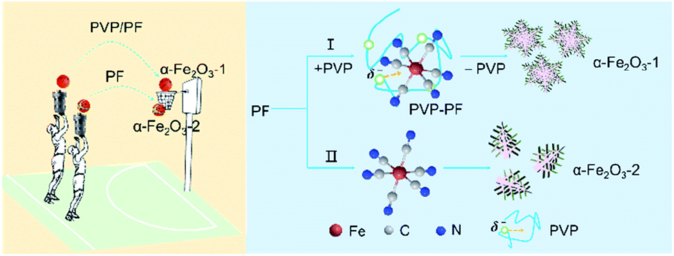
In the present study, PF, a stable complex of Fe(II), was used as iron source. The purpose of this work was to study if our coordination/binding route used in the growth of γ-Ga2O3 can be extended to use in the creation of α-Fe2O3 nanocrystals with improved structure and performance. Our synthesis results are very encouraging, mainly including the following aspects: (1) this new synthesis route gives high yields at milder reaction conditions than previously reported; (2) the as-obtained snowflake-like α-Fe2O3 structure can be well tuned by three parameters, namely, the molar ratio of PVP to PF, the reaction time and the reaction temperature. As shown in Scheme 1, the snowflake-like α-Fe2O3 nanocrystals only can be obtained in the presence of PVP even at the milder reaction conditions (393 K and 6 h). That is to say, the binding of PVP to PF plays a crucial role in the generation of the snowflake-like α-Fe2O3; and especially, (3) the snowflake-like α-Fe2O3 nanocrystals exhibit good shape and size uniformity, with a high specific surface area of 8.86 m2 g−1.
 | ||
| Scheme 1 A schematic representation depicting the binding role of PVP in the formation of the snowflake-like α-Fe2O3 nanocrystals. | ||
Furthermore, our results indicated that the snowflake-like α-Fe2O3 nanocrystals indicate a very high coercivity of 2997 Oe and a remarkable photocatalytic degradation activity for organic dyes such as crystal violet (CV) and rhodamine 6G (R6G), implying application potentials as a magnetic material and a photocatalyst.
In a word, the present study provides a new insight into the link between the formation of supramolecular aggregates and the high-quality synthesis of transition metal oxide nanomaterials. We anticipate that the link will attract scholars from a number of disciplines, including supramolecular chemistry, inorganic chemistry and material science.
Experimental section
Materials
PVP, polytetrafluoroethylene (PTFE) and polyethylene glycol-6000 (PEG-6000) were purchased from Shanghai Chemical Reagent Company. Analytically pure PF, K3[Fe(CN)6], FeCl2 and 30% H2O2 were supplied by Chinese Medical Group Shanghai Chemical Reagent Company, Sinopharm Chemical Reagent Co. Ltd. CV, R6G and methyl orange (MO) were from Aladdin Chemistry Co. Ltd. All other chemicals were of general-purpose reagent grade unless otherwise stated.Preparation of the binary aggregates of PVP and PF
Initially, a series of aggregates of PVP and PF with a range of molar ratios from 0![[thin space (1/6-em)]](https://www.rsc.org/images/entities/char_2009.gif) :1, 1:3 to 1:6 for a repeating unit of PVP to PF were prepared based on the following procedure. For example, PVP (66.6 mg, 0.6 mmol for a repeating unit of PVP) and PF (3H2O, 1267 mg, 3 mmol) were mixed in a flask with 50 mL deionized water and vigorously stirred for 4 h at 333 K. Then, the water was removed by rotary evaporation below this temperature. The remaining solid obtained was washed with water and absolute ethyl alcohol, and dried in a vacuum oven (76 Torr) to constant weight at 333 K. A pale yellow powder was obtained and named as PVP/PF-5 in the light of the 1:5 molar ratio of PVP to PF. The other several samples with the 0:1, 1:3, 1:4 and 1:6 molar ratios of PVP to PF were obtained in the same method and named as PVP/PF-0, -3, -4, and -6, respectively.
:1, 1:3 to 1:6 for a repeating unit of PVP to PF were prepared based on the following procedure. For example, PVP (66.6 mg, 0.6 mmol for a repeating unit of PVP) and PF (3H2O, 1267 mg, 3 mmol) were mixed in a flask with 50 mL deionized water and vigorously stirred for 4 h at 333 K. Then, the water was removed by rotary evaporation below this temperature. The remaining solid obtained was washed with water and absolute ethyl alcohol, and dried in a vacuum oven (76 Torr) to constant weight at 333 K. A pale yellow powder was obtained and named as PVP/PF-5 in the light of the 1:5 molar ratio of PVP to PF. The other several samples with the 0:1, 1:3, 1:4 and 1:6 molar ratios of PVP to PF were obtained in the same method and named as PVP/PF-0, -3, -4, and -6, respectively.
Preparation of a series of brick red precipitates of α-Fe2O3
Initially, 30 mL of 20% (mass ratio of the aggregate to solution) aqueous solutions of the binary aggregate samples was transferred into a sealed Teflon-lined stainless steel autoclave (50 mL) and heated at 393 K for 6 h. Then, several brick red precipitates were gathered by filtration (pH of filtrate, 6.5), washing several times with deionized water and absolute ethyl alcohol, and drying in a vacuum desiccator over phosphoric oxide. However, these reactions gave very low yields (less than 10%), because in the sealed Teflon autoclave there was not sufficient oxygen to oxidize Fe(II) to Fe(III). To improve the reaction yields, we then tried to introduce 3 mL of 30% H2O2 into the Teflon reactor with the volume of the aqueous solutions maintained as a constant (30 mL). It is worth stressing that the reaction yields were greatly improved (higher than 80%). For example, two representative solid samples: α-Fe2O3-1 (82.8%) and -2 (81.9%) were obtained from the direct hydrothermal process of the PVP/PF-5 and PVP/PF-0, respectively.Photocatalytic measurements
The photocatalytic activities of the α-Fe2O3-1 and -2 samples were evaluated by the degradation of several organic dyes: CV, R6G and MO in aqueous solution under visible light irradiation. A 300 W xenon lamp was used as the light source. In a typical experiment, 20 mg of the α-Fe2O3-1 was added to a solution of the dyes (80 mL, 10 mg L−1). Before being irradiated, the solution was stirred in the dark for 30 min at room temperature to establish the adsorption equilibrium between the solution and the photocatalyst, followed by the addition of 1 mL of 30% H2O2. Then, the solution was irradiated under xenon lamp. Finally, the α-Fe2O3-1 catalyst was separated by centrifugation and the supernatant solution was analyzed using a UV-Vis spectrophotometer.Instruments and methods
All solid samples were measured under the same drying conditions. X-ray diffraction (XRD) measurements were performed on a Philips X'Pert Pro X-ray diffractometer (PANalytical, Netherlands) with a scintillation counter detector using a monochromatized Cu Kα radiation source (tube voltage and current were 40 kV and 40 mA) with a wavelength of 0.1542 nm and analyzed in the range of 10° ≤ 2θ ≤ 80°.Crystal morphologies were determined using a Supra 40 field-emission scanning electron microscopy (FE-SEM) operated at 5 kV. Transmission electron microscopy (TEM) and the typical high-resolution transmission electron microscopy (HR-TEM) images and selected area electron diffraction (SAED) patterns were taken on a JEF 2100F field-emission transmission electron microscope performing at 200 kV.
Raman spectra were recorded with a Renishaw InVia Raman Microscope at room temperature with 532 nm laser excitation in the range 100–1800 m−1, with a resolution of 0.6 cm−1. Fourier transform infrared (FT-IR) spectra were recorded on A Bruker Equinox 55 spectrometer with KBr pellets in the range of 400–4000 cm−1 with a resolution of less than 0.09 cm−1.
Thermogravimetry (TG) was performed on a DTGA-60H thermogravimetric analyzer at a constant heating rate of 10.0 K min−1 under a nitrogen atmosphere with a gas flow of 25 mL min−1.
X-ray photoelectron spectroscopy (XPS) measurements were carried out on an ESCALAB 250 spectrometer with Al Kα radiation (1486.6 eV) in ultra-high vacuum (2.00 × 10⁻⁹ Torr). And all of the values of binding energy were referenced to C 1s peak (284.8 eV) with an energy resolution of 0.16 eV.
Nitrogen adsorption/desorption isotherms were recorded using Micromeritics ASAP-2000 Surface Area and Porosimetry System at 77 K. UV-Vis spectra were done with a Shimadzu UV 3600 spectrometer in the range of 200–600 nm, using quartz cells with a 1 cm optical path at room temperature.
Magnetic measurements of the samples were carried out using a Quantum Design (QD, San Diego, USA) Magnetic Property Measurement System (MPMS-7XL) equipped with a superconducting quantum interference device (SQUID) magnetometer.
UV-Vis diffuse-reflectance spectra (UV-Vis DRS) were recorded on a Shimadzu DUV-3700 spectrophotometer in the wavelength between 220 and 2000 nm. A zeta potential and laser particle size analyzer (DLS, NanoBrook 90plus Zeta) was used for zeta potential measurements.
Results and discussion
Microstructure of the α-Fe2O3-1
Fig. 1a shows the X-ray diffraction (XRD) pattern of the α-Fe2O3-1, having a pure rhombohedral structure of α-Fe2O3 phase with a space group of R![[3 with combining macron]](https://www.rsc.org/images/entities/char_0033_0304.gif) c (a = b = 5.0355, c = 13.7471; JCPDS 33-0664).27 No other peaks corresponding to iron hydroxide, γ-Fe2O3 and Fe3O4 could be observed.
c (a = b = 5.0355, c = 13.7471; JCPDS 33-0664).27 No other peaks corresponding to iron hydroxide, γ-Fe2O3 and Fe3O4 could be observed.
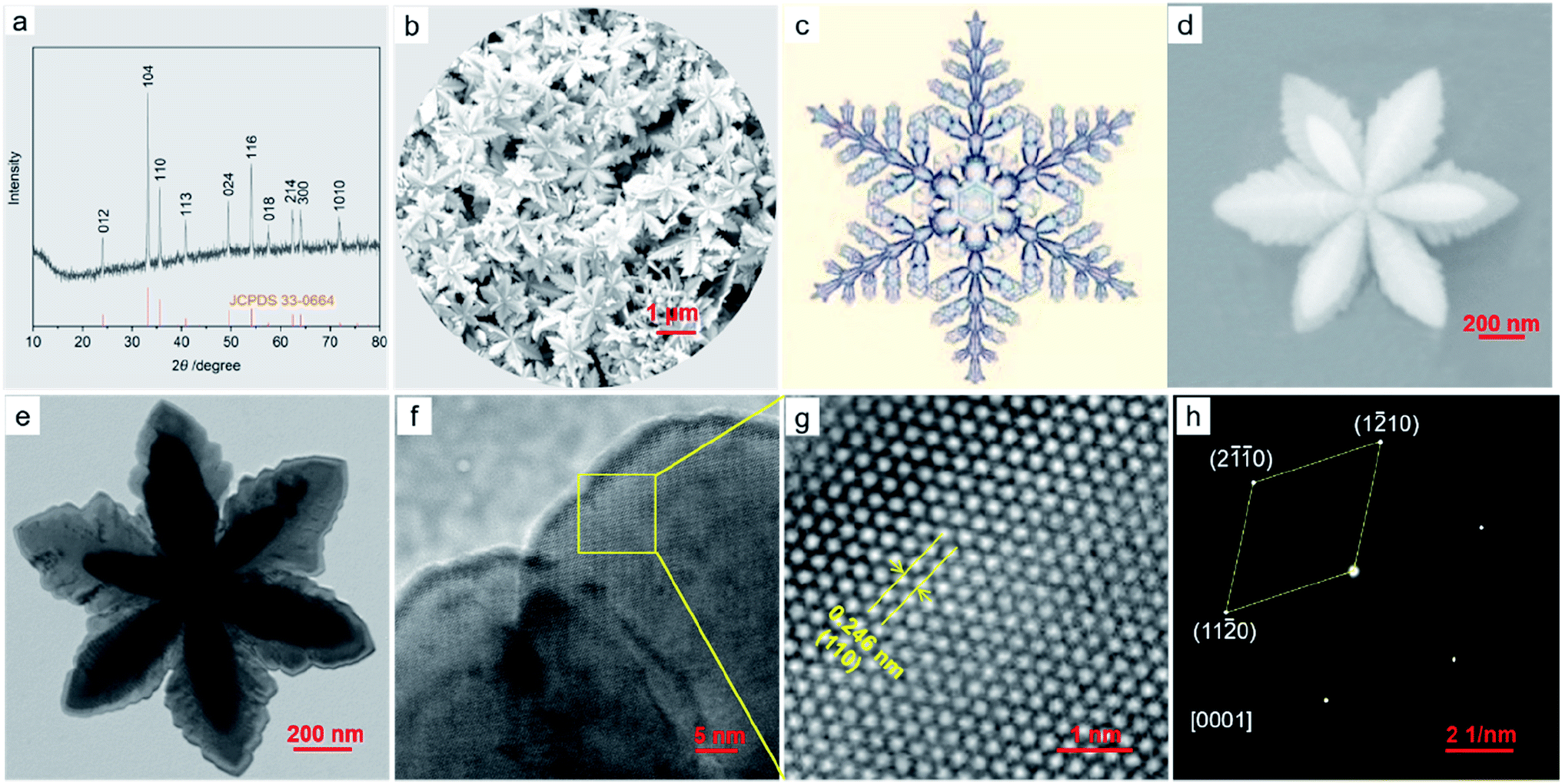 | ||
| Fig. 1 The XRD pattern (a) and FE-SEM image (b) of the α-Fe2O3-1; the picture of a snowflake (c); the FE-SEM image of a single α-Fe2O3-1 nanosnowflake (d); the TEM micrograph of a single α-Fe2O3-1 nanosnowflake (e); the TEM image of a petal edge in (e) and (f); the HR-TEM image (g) and SAED pattern (h) of the yellow box of the α-Fe2O3 in (f). | ||
The FE-SEM image in Fig. 1b illustrates that the α-Fe2O3-1 appears to be made of defined snowflake-like microstructures, as shown in Fig. 1c. The higher magnification FE-SEM image in Fig. 1d clearly reveals that the snowflake-like structure is relatively flat, with an average diameter of about 1.3 μm (Fig. S1, ESI†). Each flower is composed of six petals, with an average width of 350 nm and an average thickness of 20 nm. The TEM image in Fig. 1e indicates that there is a stamen on each petal with a slightly serrated border, and the size of the stamen is smaller than that of the petals. Interestingly, such a highly ordered snowflake-like structure has an almost ideal hexagonal arrangement of petals and stamens.
The HR-TEM image in Fig. 1g for the region in the yellow box of Fig. 1f shows that the snowflake-like nanostructure has the spacing of 0.246 nm between two adjacent lattice fringes, which corresponds to the (110) plane of α-Fe2O3, matching well with the XRD data. The selected-area electron diffraction (SAED) pattern at the same zone as the HR-TEM image proves that the nanosnowflake is single crystalline. Moreover, this pattern corresponding to the [0001] zone axis seems to present a six-fold symmetry around the central spot.
Formation of the α-Fe2O3-1
The absence of an iron hydroxide phase clearly demonstrates that the α-Fe2O3 phase is directly formed in the hydrothermal process through the following steps, as described in eqn (1)–(7).Initially, the PF was partially dissociated into Fe2+ and CN− ions under hydrothermal conditions (eqn (1)). Subsequently, the CN− ions were hydrolyzed into OH− ions (eqn (2)), and the Fe2+ ions were reacted with OH− into Fe(OH)2 (eqn (3)). Then, the Fe(OH)2 was oxidized into Fe(OH)3 through oxygen in the closed-vessel atmosphere (eqn (4)). In view of the fact that there was not sufficient oxygen to oxidize Fe(II) to Fe(III) in this case, 3 mL of 30% H2O2 was added to the Teflon autoclave in order to improve the reaction yields. It should be noted that the introduction of H2O2 led to a much higher yield, such as α-Fe2O3-1 (82.8%) and -2 (81.9%). We consider that it is associated with the oxidation of H2O2 to the dissociation products (Fe2+, CN−) of eqn (1), as depicted in eqn (5) and (6), making the dissociation of PF easier. Finally, the Fe(OH)3 was decomposed into α-Fe2O3 during the hydrothermal process, as depicted in eqn (7).
| [Fe(CN)6]4− ⇌ Fe2+ + 6CN− | (1) |
| CN− + H2O ⇌ HCN + OH− | (2) |
| Fe2+ + 2OH− → Fe(OH)2 | (3) |
| 4Fe(OH)2 + 2H2O + O2 → 4Fe(OH)3 | (4) |
| CN− + H2O2 + H2O → HCO3− + NH3 | (5) |
| 2Fe2+ + H2O2 + 4H2O → 2Fe(OH)3 + 4H+ | (6) |
| 2Fe(OH)3 → α-Fe2O3 + 3H2O | (7) |
To understand the formation process of the α-Fe2O3-1, we have carried out three sets of parallel measurements for estimating the effects of PVP concentrations, hydrothermal temperatures and hydrothermal times.
First, we noticed that the concentration of PVP plays a crucial role in the construction of a complete nanosnowflake-like hexagonal cross-section. As shown in the lower right corner of Fig. 2 (see Fig. S2, ESI†), the higher the concentration of PVP (e.g., the ratio of PVP to PF, 1:4 and 1:3), the lower the completeness of a nanosnowflake. On the contrary, when this ratio is reduced to 1:6 from 1:5 the nanosnowflake-like hexagonal structure remains unchanged. In particular, only the branched nanodendritic-like structure was observed at 393 K for 6 h in the absence of PVP (α-Fe2O3-2, Fig. S3, ESI†). Therefore, the optimal concentration ratio of PVP to PF is recommended to be 1:5 or 1:6.
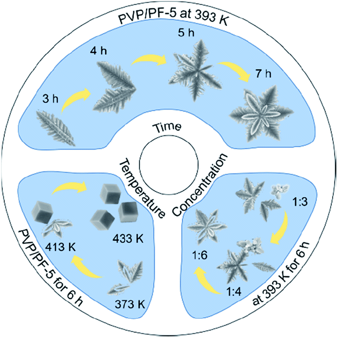 | ||
| Fig. 2 A scheme describing the effect of PVP concentrations, hydrothermal temperatures and hydrothermal times on the formation of α-Fe2O3 nanoparticles. | ||
Based on our recent work on analyzing various interactions including precipitate, coordination and binding equilibria in aqueous solution,19 we consider that the contribution of PVP to the construction of nanoparticles of α-Fe2O3 can be explained as the presence of the binding interaction between the PVP chain and the octahedral complex of Fe(II). The results of several independent experiments confirm this possibility.
Raman spectra in Fig. 3a show that, upon interaction, the Fe–C and Fe–C![[triple bond, length as m-dash]](https://www.rsc.org/images/entities/char_e002.gif) N vibrations28 at 384.2 and 511.4 cm−1, respectively in the free PF has shifted to a higher wavenumber of 388.4 and 515.6 cm−1 in the PVP/PF-5. This result clearly implies that the interaction of PVP with PF results in an enhancement of the Fe–C coordination bonds.
N vibrations28 at 384.2 and 511.4 cm−1, respectively in the free PF has shifted to a higher wavenumber of 388.4 and 515.6 cm−1 in the PVP/PF-5. This result clearly implies that the interaction of PVP with PF results in an enhancement of the Fe–C coordination bonds.
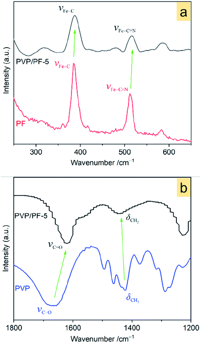 | ||
| Fig. 3 Raman spectra of the PF and PVP/PF-5 (a) and FT-IR spectra of the PVP and PVP/PF-5 (b). The green arrows indicate a shift of the bands from the free components to the binary aggregate. | ||
FT-IR spectra in Fig. 3b indicates that the band at 1667.3 cm−1, assigned to the stretching vibrations of C![[double bond, length as m-dash]](https://www.rsc.org/images/entities/char_e001.gif) O moieties29 in the PVP shifts to a much lower frequency of 1620 cm−1 in the PVP/PF-5. Also, the band at 1422.8 cm−1, corresponding to the CH2 wagging motion30 of PVP, has shifted to a much higher frequency of 1450 cm−1. These observations strongly signify that this interaction leads to a weakness of the CO bond and enhancing of the C–H bond.
O moieties29 in the PVP shifts to a much lower frequency of 1620 cm−1 in the PVP/PF-5. Also, the band at 1422.8 cm−1, corresponding to the CH2 wagging motion30 of PVP, has shifted to a much higher frequency of 1450 cm−1. These observations strongly signify that this interaction leads to a weakness of the CO bond and enhancing of the C–H bond.
Fig. 4a provides an important information concerning the structural environment of the binary aggregate formation between PVP and PF. Obviously, the growth of the aggregate was dominated by the complex PF, since the two strong broad diffraction peaks of PVP completely disappeared upon aggregation. In addition, two significant diffraction characters were observed: the appearance of a new diffraction peak at 2θ of 24.8° and the shift of the strongest signal of PF at 31.9° toward a lower 2θ angle. Also, the SEM images (Fig. 4b and c) of PF and the PVP/PF-5 have a very large difference in particle size and shape.
 | ||
| Fig. 4 XRD patterns of free PVP, PF and the PVP/PF-5 (a) and SEM images of PF (b) and PVP/PF-5 (c). | ||
The results of Raman spectra, FT-IR spectra and XRD patterns effectively demonstrate that the presence of the ion–dipole interaction between PVP and PF leads to an increase in the stability of the complex due to the enhancement of the Fe–C coordination bonds. The differential thermogravimetric analysis also supports this observation, since there is an increase of decomposition temperature of 22 K from the free PF to the PF in the PVP/PF-5 (Fig. S4, ESI†). We therefore propose that this interaction can be described as a binding behavior of the polymer PVP to the complex PF, as illustrated in Fig. 5.
 | ||
| Fig. 5 Proposed ion–dipole interactions between PVP and PF. The purple arrows denote the directions of electronic transfers. | ||
The consequence of the binding interaction is significant because it allows us to evaluate the effect mechanism of PVP on the formation of the α-Fe2O3 nanosnowflakes. On the one hand, the binding of PVP to PF makes the generation of Fe2+ ions from eqn (1) difficult. On the other hand, it is also possible that the Fe2+ ions into the solution were once again bound by PVP. Both these factors will result in the nucleation and growth process elongation of α-Fe2O3, thereby favoring the transition from an initially dendritic structure to a snowflake structure with a truly planar interface. As seen from Fig. 2, the integrity of the α-Fe2O3 nanosnowflake structure is directly dependent upon the concentration of PVP. This finding is different from several previous studies on the formation of single-crystalline α-Fe2O3 with hierarchical snowflake-shaped structures using K3[Fe(CN)6] as the raw material.14–16 In particular, it should be mentioned that Zhang and his collaborators obtained α-Fe2O3 nanotubes using a combination of PF and H2O2 as the raw materials by a similar hydrothermal treatment (433 K and 100 min) in the absence of PVP.31 These observations and comparisons highlight the importance of PVP for the formation of the α-Fe2O3 nanosnowflake structure.
The other difference between this work and previous approaches is that the iron source is a Fe(II) complex of CN− ions rather than a Fe(III) complex of CN− ions or a mixture of Fe(II) and Fe(III) complexes of CN− ions. We noticed that no snowflake-shaped structure of α-Fe2O3 was obtained, when PF was substituted by K3[Fe(CN)6] and FeCl2 (Fig. 6) at the same conditions as the α-Fe2O3-1. This emphasizes the importance of slow release and oxidation of Fe(II) ions in the reaction system.
 | ||
| Fig. 6 XRD patterns and FE-SEM images of several α-Fe2O3 samples obtained by the same method as the α-Fe2O3-1, but either (A) PF was replaced by different Fe sources: (a1) FeCl2, (a2) K3[Fe(CN)6] or (B) PVP was replaced by different hosts: (b1) PEG-6000 and (b2) PTFE. | ||
Also, using the same hydrothermal method, we further investigated the effect of several other polymers on the structure of α-Fe2O3. As can be seen from Fig. 6, when the PVP in the aggregate PVP/PF-5 was substituted by PTFE and PEG-6000, α-Fe2O3 dendritic structures (thickness, about 100 nm) were formed. This result may be a reflection that the significance of a suitable choice of polymers to obtain the snowflake-shaped structure of α-Fe2O3.
Second, the effect of hydrothermal reaction temperatures was explored, and the result is shown in Fig. 1 and 2. It is clear that when the temperature was increased from 373 to 433 K, the series of samples obtained by a hydrothermal process of PVP/PF-5 for 6 h consist of pure rhombohedral phase of α-Fe2O3 (Fig. S5, ESI†). However, the morphology of the samples was changed continuously in the temperature range from an incomplete snowflake-like structure at 373 K (Fig. 2), to a complete snowflake-like structure at 393 K (Fig. 1), then to a hybrid structure consisting of an incomplete snowflake-like structure at 413 K and a cubic structure, and finally to uniform cubes at 433 K (Fig. 2). Such a continuous configuration transition is quite interesting in the sense that it is one of the few known results stating that there is a significant evolution from a flower-like structure to a cubic structure in the surface feature of α-Fe2O3. In a previous work, we noticed that the structural transformation of polyhedral crystals of a-Fe2O3 was easily controlled by sintering times.13 We therefore believe that these examples provide useful information on understanding of controlled synthesis of α-Fe2O3 nanocrystals.
Third, to clarify the construction process of the snowflake-shaped structure, we further evaluated the effect of hydrothermal reaction times. Fig. 7 shows the XRD patterns of several samples derived from a hydrothermal process of the PVP/PF-5 at 393 K for 3, 4, 5 and 7 h. All of the reflection peaks in the samples can be readily indexed to a rhombohedral single phase of α-Fe2O3. We noticed that with the extension of reaction time from 3 to 5 h, the relative intensity of the peaks due to (104) and (110) reflections was increased. And finally, the relative intensity of the two sets of peaks is roughly stable at 6 (Fig. 1a) and 7 h. It is known that the type and amount of structural disorder can greatly affect the relative intensity of the diffraction peaks. Thus, this observation clearly indicates a time-dependent growth along the (104) and (110) planes for the complete snowflake-like structure. The SEM images in Fig. 1 and 2 reinforce this from the other side. There is a clear time-dependent formation process of the structural features from a petal at 3 h, to a combination of two or more petals at 4 and 5 h, and finally to a complete assembly of six petals at 6 and 7 h, as seen from Fig. 1, 2 and S6 (ESI†).
 | ||
| Fig. 7 XRD patterns of the α-Fe2O3 samples prepared using a hydrothermal process of the PVP/PF-5 at 393 K for 3, 4, 5 and 7 h, respectively. | ||
Combining the results above, we can conclude that all the three parameters: hydrothermal reaction temperatures, hydrothermal reaction times, and especially PVP concentrations play a significant part in the creation of nanostructured α-Fe2O3 snowflakes.
Magnetic properties of the α-Fe2O3-1
The magnetic behavior analysis of nanostructured α-Fe2O3 is of significance for practical applications.32 Fig. 8a displays the magnetic susceptibility (χ, cm3 g−1) of the α-Fe2O3-1 in an applied field (H = 500 Oe) in the temperature range of 5 to 310 K. It clearly shows a characteristic magnetic pattern of α-Fe2O3,33 revealing a high temperature dependence of the susceptibility. The curve in Fig. 8b is the differential magnetic susceptibility (dχ/dT), and the strong sharp peak at 232 K is considered as the Morin transition temperature (TM, K),34 which is much lower than that of normal bulk hematite.35 It is reported that bulk hematite exhibits the Morin transition at about 260 K from a low-temperature antiferromagnetic state to a weak ferromagnetic state.36 Such a significant decrease of about 30 K in TM is agreement with the report of Hu and Wang and their colleagues on hematite dendrites.14 We suggest that this phenomenon may be connected with lattice strain and defects in the dendrites, especially with the decrease in size of the hematite microstructure.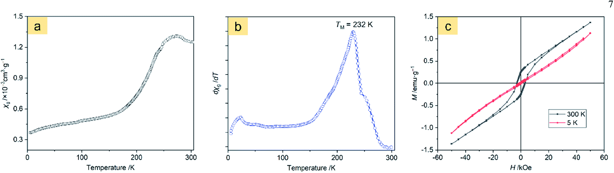 | ||
| Fig. 8 Magnetic measurements of the α-Fe2O3-1: (a) temperature dependence of magnetic susceptibility at 500 Oe, (b) differential magnetic susceptibility at 500 Oe, and (c) field dependence of magnetization at 5 and 300 K. | ||
The room temperature magnetic properties of the α-Fe2O3 snowflakes and dendrites were explored by measuring the magnetization (M) hysteresis loop using a vibrating sample magnetometer.
Fig. 8c and S7 (ESI†) show the M–H loops of the α-Fe2O3-1 and α-Fe2O3-2 at 5 and 300 K, indicating weak ferromagnetic behaviour at 300 K for this set of samples, which is in agreement with the observations previously reported.43 It is obvious that the magnetizations of the two samples do not saturate and still increase with applied magnetic field in the available field range, possibly due to the presence of large shape anisotropy in the materials. The small loops at low fields and the unsaturated magnetizations even for a high applied magnetic field of 50 kOe reveal a canted antiferromagnetic structure. The canting of spins may be due to anisotropies such as the Dzyaloshinsky–Moriya antisymmetric exchange interaction.44
The maximum magnetizations (Mm) of the snowflake-like and dendrite-like structures at 50 kOe at 300 K are 1.37 and 1.30 emu g−1, respectively. The remanent magnetizations (Mr) at 300 K were determined to be 0.26 and 0.22 emu g−1 for the snowflake-like and dendrite-like structures, respectively, from the magnetization curves. All these values are comparable to those of other works,14,37–42 as seen in Table 1. However, the two samples show much higher coercivities (Hc, 2997 Oe for the snowflake structure and 2749 Oe for the dendrite-like structure) compared to those reported by others (no higher than 1610 Oe, see Table 1). One possible reason for the much higher coercivities may be the presence of defects in the crystal structures.45 The other possible reason may be due to the interfacial roughness of the α-Fe2O3-1 and -2, because the interfacial roughness can provide more interfacial area and spin dispersion, thereby causing enhanced coercivity.46 It is interesting to note that higher coercivities were obtained in the two nanostructures since a higher coercivity is an important factor for high-density information storage. In particular, a higher coercivity occurred in the α-Fe2O3-1 nanostructure.
| Samples | Mm/emu g−1 | Hc/Oe | Mr/emu g−1 |
|---|---|---|---|
| α-Fe2O3-1 | 1.37 | 2997 | 0.26 |
| α-Fe2O3-2 | 1.30 | 2749 | 0.22 |
| Micro-pine dendrites14 | — | 1510 | — |
| Dendrites37 | 0.43 | 224 | 0.05 |
| Dendrites38 | — | 1610 | — |
| Snowflakes39 | 2.66 | 134 | 0.67 |
| Dendritic micro-crystal40 | 1.05 | 163 | — |
| Dendrites41 | 2.53 | 157 | 0.20 |
| Single-layered snowflakes41 | 1.38 | 239 | 0.12 |
| Double-layered snowflakes41 | 0.83 | 436 | 0.24 |
| Hyperbranched dendrites42 | 0.48 | 1364 | 0.17 |
| Primary and secondary branched dendrites42 | 0.46 | 1108 | 0.16 |
| Primary branched dendrites42 | 0.44 | 1104 | 0.17 |
| Slightly branched dendrites42 | 0.48 | 1102 | 0.13 |
This result was unexpected and is not easy to explain. It seems possible that it is related to the difference in electronic structures of Fe(III) between the two materials.
Fig. 9a displays the Fe 2p XPS spectrum of the α-Fe2O3-1, in which the 2p peaks appear at 711.3 and 725.1 eV with a small satellite peak at about 719.4 eV. The presence of the satellite peak is a reflection of the characteristic feature of Fe(III) in Fe2O3.47,48 The 2p peaks of the α-Fe2O3-2 with a branched nanodendritic-like structure appear at 710.7 and 724.0 eV, as seen in Fig. 9b. These results not only further confirm the formation of Fe2O3, but also clearly indicate that there is an observable difference of binding energies (0.6–1.1 eV) between the α-Fe2O3 samples. Such a difference is a reflection of the difference in electronic densities of the electron shells of Fe(III), and the higher binding energy of core level in Fe(III) in the α-Fe2O3-1 than in the α-Fe2O3-2 may be an important factor with respect to the magnetic difference between the two α-Fe2O3 materials.
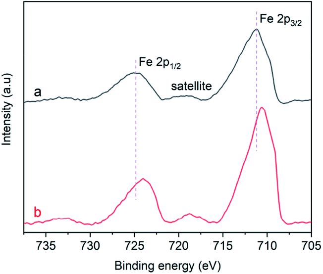 | ||
| Fig. 9 Fe2p XPS spectra of the α-Fe2O3 samples: (a) α-Fe2O3-1 and (b) α-Fe2O3-2. | ||
It was reported that the atoms in an α-Fe2O3 rhombohedral structure exhibit a C3v symmetry and have two different kinds of Fe–O bonds.49 The coordination numbers of oxygen ions andiron ions are 6 and 4, respectively, and the oxygen ions were situated along the (001) plane.50 Such a clear difference between the electronic structures strongly suggest that there is a significant difference of the Fe–O bonds in the two α-Fe2O3 microstructures. In other words, the Fe(III) ions in the nanodendritic-like structure seem to exhibit a stronger binding affinity for oxygen ions than in the nanosnowflake-like structure.
Although the explanation of this phenomenon remains unclear, we speculate that it may be associated with the Jahn–Teller effect:51 when an orbital state (t52ge0g) of the Fe(III) ion in an oxygen octahedral field is degenerate for symmetry reasons, the oxygen ligands will experience forces driving the coordination system to a lower-symmetry configuration, lowering its energy. It should be reasonable that the nanodendritic-like structure may provide a larger Jahn–Teller distortion than the nanosnowflake-like structure.
Photocatalytic activity of the α-Fe2O3-1
In view that the α-Fe2O3 nanosnowflakes possess a sawtooth-like surface profile, we consider that this structure may have a large surface area, thereby providing a high capability for adsorbing organic pollutants.The Brunauer–Emmett–Teller (BET)52 specific surface areas of the α-Fe2O3-1 and -2 were determined to be 8.86 and 4.29 m2 g−1, respectively, based on the nitrogen sorption isotherms (Fig. 10). It should be noticed that both the isotherms exhibit the same type of IV/H1 profile.53 The Barrett–Joyner–Halenda (BJH)54 model shows that the α-Fe2O3-1 and -2 have an average pore diameter of 8.70 and 24.6 nm, respectively. It is clear that the snowflake-like structure exhibits a much higher BET specific surface area and a much lower BJH average pore diameter than the dendrite-like structure. Such a large difference in microstructures permits us to estimate the relationship between the microstructure and the photocatalytic properties of α-Fe2O3 nanomaterials.
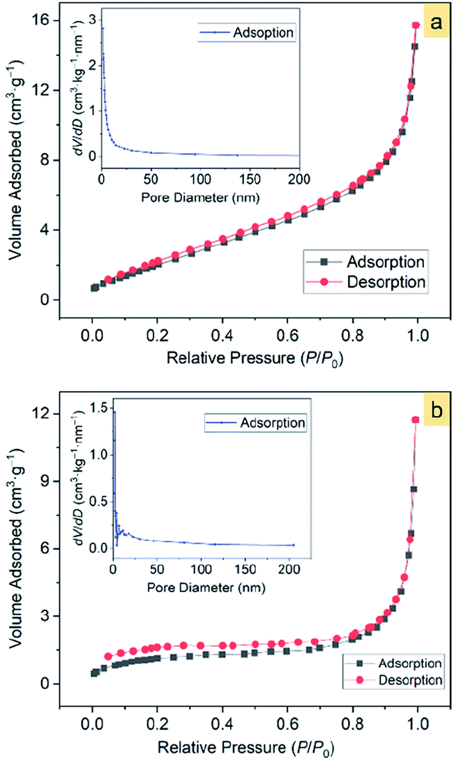 | ||
| Fig. 10 The N2 adsorption–desorption isotherms of α-Fe2O3 samples: (a) α-Fe2O3-1 and (b) α-Fe2O3-2. The insets show the corresponding pore-size distribution. | ||
To demonstrate the photocatalytic oxidation activity of the α-Fe2O3-1 for the degradation of organic pollutants, we performed experiments on the photocatalytic oxidation degradation of CV, R6G and MO.
Fig. 11a shows the adsorption spectra of the series of CV solutions (80 mL, 10 mg L−1) in the presence of the α-Fe2O3-1 (20 mg) with H2O2 (1 mL of 30%) under visible light with different irradiation times from 0 to 80 min. The maximum absorption peak of CV centers at approximately 590 nm before irradiation. When the light was turned on, an irradiation of 10 min resulted in a steep decrease of the maximum absorption from 1.62 to 0.25. Then, it was gradually decreased with the increased irradiation time from 10 min to 60 min, and finally reached a value close to zero for 80 min. Also, these curve profiles show a new peak in the wavelength of 374 nm, and we propose that it is due to the formation of intermediates of CV oxidation by H2O2. These results clearly reveal that the CV molecules were almost completely degraded within 80 min by photocatalysis of the α-Fe2O3-1.
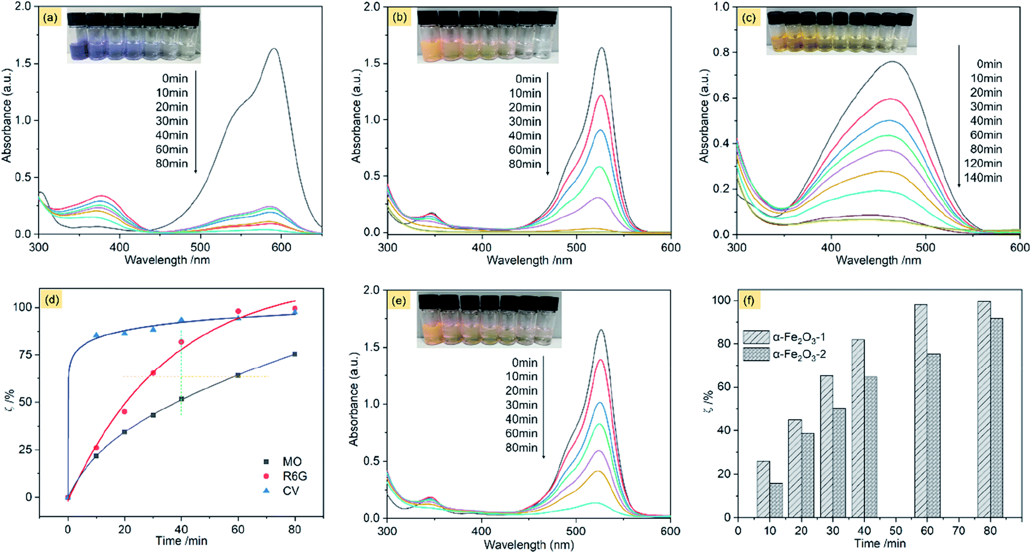 | ||
| Fig. 11 Absorption spectra of CV (a), R6G (b) and MO (c) on the α-Fe2O3-1 in the presence of H2O2 with different illumination times: 0–80 min; (d) photodegradation of several different organic dyes on the α-Fe2O3-1; (e) absorption spectra of R6G on the α-Fe2O3-2 in the presence of H2O2 with different illumination times: 0–80 min; and (f) the photodegradation difference of R6G on the α-Fe2O3-1 and -2 at different illumination times: 0–80 min. | ||
The photocatalytic efficiency (ζ, %) of the α-Fe2O3-1 for the oxidation of CV by H2O2 in water can be represented by eqn (8).
| ζ = (C0 − C)/C0 × 100% | (8) |
In this equation, C0 is the initial concentration of CV when the visible light is turned off, while C is the real-time concentration of CV under the visible light irradiation. The ζ value of the α-Fe2O3-1 for CV is 97.6% under an irradiation of 80 min in the light of the equation.
Fig. 11b shows the adsorption spectra of R6G solutions, with the maximum absorption peak centered at 526 nm before irradiation. We notice that at the same illumination time of 80 min, the absorption peak of R6G almost disappeared, with a ζ value of 99.6%. It means that the catalyst has a similar photocatalytic activity for the two organic dyes, namely, CV and R6G. The high similarity may be related to the fact that the two organic dyes are hydrophilic and cationic with the same charge but different sizes.
This speculation is supported by the experimental observation of an anionic dye MO. Fig. 11c shows the adsorption spectra of MO solutions, with the maximum absorption peak centered at 464 nm before irradiation. Our data indicate that the ζ value of the α-Fe2O3-1 for the oxidation of MO was greatly decreased to 75.4% at the illumination time of 80 min. Moreover, only a ζ value of 92.0% was obtained even at the illumination time of 140 min.
These results strongly suggest that the snowflake-like structure possesses a much higher catalytic activity for cationic dyes such as CV and R6G than for anion dyes such as MO, thereby showing a unique catalytic selectivity for two kinds of dyes with opposite charges. The zeta potentials of the α-Fe2O3-1 and -2 were determined to be −44.12 and −37.19 mV at pH 7, suggesting that the catalysts have good stability in solution. Further, the electronegativity of the materials enhances from the α-Fe2O3-2 to the α-Fe2O3-1, which is consistent with the fact that the photocatalytic performance of the α-Fe2O3-1 is slightly higher than that of the α-Fe2O3-2 because the stronger the electronegativity, the stronger the ability to attract cationic dyes with positive charges. As shown in Fig. S8 (ESI†), the UV-Vis absorption peak of CV molecules at 590 nm in the mixed dyes (MO and CV) solutions on the α-Fe2O3-1 in the presence of H2O2 was gradually weakened under the visible light irradiation from 0 to 80 min. However, the characteristic absorption peak of MO did not show significant changes in 80 min. This observation strongly implies that the α-Fe2O3-1 shows a photocatalytic selectivity for the two kinds of organic dyes.
Furthermore, the effect of illumination times on the ζ value was evaluated carefully. As can be seen in Fig. 11d, the degradation of MO is considerably gentle, while the degradation of R6G was much faster (see the orange line) at the same value of ζ, and much higher (see the green line) at the same illumination time. Particularly, the degradation gradient of CV was at first abrupt (from 0 to 10 min), and then became smooth (from 10 to 80 min). In short, this figure well illustrates the oxidation degradation difference of CV, R6G and MO on the α-Fe2O3-1 catalyst. This result may be a reflection of structural differences of the organic dyes.
Also, we examined the photocatalytic degradation of R6G on the α-Fe2O3-2 under the same conditions. As shown in Fig. 11e, a ζ value of 92.1% was obtained under an irradiation of 80 min.
Fig. 11f shows that the α-Fe2O3-1 with a snowflake nanostructure always gives a slightly higher catalytic activity for the oxidation R6G than the α-Fe2O3-2 with a dendritic nanostructure at any illumination time in the time range tested (0–80 min). Fig. S9a (ESI†) clearly shows that the α-Fe2O3 catalysts have a wide absorption band in the wavelength range of 400–700 nm, which facilitates a strong absorption of visible light. As we know, the band-gap energy is one of the most important characteristics of materials as catalysts. The narrow band-gap of the α-Fe2O3 nanocrystals (band-gap energy: 1.94 eV for the α-Fe2O3-1 and 2.01 eV for the α-Fe2O3-2, see Fig. S9b ESI†) is good for the electron transition from valence band to conduction band, thereby showing visible light photocatalytic activity for R6G. Also, we noticed that a slight difference of band-gap energy occurs between the α-Fe2O3 samples. There is a small increase from the α-Fe2O3-1 to the α-Fe2O3-2, which may be one reason why the two catalysts exhibit a slight difference in their photocatalytic activities. Moreover, this figure emphasizes that there is only a little difference in the photocatalytic activity of the two catalysts at the illumination times. In particular, both of them exhibit high catalytic activities (ζ > 90%) for R6G, which is comparable to and better results reported previously. For example, Xie's group reported that α-Fe2O3 dendritic crystals showed a ζ value of about 50% for rhodamine-B under visible-light irradiation of 80 min.55 For another example, Xia and his co-workers found that 90% of MB could be photodegraded by dendritic α-Fe2O3 micropines after irradiation for 150 min.56
It is well-known that Fe3+ plays a very important role in photo-Fenton reaction through a redox cycle from Fe(III) ions to Fe(II) ions, and then to hydroxyl radicals (·OH),57 as shown in Fig. 12. Since the surface of α-Fe2O3 possesses partial negative charges (δ−),58 cationic dyes such as CV could be efficiently adsorbed on the surface of the catalyst via an ion–dipole interaction between the negative charges and the N atoms with partial positive charges (δ+) on the CV. The electrons and holes were located in the conduction band (CB) and valence band (VB) of the α-Fe2O3 catalyst, respectively. They can interact with H2O2 molecules near the surface of α-Fe2O3, resulting in the generation of highly active ·OH through a process from eqn (9)–(11). Initially, Fe(III) ions interact with H2O2 to produce Fe(III)–OOH2+ coordination intermediates. Subsequently, the intermediates were decomposed into Fe(II) ions. Then, the Fe(II) ions were oxidized into Fe(III) by H2O2, leading to the formation of ·OH. Finally, the CV molecules were oxidized by the ·OH radicals into small molecules such as CO2 and H2O, as described in eqn (12). The anionic dye MO has a lower ζ value than CV and R6G, possibly because it could not efficiently be adsorbed on the surface of the catalyst.
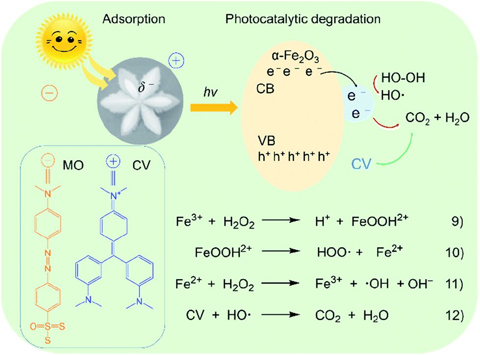 | ||
| Fig. 12 Possible schematic illustration of photocatalytic oxidation degradation of organic dyes on the α-Fe2O3-1 catalyst. | ||
The photocatalytic experiments of the α-Fe2O3-1 nanomaterial in the absence of H2O2 were made, and the results are shown in Fig. S10 (ESI†). We found that the catalytic performance of the α-Fe2O3-1 for the degradation of R6G in the absence of H2O2 is much weaker than in the presence of H2O2. This result may further support the photocatalytic mechanism, since it will be very difficult to generate highly active ·OH radicals without H2O2 molecules near the surface of α-Fe2O3-1, thereby leading to low photocatalytic performance.
Conclusions
In this study, we reported an improved hydrothermal route to construct high-quality α-Fe2O3 nanocrystals with a snowflake-like microstructure. In this project, binary supramolecular aggregates of PVP and PF with different initial molar ratios were used as the precursors of the α-Fe2O3 nanostructures. The snowflake-like α-Fe2O3 microstructure exhibits high monodispersity, good size and shape uniformity. This synthetic route shows a better performance in terms of higher yields, lower reaction temperatures and shorter reaction times compared to those of other reported studies. In particular, our results show that the constitution of the aggregates, namely, the molar ratio of PVP to PF, plays a key part in creating a complete snowflake structure. Moreover, we notice that the snowflake-like α-Fe2O3 nanostructure indicates a significantly higher coercivity in comparison with those reported in the literature. This finding may provide an indication of potential performance for memory devices. Furthermore, the α-Fe2O3 nanosnowflakes display an improved photocatalytic activity for the oxidation degradation of several organic dyes: CV, R6G and MO. It is our hope that the present strategy provides a new clue for the design and synthesis of high-quality inorganic metal oxide nanomaterials.Conflicts of interest
There are no conflicts of interest to declare.Acknowledgements
This work was supported by the National Synchrotron Radiation Laboratory (No. UN2016LHJJ) and the Natural Science Foundation of Anhui Province (No. 1508085MB30).References
- (a) Y. Jiao, Y. Liu, F. Y. Qu and X. Wu, CrystEngComm, 2014, 16, 575 RSC; (b) M. Mishra and D.-M. Chun, Appl. Catal., A, 2015, 498, 126 CrossRef CAS.
- J. Chang, J. Q. Wang, J. Qu, Y. V. Li, L. J. Ma, L. F Wang, X. X. Wang and K. Pan, Environ. Sci.: Nano, 2016, 3, 894 RSC.
- F. X. Liang, L. Liang, X. Y. Zhao, X. W. Tong, J. G. Hu, Y. Lin, L. B. Luo and Y. C. Wu, RSC Adv., 2018, 8, 31121 RSC.
- (a) L. Zhang, H. B. Wu, S. Madhavi, H. H. Hng and X. W. Lou, J. Am. Chem. Soc., 2012, 134, 17388 CrossRef CAS; (b) L. L. Li, H. B. Wu, L. Yu, S. Madhavi and X. W. Lou, Adv. Mater. Interfaces, 2014, 1, 1400050 CrossRef; (c) Y. Z. Wang, J. S. Han, X. X. Gu, S. Dimitrijev, Y. L. Hou and S. Q. Zhang, J. Mater. Chem. A, 2017, 5, 18737 RSC.
- X. Zhang, Y. A. Niu, Y. Li, X. M. Hou, Y. B. Wang, R. Bai and J. P. Zhao, Mater. Lett., 2013, 99, 111 CrossRef CAS.
- (a) L. Li, Y. Yu, F. Meng, Y. Tan, R. J. Hamers and S. Jin, Nano Lett., 2012, 12, 724 CrossRef CAS; (b) W. H. Zhu, J. Winterstein, I. Maimon, Q. Y. Yin, L. Yuan, A. N. Kolmogorov, R. Sharma and G. W. Zhou, J. Phys. Chem. C, 2016, 120, 14854 CrossRef CAS.
- (a) G. X. Gao, L. Yu, H. B. Wu and X. W. Lou, Small, 2013, 9, 1741 Search PubMed; (b) T. P. Almeida, M. W. Fay, T. W. Hansen, Y. Zhu and P. D. Brown, CrystEngComm, 2014, 16, 1540 RSC.
- (a) Z. Y. Wang, D. Y. Luan, S. Madhavi, C. M. Li and X. W. Lou, Chem. Commun., 2011, 47, 8061 RSC; (b) E. M. Verdugo, Y. Xie, J. Baltrusaitis and D. M. Cwiertny, RSC Adv., 2016, 6, 99997 RSC.
- (a) W. R. Cheng, J. F. He, T. Yao, Z. H. Sun, Y. Jiang, Q. H. Liu, S. Jiang, F. C. Hu, Z. Xie, B. He, W. S. Yan and S. Q. Wei, J. Am. Chem. Soc., 2014, 136, 10393 CrossRef CAS; (b) L. L. Li, H. B. Wu, L. Yu, S. Madhavi and X. W. Lou, Adv. Mater. Interfaces, 2014, 1, 1400050 CrossRef.
- (a) B. Wang, J. S. Chen, H. B. Wu, Z. Y. Wang and X. W. Lou, J. Am. Chem. Soc., 2011, 133, 17146 CrossRef CAS; (b) S. Sundar, R. Mariappan, K. Min and S. Piraman, RSC Adv., 2016, 6, 77133 RSC.
- L. L. Wang, T. Fei, Z. Lou and T. Zhang, ACS Appl. Mater. Interfaces, 2011, 3, 4689 CrossRef CAS.
- (a) J. S. Chen, T. Zhu, C. M. Li and X. W. Lou, Angew. Chem., Int. Ed., 2011, 50, 650 CrossRef CAS; (b) P. Du, L. X. Song, J. Xia, Y. Teng and Z. K. Yang, J. Mater. Chem. A, 2014, 2, 11439 RSC; (c) C. Y. Zhang, S. Liu, T. T. Chen, Z. H. Li and J. . C. Hao, Chem. Commun., 2019, 55, 7370 RSC; (d) L. Zhang, H. B. Wu, R. Xu and X. W. Lou, CrystEngComm, 2013, 15, 933 Search PubMed.
- L. B. Wang, L. X. Song, Z. Dang, J. Chen, J. Yang and J. Zeng, CrystEngComm, 2012, 14, 3355 RSC.
- M. H. Cao, T. F. Liu, S. Gao, G. B. Sun, X. L. Wu, C. W. Hu and Z. L. Wang, Angew. Chem., 2005, 117, 4269 CrossRef.
- J. M. Gu, S. H. Li, E. B. Wang, Q. Y. Li, G. Y. Sun, R. Xu and H. Zhang, J. Solid State Chem., 2009, 182, 1265 CrossRef CAS.
- (a) C. Jia, Y. Cheng, F. Bao, D. Q. Chen and Y. S. Wang, J. Cryst. Growth, 2006, 294, 353 CrossRef CAS; (b) K. He, C. Y. Xu, L. Zhen and W. Z. Shao, Mater. Lett., 2008, 62, 739 CrossRef CAS.
- (a) Z. Liu, C. Y. Chiang, W. Li and W. Z. Zhou, Chem. Commun., 2015, 51, 9350 RSC; (b) S. Majumder, B. Saha, S. Dey, R. Mondal, S. Kumar and S. Banerjee, RSC Adv., 2016, 6, 59907 RSC.
- S. Majumder, S. Pal, S. Kumar and S. Banerjee, Mater. Today, 2017, 4, 5620 Search PubMed.
- Z. Yang, L. X. Song, Y. Q. Wang, M. M. Ruan, Y. Teng, J. Xia, J. Yang, S. S. Chen and F. Wang, J. Mater. Chem. A, 2018, 6, 2914 RSC.
- Y. Q. Wang, L. X. Song, Y. Teng, F. Wang, W. P. Wang, M. M. Ruan, Z. Yang and Z. Y. Xu, J. Mater. Chem. C, 2019, 7, 1477 RSC.
- (a) T. Sun and J. Y. Ying, Nature, 1997, 389, 704 CrossRef CAS; (b) L. Bai, F. Wyrwalski, C. Machut, P. Roussel, E. Monflier and A. Ponchel, CrystEngComm, 2013, 15, 2076 RSC.
- D. Amara, J. Grinblat and S. Margel, J. Mater. Chem., 2012, 22, 2188 RSC.
- S. Noël, B. Léger, A. Ponchel, K. Philippot, A. Denicourt-Nowicki, A. Roucoux and E. Monflier, Catal. Today, 2014, 235, 20 CrossRef.
- (a) A. Lannoy, R. Bleta, C. Machut-Binkowski, A. Addad, E. Monflier and A. Ponchel, ACS Sustainable Chem. Eng., 2017, 5, 3623 CrossRef CAS; (b) R. Bleta, S. Noël, A. Addad, A. Ponchel and E. Monflier, RSC Adv., 2016, 6, 14570 RSC.
- M. Lin, H. R. Tan, J. P. Y. Tan and S. Q. Bai, J. Phys. Chem. C, 2013, 117, 11242 CrossRef CAS.
- K. M. Koczkur, S. Mourdikoudis, L. Polavarapu and S. E. Skrabalak, Dalton Trans., 2015, 44, 17883 RSC.
- (a) X. L. Zhang, C. H. Sui, J. Gong, Z. M. Su and L. Y. Qu, J. Phys. Chem. C, 2007, 111, 9049 CrossRef CAS; (b) A. E. Green, C.-Y. Chiang, H. F. Greer, A. Waller, A. Ruszin, J. Webster, Z. Y. Niu, K. Self and W. Z. Zhou, Cryst. Growth Des., 2017, 17, 800 CrossRef CAS.
- W. P. Griffith and G. T. Turner, J. Chem. Soc. A, 1970, 858 RSC.
- S. G. Kazarian and G. G. Martirosyan, Int. J. Pharm., 2002, 232, 81 CrossRef CAS.
- (a) V. D. Moravec and C. C. Jarrold, J. Chem. Phys., 2000, 113, 1035 CrossRef CAS; (b) I. M. Mirza, A. K. Sarfraz and S. K. Hasanain, Acta Phys. Pol., A, 2014, 126, 1280 CrossRef.
- L. M. Song, S. J. Zhang, B. Chen, J. J. Ge and X. C. Jia, Colloids Surf., A, 2010, 360, 1 CrossRef CAS.
- M. Tadic, M. Panjan, V. Damnjanovic and I. Milosevic, Appl. Surf. Sci., 2014, 320, 183 CrossRef CAS.
- G. B. Sun, B. X. Dong, M. H. Cao, B. Q. Wei and C. W. Hu, Chem. Mater., 2011, 23, 1587 CrossRef CAS.
-
(a) F. J. Morin, Phys. Rev., 1950, 78, 819 CrossRef CAS;
(b) F. P. Chmiel, N. Waterfield Price, R. D. Johnson, A. D. Lamirand, J. Schad, G. van der Laan, D. T. Harris, J. Irwin, M. S. Rzchowski, C.-B. Eom and P. G. Radaelli, Nat. Mater., 2018, 17, 581 CrossRef.
- F. Jiao, A. Harrison, J. C. Jumas, A. V. Chadwick, W. Kockelmann and P. G. Bruce, J. Am. Chem. Soc., 2006, 128, 5468 CrossRef CAS.
- (a) D. J. Simkin and R. A. Bernheim, Phys. Rev., 1966, 153, 621 CrossRef; (b) M. Tadic, L. Kopanja, M. Panjan, S. Kralj, J. Nikodinovic-Runic and Z. Stojanovic, Appl. Surf. Sci., 2017, 403, 628 CrossRef CAS.
- F. Beshkar, H. Jahangiri and M. Mouasavi-Kamazani, J. Mater. Sci., 2016, 27, 12869 CAS.
- Q. T. Pan, K. Huang, S. B. Ni, F. Yang, S. M Lin and D. Y. He, J. Phys. D: Appl. Phys., 2009, 42, 015417 CrossRef.
- H. F. Liang and Z. C. Wang, Mater. Lett., 2010, 64, 2410 CrossRef CAS.
- J. Liang, L. Li, W. M. Song, J. Z. Fang, M. Luo and Y. P. Li, Cryst. Res. Technol., 2010, 45, 405 CrossRef CAS.
- S. Bharathi, D. Nataraj, M. Seetha, D. Mangalaraj, N. Pon pandian, Y. Masuda, K. Senthil and K. Yong, CrystEngComm, 2010, 12, 373 RSC.
- Z. Liu, B. L. Lv, D. Wu, Y. Zhu and Y. H. Sun, CrystEngComm, 2012, 14, 4074 RSC.
- S. Yang, Y. Y. Xu, Y. Q. Sun, G. Y. Zhang and D. Z. Gao, CrystEngComm, 2012, 14, 7915 RSC.
- (a) D. Coffey, T. M. Rice and F. C. Zhang, Phys. Rev. B, 1992, 46, 5884 CrossRef; (b) L. Rózsa, U. Atxitia and U. Nowak, Phys. Rev. B, 2017, 96, 094436 CrossRef.
- W. Lu, J. C. Niu, T. L. Wang, K. D. Xia, Z. Xiang, Y. M. Song, H. Zhang, S. Yoshimura and H. Saito, J. Alloys Compd., 2016, 675, 163 CrossRef CAS.
- M. A. K. Budi, E. B. Glass, N. G. Rudawski and J. S. Andrew, J. Mater. Chem. C, 2017, 5, 8586 RSC.
- (a) X. L. Hu, J. C. Yu and J. M. Gong, J. Phys. Chem. C, 2007, 111, 11180 CrossRef CAS; (b) X. H. Tang, W. Y. Cai, L. B. Yang and J. H. Liu, Nanoscale, 2013, 5, 11193 RSC.
- P. Santhoshkumar, K. Prasanna, Y. N. Jo, I. N. Sivagami, S. H. Kang and C. W. Lee, J. Mater. Chem. A, 2017, 5, 16712 RSC.
- J. Z. Su, J. L. Zhou, S. C. Zong, Z. H. Zhou, C. Liu and B. Feng, RSC Adv., 2016, 6, 99851 RSC.
- J. Y. T. Chan, S. Y. Ang, E. Y. Ye, M. Sullivan, J. Zhang and M. Lin, Phys. Chem. Chem. Phys., 2015, 17, 25333 RSC.
- M. D. Sturge, Solid State Phys., 1968, 20, 91 Search PubMed.
- S. Brunauer, P. H. Emmett and E. Teller, J. Am. Chem. Soc., 1938, 60, 309 CrossRef CAS.
- (a) T. Zhu, J. S. Chen and X. W. D. Lou, J. Phys. Chem. C, 2012, 116, 6873 CrossRef CAS; (b) L. L. Xu, J. Zhang, F. G. Wang, K. D. Yuan, L. J. Wang, K. Wu, G. Q. Xu and W. Chen, RSC Adv., 2015, 5, 48256 RSC.
- E. P. Barrett, L. G. Joyner and P. P. Halenda, J. Am. Chem. Soc., 1951, 73, 373 CrossRef CAS.
- S. T. Xie, H. Jia, F. Lu, N. Sun, J. R. Yu, S. J. Liu and L. Q. Zheng, CrystEngComm, 2015, 17, 1210 RSC.
- J. X. Xia, H. Liu, X. N. Cheng, S. Yin, H. M. Li, H. Xu, L. Xu and Y. Qiu, Nano Lett., 2012, 7, 806 Search PubMed.
- B. C. Qiu, M. Y. Xing and J. L. Zhang, J. Mater. Chem. A, 2015, 3, 12820 RSC.
- W. T. Sun, Q. Q. Meng, L. Q. Jing, D. N. Liu and Y. Cao, J. Phys. Chem. C, 2013, 117, 1358 CrossRef CAS.
Footnote |
| † Electronic supplementary information (ESI) available: (1) The average size distribution of the nanosnowflakes; (2) the SEM images and XRD patterns of the α-Fe2O3 samples obtained by a hydrothermal process of (a) PVP/PF-3, (b) −4 and (c) −6 at 393 K for 6 h; (3) the XRD and FE-SEM of the α-Fe2O3 crystal with a branched dendritic-like nanostructure obtained from the hydrothermal process of the PVP/PF-0; (4) the fractional mass loss per second (v, % s−1) as a function of temperature for PF and PVP/PF-5 at heating rate of 10 K min−1; (5) the SEM images and XRD patterns of the α-Fe2O3 samples obtained by a hydrothermal process of PVP/PF-5 for 6 h at (a) 373, (b) 413 and (c) 433 K; (6) the SEM images of the α-Fe2O3 samples obtained by a hydrothermal process of PVP/PF-5 at 393 K for (a) 3, (b) 4, (c) 5 and (d) 7 h; (7) the field dependence of magnetization at 5 and 300 K of the α-Fe2O3-2. See DOI: 10.1039/c9ra07490b |
| This journal is © The Royal Society of Chemistry 2019 |