
 Open Access Article
 This Open Access Article is licensed under a Creative Commons Attribution-Non Commercial 3.0 Unported Licence
Microstrain and electrochemical performance of garnet solid electrolyte integrated in a hybrid battery cell†
Miriam
Botros
*ab,
Torsten
Scherer
a,
Radian
Popescu
c,
Askar
Kilmametov
a,
Oliver
Clemens
 d and
Horst
Hahn
ab
d and
Horst
Hahn
ab
aInstitute of Nanotechnology, Karlsruhe Institute of Technology, Hermann-von-Helmholtz-Platz 1, 76344, Eggenstein-Leopoldshafen, Germany. E-mail: miriam.botros@kit.edu
bJoint Research Laboratory Nanomaterials, Technische Universität Darmstadt, Alarich-Weiss-Str. 2, 64287, Darmstadt, Germany
cLaboratory for Electron Microscopy, Karlsruhe Institute of Technology, Engesserstr. 7, 76131, Karlsruhe, Germany
dMaterials Design by Synthesis, Technische Universität Darmstadt, Alarich-Weiss-Str. 2, 64287, Darmstadt, Germany
First published on 7th October 2019
Abstract
Garnet type solid electrolytes are promising candidates for replacing the flammable liquid electrolytes conventionally used in Li-ion batteries. Al-doped Li7La3Zr2O12 (LLZO) is synthesized using nebulized spray pyrolysis and field assisted sintering technology (FAST), a novel synthesis route ensuring the preparation of samples with a homogeneous elemental distribution and dense ceramic electrolytes. Ceramic preparation utilizing field assisted sintering, in particular the applied pressure, has significant influence on the material structure, i.e. microstrain, and thereby its electrochemical performance. The phenomenon of microstrain enhancement of electrochemical performance might open a new route towards improved garnet solid electrolytes. A detailed mechanism is proposed for the lattice distortion and resulting microstrain during sintering. The charge transfer resistance of Li-ions at the interface between LLZO and Li is characterized using AC impedance spectroscopy and is amongst the best reported values to date. Additionally, the solid electrolyte is integrated in a full hybrid cell, a practical approach combining all the advantages of the solid electrolyte, while maintaining good contact with the cathode material.
1. Introduction
All-solid-state Li-ion batteries offer an attractive alternative to liquid electrolyte based Li-ion batteries due to their potential in improving the safety and achieving both high power and high energy densities.1 Solid state batteries exhibit additional advantages including low self-discharge, versatile geometries, and high thermal stability as well as resistance to shocks and vibrations.2–4 However, further developments are required regarding the transport properties in the solid electrolytes and across the interface to the high voltage cathode materials. Furthermore, electrochemical stability and chemo-mechanical effects arising from the volume changes of the active material during cycling, and towards Li metal anodes, which need to be used to maximize the cell voltage and anode capacity, must be considered.4,5 The greatest obstacles to the integration of an organic polycrystalline solid electrolytes into batteries are the inherently poor ion conductivity of most solid electrolytes, especially at the grain boundary region, which requires fine tuning of its microstructure and composition.4,6,7 Garnet solid electrolytes show high potential due to the high ionic conductivity (>0.1 mS cm−1) at room temperature, large electrochemical window and safety due to non-flammability.8,9 The conductivity strongly depends on the phase purity and microstructure of the material, i.e. density and grain size of the ceramic.7,10 The influence of microstrain on ionic conductivity is still an emerging topic for garnet Li-ion conductors and in need of further experimental investigation.11 This opens a new research field for garnet type solid electrolytes to tune the electrochemical performance at grain boundaries as well as at the interfaces to the electrode materials, where strains of the lattice might occur.In the following study the microstrain of Li7−3xLa3Zr2AlxO12 (LLZO) ceramics is systematically altered by varying the uniaxial pressure during FAST, providing insight into its influence on the electrochemical behavior. A potential strain induced enhancement of the Li-ion conductivity is proposed, which is expected to impact the cycling behavior. The solid electrolyte is successfully incorporated in symmetrical cells with Li electrodes for the determination of the area specific resistance. The hybrid cell approach is widely used to eliminated solid–solid interfaces within the battery cell by means of polymer or liquid electrolytes.12–14 The functionality of Al-doped LLZO solid electrolyte is demonstrated for the first time within a hybrid cell, where the liquid electrolyte was used to obtain electrochemically active cathode composites and eliminating the solid–solid interface only on the cathode side, while allowing the application of Li metal as an anode in direct contact with the solid electrolyte.
2. Influence of the pressure during field assisted sintering
The nominal composition Li6.34La3Zr2Al0.22O12 was used for the preparation of ceramics utilizing the FAST process as previously reported.10 The process parameters during FAST are known to strongly influence the microstructure of the ceramic specimen.15 Temperature variations play a role influencing ceramic densities, but can also result in the formation of larger amounts of impurity phases. For this study, a sintering temperature of 950 °C was found to be the best compromise to limit reaction time and impurity formation. This temperature was therefore chosen for all samples with a dwell time of 3 min, which serves to ensure that the influence of the electric field is comparable and similar grain sizes are obtained.16 The uniaxial pressure has been varied, with values of 20 MPa, 30 MPa and 50 MPa chosen to achieve a controlled variation of the microstructure.2.1. Phase composition and microstrain
Before FAST treatment, the starting powder consists of a single phase cubic garnet (Ia![[3 with combining macron]](https://www.rsc.org/images/entities/char_0033_0304.gif) d) with a lattice parameter of 12.96 Å, showing sharp reflections in the X-ray diffraction (XRD) pattern. After FAST treatments, a significant broadening of the reflections, accompanied by a change of the line profile shape of some reflections, can be observed in the XRD patterns recorded on both sides of the ceramic pellet (Fig. 1a). This is not a mere surface effect, and a step by step reduction of the pellet thickness by repeated polishing does not show a significant change of the pattern at the surface. On the other hand, upon hand-grinding of the pellet to a powder using mortar and pestle, a sharpening of the reflections and restoring of the initial cubic starting phase can be observed.17 This behavior is unusual, and shows that changes observed during FAST treatment cannot originate from local fluctuations of the composition: a redistribution of elements at ambient temperature during grinding to powder is implausible and therefore is ruled out to be the origin of the changes observed after FAST. Further, this also implies that a shrinkage of the crystallite size resulting in the XRD peak broadening after FAST treatment can be ruled out, since sharpening of XRD reflections after grinding implying crystallite growth cannot occur at ambient conditions either. Therefore, a deeper analysis of the origin of the reflection broadening and the change of line profile shapes can help to understand the straining effects, which take place during FAST treatment.
d) with a lattice parameter of 12.96 Å, showing sharp reflections in the X-ray diffraction (XRD) pattern. After FAST treatments, a significant broadening of the reflections, accompanied by a change of the line profile shape of some reflections, can be observed in the XRD patterns recorded on both sides of the ceramic pellet (Fig. 1a). This is not a mere surface effect, and a step by step reduction of the pellet thickness by repeated polishing does not show a significant change of the pattern at the surface. On the other hand, upon hand-grinding of the pellet to a powder using mortar and pestle, a sharpening of the reflections and restoring of the initial cubic starting phase can be observed.17 This behavior is unusual, and shows that changes observed during FAST treatment cannot originate from local fluctuations of the composition: a redistribution of elements at ambient temperature during grinding to powder is implausible and therefore is ruled out to be the origin of the changes observed after FAST. Further, this also implies that a shrinkage of the crystallite size resulting in the XRD peak broadening after FAST treatment can be ruled out, since sharpening of XRD reflections after grinding implying crystallite growth cannot occur at ambient conditions either. Therefore, a deeper analysis of the origin of the reflection broadening and the change of line profile shapes can help to understand the straining effects, which take place during FAST treatment.
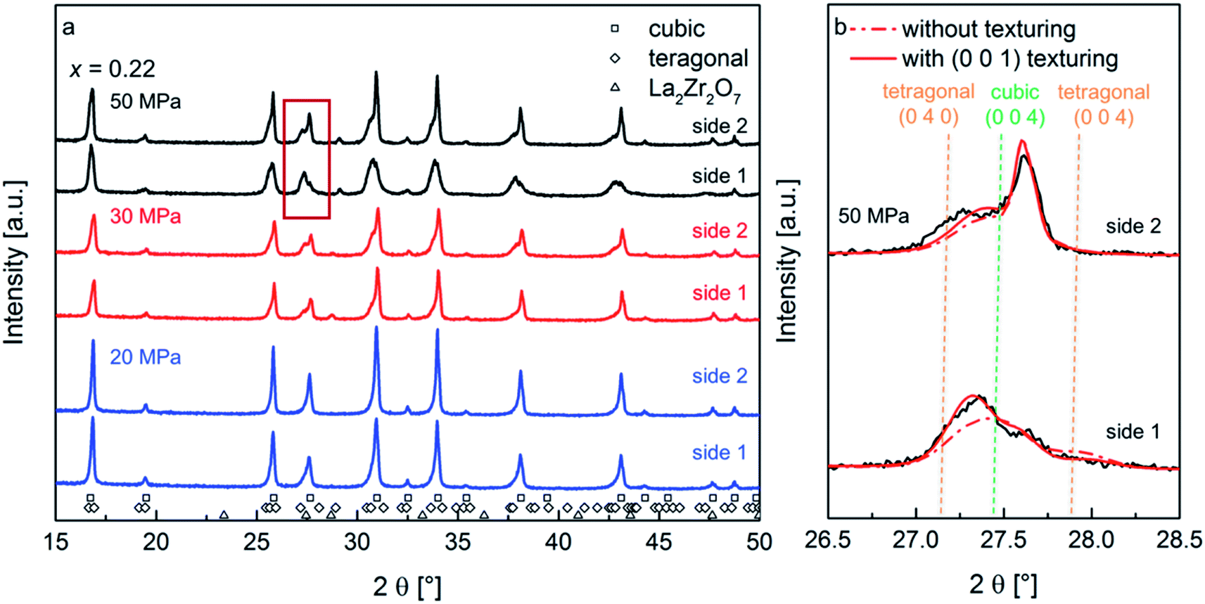 | ||
| Fig. 1 X-ray diffraction of the Li7−3xLa3Zr2AlxO12 with x = 0.22 ceramics sintered at 950 °C at various pressures, measured on both sides of the pellets (side 1 and side 2) (a); magnified region inside the red frame of the XRD pattern in (a) showing the experimental data (black solid line) and Rietveld refinement fits with (red solid line) and without (red dashed line) the application of the March-Dollase model for the (0 0 1) preferred orientation of the tetragonal phase. The best fit with the experimental data is obtained for the model with (0 0 1) texture: its Rwp value decreases to 9.7% in contrast to an Rwp value of 11.2% without the preferred orientation model (b). | ||
The diffraction pattern of the pellet surfaces of the sintered ceramics, measured on both sides of the pellet, are shown in Fig. 1a. At increased pressures, the formation of small amounts of a pyrochlore type phase is observed, however, the overall amount of this phase remains small (at maximum 2 wt%). This leads to the assumption that the formation of the La2Zr2O7 phase is a result of smaller differences of Li contents on each side of the pellet due to electromigration of Li-ions on account of the direct current electric field applied during sintering.18,19 However, since the functional properties of the ceramics do not depend strongly on this phase and due to the fact that its fraction is small, it can be neglected as discussed below.
At the lowest pressure of 20 MPa, a small asymmetry of the XRD reflections appears. This asymmetry becomes more pronounced with increasing pressure. The development of a fit model, which serves to estimate the microstructural changes via Rietveld analysis of the recorded XRD patterns, was attempted by limiting the amount of refined parameters. The justification of this model for the sample prepared at the highest pressure is presented in the following.
At first, it appears plausible to assign this line profile asymmetry to a non-symmetric distribution of cubic lattice parameters of garnet phases, and this model was tested for initial refinements. It was found that the degree of asymmetry strongly depends on the Miller indices of reflections, e.g., (0 0 l) reflections show a stronger degree of asymmetry. However, no reasonable fit of the reflection profile and their intensities was obtained using this model. Investigation of the XRD pattern of side 1 for the ceramic prepared at 50 MPa suggests the suitability of a model consisting of a cubic (Iad) and a distorted tetragonal (I4/amd) garnet type phase (the latter with an increased unit cell volume) as a better starting point for obtaining a more reasonable fit of the experimental pattern. Using this model for all prepared samples, an increase of the tetragonal distortion is obtained with increasing pressure (see Table 1). Additionally, the reflections of the tetragonal phase show an increased microstrain broadening as compared to the cubic phase.
| Sample pressure | Phase | Phase fraction [wt%] | Unit cell volume [Å3] | Microstrain | c/a |
|---|---|---|---|---|---|
| 50 MPa | Cubic garnet | 40.6(1) | 2176.9(5) | 0.124(2) | 1 |
| Tetragonal g. | 57.3(1) | 2200.3(6) | 0.330(2) | 0.983 | |
| La2Zr2O7 | 2.11(1) | 1205.7(8) | — | 1 | |
| 30 MPa | Cubic garnet | 58.2(1) | 2177.7(2) | 0.045(1) | 1 |
| Tetragonal g. | 40.5(1) | 2214.3(2) | 0.313(1) | 0.989 | |
| La2Zr2O7 | 1.35(1) | 1261.8(4) | — | 1 | |
| 20 MPa | Cubic garnet | 45.5(1) | 2177.1(1) | 0.043(2) | 1 |
| Tetragonal g. | 54.5(1) | 2191.7(10) | 0.204(9) | 0.994 |
Tetragonal garnet phases are known to be found for lithium rich compositions (x ∼ 0) in the system Li7−3xLa3Zr2AlxO12.20,21 A redistribution of Li and Al ions upon sintering can be ruled out as the origin for the appearance of the distorted tetragonal phase, since the tetragonal phase should remain present after grinding the pellet to a powder. Furthermore, the tetragonal garnet phase is known for a reduced conductivity by two orders of magnitude compared to the cubic modification, which was not observed in the impedance study reported in Section 2.3. Therefore, the formation of the tetragonal phase can be traced back to microstructural effects occurring during the FAST process and is considered as a distortion of the cubic unit cell. According to the XRD structure analysis, with decreasing pressure, the microstrain of the tetragonal phase decreases from 0.330, through 0.313 down to 0.204, while the c/a ratio increases approaching unity (i.e., showing pseudo-cubic symmetry). This observation clearly links the observed tetragonal distortion to the applied pressure during FAST treatment.
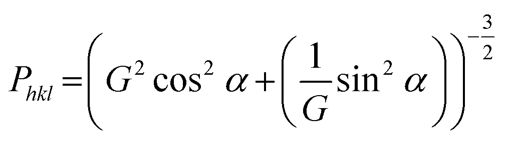
Although the two-phase model of a tetragonal and a cubic garnet phase served well for obtaining an improved description of the reflection profiles, misfits could still be observed between the simulated and experimental intensity distribution within a reflection group. It was found that (h 0 0) reflections appeared to have an increased intensity as compared to (0 0 l) reflections. This observation indicates that the tetragonal distortion might be accompanied by a texturing effect occurring during the FAST treatment. Therefore, a preferred orientation model according to March-Dollase was applied for the distorted tetragonal phase.22 This model requires the predefinition of a direction to which the texturing occurs. Different choices of this direction were tested, among which the (0 0 1) preferred orientation was found to result in an improved fit quality (Rwp value of 9.7% in contrast to an Rwp value of 11.2% without the preferred orientation model). The March-Dollase model only includes a single additional refinement parameter, G, used for the calculation of the preferred orientation function Phkl, which is the correction factor applied to the calculated intensity of each reflection (h k l) to account for their intensity changes in the experimental XRD pattern due to preferred orientation. The Phkl dependence is given below, with α being the angle of intersection between the lattice plane of reflection (h k l) and the predefined texturing lattice plane, (0 0 1):
 | (1) |
The best fit of the experimental with the Rietveld refined pattern calculated using a distorted tetragonal phase with (0 0 1) preferred orientation, result in G values of 1.35, 1.45 and 1.39 for the samples sintered at 50 MPa, 30 MPa and 20 MPa, respectively, which are found to be slightly different for the different pellet sides (ΔG = 0.01 to 0.09 for increasing pressure). This phenomenon can be explained by the experimental setup during field assisted sintering, where the upper piston is moved uniaxially compressing the specimen, while the lower piston is fixed. The best-fit value of G = 1.35 for the sample sintered at 50 MPa leads to intensity correction functions Phkl of 0.36 for the (0 0 4)-reflection (i.e. decrease in intensity in comparison to a randomly oriented sample) and 1.66 for the (0 4 0)-reflection (i.e. increase in intensity in comparison to a randomly oriented sample), respectively, for the distorted tetragonal garnet structure with a (0 0 1) preferred orientation. The X-ray diffraction data and the Rietveld refinement with and without considering the preferred orientation model are shown in Fig. 1b for both sides of the ceramic sintered under 50 MPa. It is also remarkable that no texturing of the cubic phase fraction was observed.
The texturing model implies that, in comparison with a statistical distribution of crystallite orientations, less crystallites of the tetragonal phase show (0 0 1) lattice planes with reduced lattice plane distance oriented parallel to the pellet surface, while more crystallites with (1 0 0) and (0 1 0) lattice planes parallel to the pellet surface, i.e., the set of lattice planes with increased lattice plane distances, are found more often. Therefore, most crystallites are oriented with the larger lattice parameters a = b(>c) of the tetragonal phase, which correspond to the (1 0 0) and (0 1 0) inter-planar distances, perpendicular to the pellet surface, i.e., parallel to the applied force during field assisted sintering. A detailed model for the formation of the tetragonal phase will be proposed in Section 2.3, combining the results from diffraction, microscopy and conductivity studies to an overall picture.
2.2. Microstructure and chemical composition
To achieve a higher accuracy for the density measurements than that obtained by the geometrical density measurements, where the open porosity and surface roughness lead to an underestimation of the pellet density, a novel method is applied using laser confocal microscopy. A detailed description of the method is reported elsewhere.23 For the samples sintered at 50 MPa, 30 MPa and 20 MPa the densities are calculated to 5.35(5) g cm−3, 5.07(5) g cm−3 and 5.11(5) g cm−3, respectively. These values lie within the range of 95% and 100% of the theoretical density (TD). Scanning electron microscopy (SEM) was carried out on cross sections of all three pellets sintered at different pressures. The corresponding micrographs are presented in Fig. S1.† The average grain size of the ceramics calculated as the mean value of 100 different grains are in the order of 2.2–2.4 μm (with minimum and maximum grain sizes of approximately 0.4 and 5.5 μm, respectively), and do not show significant differences for different pressures during FAST treatment. Additionally, all samples exhibit two visually distinguishable morphological fractions: one fraction appears as smooth, large grains of the material, while the other fraction appears in the form of much smaller particles at the grain boundaries, i.e. on the surface of the grains in cross section SEM images. The second fraction is therefore most probably a result of a liquid phase formed during sintering at 950 °C.A more detailed characterization of the microstructure, especially of the inter- and intragranular elemental distribution and actual composition, was carried out using high-angle annular dark field (HAADF) scanning transmission electron microscopy (STEM). Thin lamellae (50 nm) of the ceramics are prepared using a Ga focused ion beam instrument (FIB). Microstructural instability was observed during the FIB preparation especially around pores, which is most probably due to the decomposition of residual Li containing species like, e.g., Li2CO3, known to be beam sensitive.24 The phenomenon increases with reduced thickness of the specimen, since it becomes more vulnerable to the electron beam as well as the ion beam during final polishing of the lamellae. Nevertheless, the grains and the grain boundaries without any large pores, where the beam sensitive species presumably reside, remain stable during FIB preparation. The lamellae were transferred to the transmission electron microscope for further characterization with only a few minutes of exposure to air. Regarding the energy-dispersive X-ray spectroscopy (EDXS) analysis, we point out that Li cannot be detected. However, its presence is proved by the structure analysis of XRD patterns, which shows the formation of Li7−3xLa3Zr2AlxO12. In a previous study it was shown using 27Al magic-angle spinning nuclear magnetic resonance (MAS NMR) that Al3+ resides on a tetrahedrally coordinated site, thereby most probably replacing 3 Li+.25 On that basis the atom concentration of Li cLi, is assessed using the atom concentration of Al (x = cAl) determined by the quantification of the EDXS spectrum of the investigated sample as equal to cLi = 7 − 3cAL. Accordingly, the real chemical compositions of samples given bellow are determined by using the atom concentrations of La, Zr, Al and O obtained after the quantification of their EDXS spectra, and the assessed atom concentration of Li. The EDXS elemental maps for Zr (Kα1-line), La (Lα1-line), Al (Kα1-line), O (K-line) and C (K-line) are shown in Fig. 2.
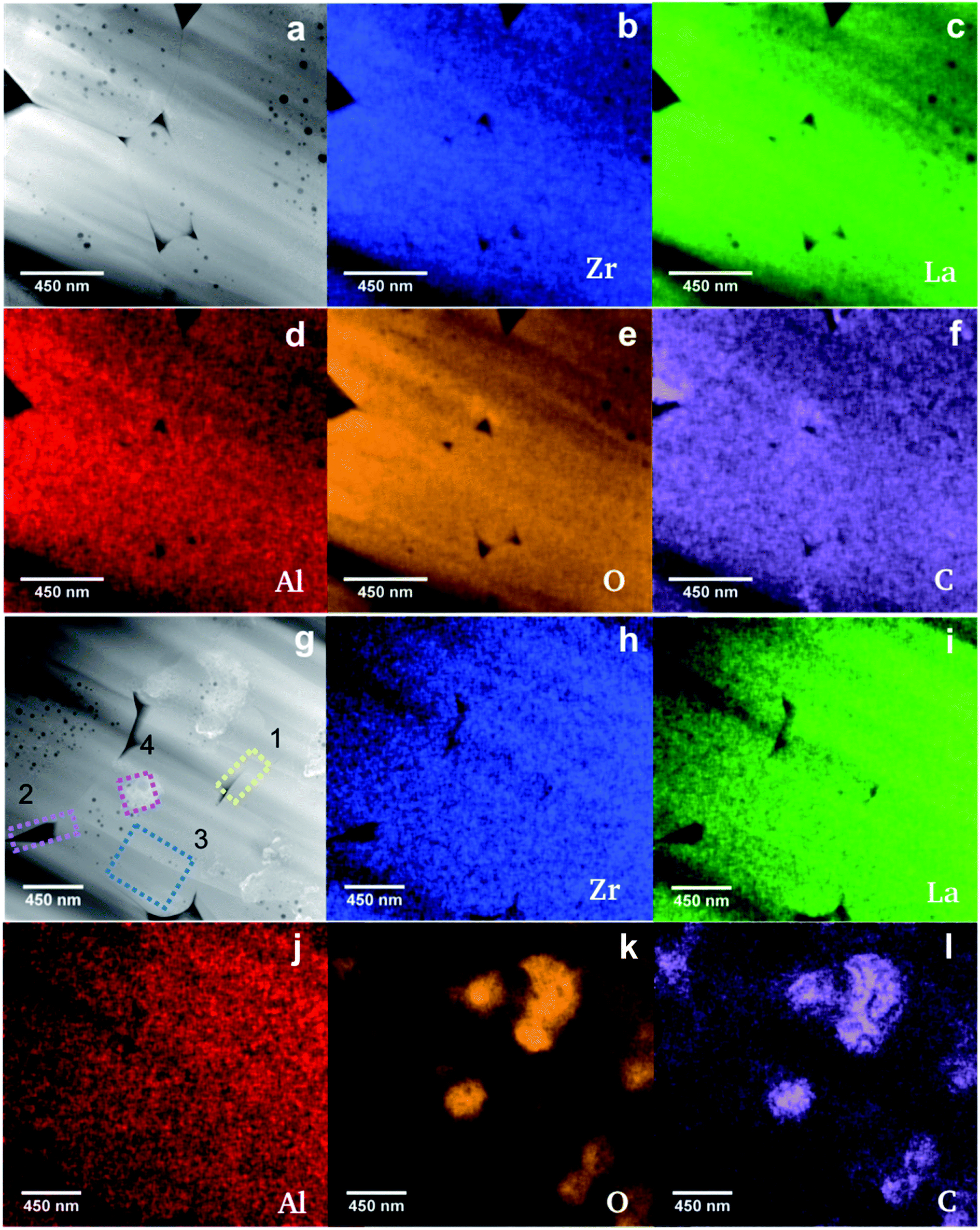 | ||
| Fig. 2 HAADF-STEM/EDXS investigation of the sintered Li7−3xLa3Zr2AlxO12 ceramic (x = 0.22): (a–f): HAADF STEM image (a) and corresponding EDXS elemental maps of Zr-Kα1 (b), La-Lα1 (c), Al-Kα1 (d), O-Kα (e) and C-Kα (f) of grains without segregation of the secondary phase (see text); (g–l): HAADF STEM image showing grains with segregation of the secondary phase with the regions used for the EDXS analysis (colored frames and labels) (g) and corresponding EDXS elemental maps of Zr-Kα1 (h), La-Lα1 (i), Al-Kα1 (j), O-Kα (k) and C-Kα (l). | ||
The EDXS elemental map of the Al distribution within the sample (Fig. 2d) clearly shows its homogeneous distribution within the Li7−3xLa3Zr2AlxO12 grains and no segregation along the grain boundaries, confirming the absence of compositional fluctuations induced during FAST treatment. EDXS elemental mapping also shows a uniform distribution of Zr and La (Fig. 2b and c), as well as, a small C contamination within the grains (Fig. 2f), with a low contamination level of up to 2 at% according to EDXS quantitative analysis, which will be neglected in the following. Additionally, the HAADF STEM image shows the formation of circular pores within some grains. EDXS indicated no segregation of Al, as well as, of any other element in regions where the observed pores reside (Fig. 2b–f). It can be ruled out that the pores are an artefact due to sample preparation for imaging, since other samples with different powder processing history do not exhibit intergranular pores. The agglomerated calcined powder with sintering necks between the particles, which was used for FAST processing, might be the origin for the pore formation. The quantitative EDXS analysis shows the formation of stoichiometric Li6.1±0.3La3.0±0.3Zr2.0±0.2Al0.3±0.1O12.0±0.6 with the Li-content being calculated from the measured Al-content within the intragranular regions with and without pores assuming the nominal composition Li7−3xLa3Zr2AlxO12. This is in good agreement with the expected composition considering the margin of error. Additionally, grain boundary regions have a chemical composition of Li6.1±0.3La3.3±0.3Zr2.0±0.2Al0.3±0.1O13.3±0.9, which agrees with the composition of grain regions. The HAADF STEM image presented in Fig. 2g shows the precipitation of a secondary phase with brighter contrast compared to that of the grains. Many regions are chosen for the quantification of the EDXS maps of the ceramic, which are shown in Fig. 2g and the results are given in Table 2. A significantly sub-stoichiometric oxygen composition of grains containing precipitates is noted in comparison to grains without a secondary phase. The uniform distribution of La, Zr and Al (corresponding EDXS maps in Fig. 2h–j) suggests that the secondary phase does not contain any of these elements. After subtraction the chemical composition of the pure grain (region 3 composition in Table 2) from the mixed composition of the grain and the segregated material (region 4 composition in Table 2), a chemical composition of CO2.9 is calculated for the secondary phase. This corresponds to the composition expected for Li2CO3 taking into account that Li cannot be detected. The oxygen deficiency of the garnet phase around the segregated material as well as the confirmation that the segregation is a carbonate containing phase, leads to the conclusion that oxygen as well as Li are extracted from the garnet structure during sintering and react with carbon contamination most probably from adsorbed CO2 during the short transport of the powder in air. EDXS maps are further used to determine the chemical composition of regions at the grain boundaries (yellow and magenta frames labeled by 1 and 2 in Fig. 2g and Table 2). The quantification results are comparable, considering the margin of error, with the sub-stoichiometric oxygen composition for the grains containing a secondary phase. Further, the sub-stoichiometric oxygen content of the grain boundaries might indicate the formation of Li2CO3 in the corresponding regions during sintering, which cannot be detected using HAADF STEM/EDXS due to its decomposition during field assisted sintering or FIB processing. Moreover, the oxygen deficient composition may play a crucial role in the stability of Al-doped LLZO against Li metal.26 The Al-content is between x = 0.20 and x = 0.30 throughout all measurements, which is in good agreement with the nominal Al content of x = 0.22.
| Region | La [mol] | Zr [mol] | Al [mol] | O [mol] | C [mol] |
|---|---|---|---|---|---|
| 1 | 3.1(3) | 2.0(2) | 0.2(1) | 10.6(9) | 0.2(1) |
| 2 | 3.2(3) | 2.0(2) | 0.3(1) | 9.1(8) | 0.2(1) |
| 3 | 3.1(3) | 2.0(2) | 0.2(1) | 7.6(3) | 0.2(1) |
| 4 | 3.2(4) | 2.0(4) | 0.2(1) | 21.6(9) | 5.2(2) |
2.3. Li-ion conductivity
AC-impedance spectroscopy is carried out between 220 K and 298 K to determine the Li-ion conductivity of the sintered ceramic. Fig. 3 shows the Nyquist plots for the low temperature measurements with arrows indicating the frequencies at the maximum of the semi-circles at 220 K. Utilizing low temperatures allows for the detection of the bulk and grain boundary contribution to the spectrum. The decreased microstrain due to the application of different pressures during sintering is correlated with an increase in both bulk and grain boundary resistances.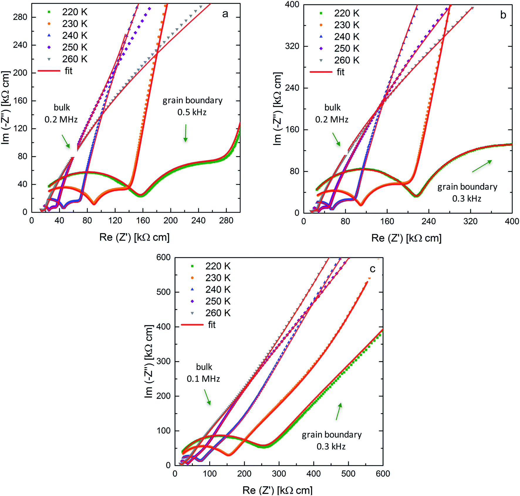 | ||
| Fig. 3 Nyquist plots and corresponding fits for Li7−3xLa3Zr2AlxO12 samples (x = 0.22) with blocking Au electrodes at 220 K up to 260 K sintered at pressures of 50 MPa (a), 30 MPa (b) and 20 MPa (c). | ||
The Arrhenius plots for all three ceramics sintered at 50 MPa, 30 MPa and 20 MPa are shown in Fig. 4a, the bulk and grain boundary contributions to the conductivity are plotted separately in Fig. 4b and c. The total room temperature ionic conductivities are 0.42 mS cm−1 for the sample sintered under the highest pressure of 50 MPa, decreasing to 0.36 mS cm−1 at 30 MPa and to 0.26 mS cm−1 at the lowest pressure of 20 MPa. A similar trend is observed for the activation energies determined from the Arrhenius plots: the activation energy of 0.37 eV for the sample sintered at 50 MPa is lowest and increases for the samples sintered at 30 MPa and 20 MPa to 0.38 eV and 0.41 eV, respectively.
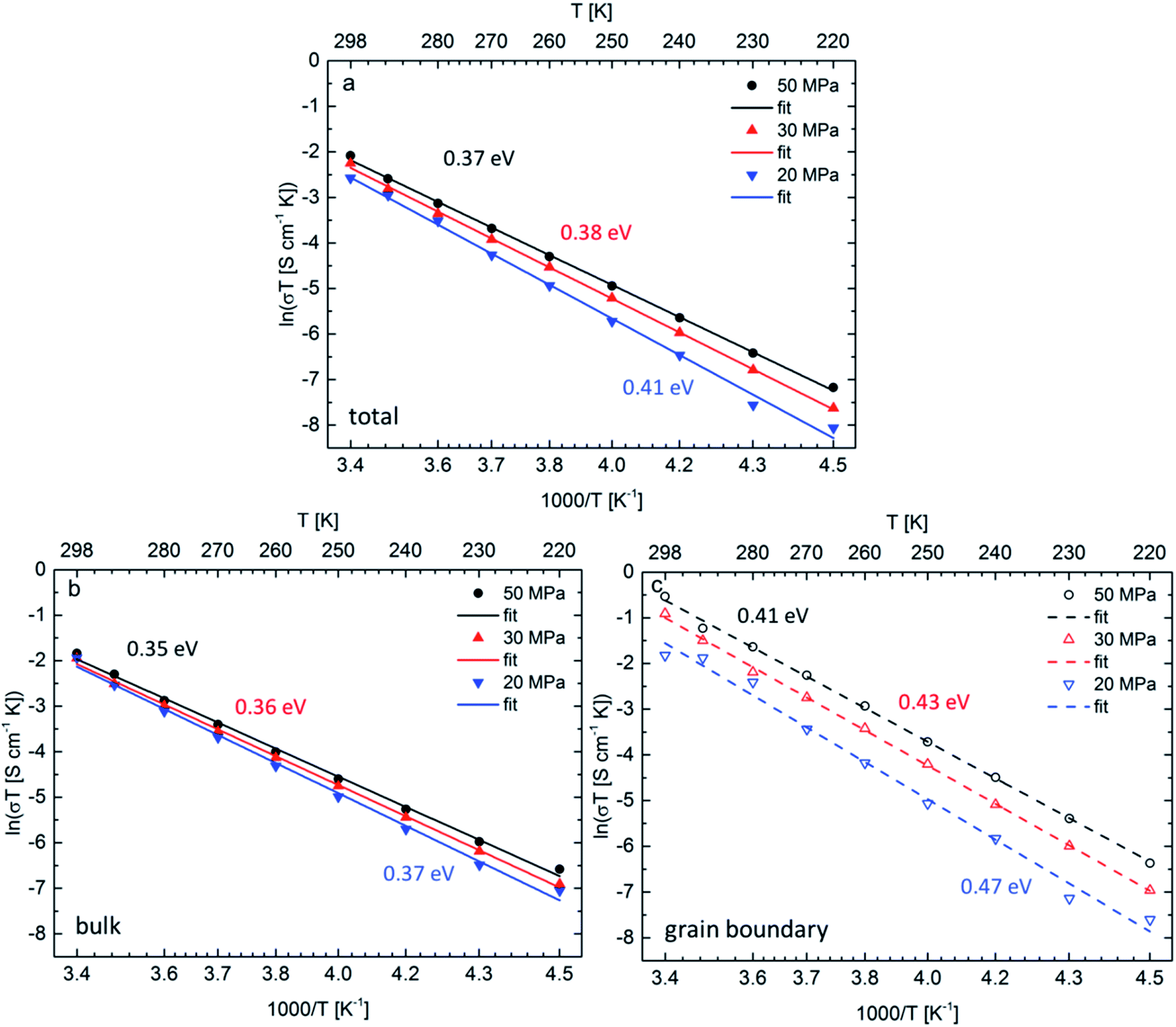 | ||
| Fig. 4 Arrhenius plots of the total Li-ion conductivity (a), bulk conductivity (b) and grain boundary conductivity (c) between 220 K and 298 K for three different ceramic densities achieved by different pressures. | ||
Although both, activation energy and resistance for grain and grain boundary processes decrease on increasing pressure, the grain boundary contribution is more significant.11 A change of 5% in density could not be expected to have such drastic influence on the activation energy for Li-ion diffusion in Li7−3xLa3Zr2AlxO12, therefore, it is assumed that the change in activation energy is attributed to the change of microstrain and the formation of the strain-induced textured distorted tetragonal phase, which also correlates well with the applied pressure during sintering. The increased tetragonal distortion, which is quantified by a decreased c/a ratio and increasing microstrain (see Section 2.1), is accompanied by an increase in conductivity. Therefore, it appears that the symmetry reduction cannot be induced by an ordering of lithium ions and vacancies, which is known to result in a strong inhibition of the lithium diffusion within garnet materials. To understand this finding, the following model is proposed for the sintering process (see Fig. 5): (1) the grain boundary conductivity is strongly affected compared to the bulk conductivity. This phenomenon can be explained by the liquid phase sintering mechanism taking place during field assisted sintering. An overall small amount of liquid phase, Li2CO3, might form at the particle interconnections during heating period at an initial pressure of only 15 MPa. (2) As soon as the sintering temperature is reached the pressure is increased to the respective value and held during the complete dwell time (3 min). During this time the grains rearrange and unite at the grain boundaries under the force of the uniaxial pressure under elimination of the pore volume. (3) After completion of the sintering process the uniaxial pressure is released before cooling of the specimen. This pressure release is non-isotropic; while expansion perpendicular to the pellet surfaces is facilitated, radial expansion within the circular plane of the pellet cannot occur due the restrictions of the die walls. (4) Certain cubic grains, i.e., grains with unit cell faces aligned parallel to the pellet surface, possess a matching orientation in relation to this non-isotropic force field, and can adopt to it by inducing a tetragonal distortion with expansion perpendicular to and contraction within the pellet surface. Since the Li-ion diffusion mechanism in the garnet structure is a vacancy hopping mechanism27 increased space along the diffusion direction of the lithium ions could be beneficial for ionic transport.21 (5) It can also be expected that the force field is different within one crystallite, and increases towards the grain boundary region. Therefore, a considerable part of a crystallite can reside in a less strained state, i.e., the cubic phase fraction found after sintering. The liquid phase residing at the grain boundaries at this point would play a significant role in accelerating this proposed process for crystallites near the grain boundaries due to enhanced diffusion processes compared to the solid bulk of the ceramic specimen.
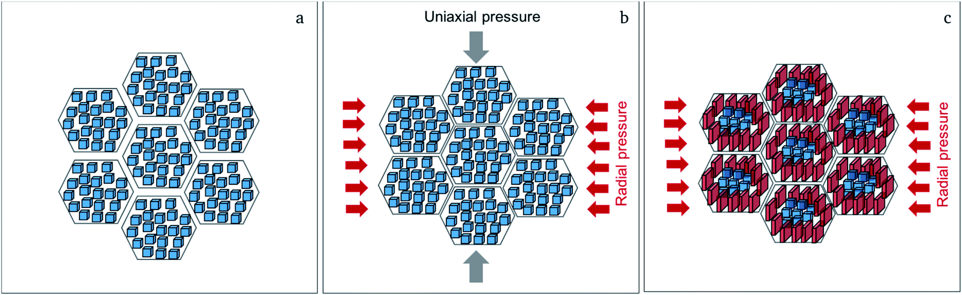 | ||
| Fig. 5 Proposed mechanism for the formation of the textured distorted tetragonal phase showing the cubic starting powder (a); the sintering process at 950 °C at uniaxial pressure, where radial volume expansion takes place (b); the formation of the textured distorted tetragonal phase near the grain boundary regions (red crystallites) after release of the uniaxial pressure during cooling of the sample due to residual radial pressure (c). | ||
2.4. Cycling and area specific resistance of symmetrical cells
The cycling behavior of two samples sintered under 50 MPa and 30 MPa is determined by attaching Li-electrodes on both sides of the pellet, as previously reported.10 Two different current densities are used, 50 μA cm−2 and 75 μA cm−2. Previous experiments show stability up to 50 μA cm−2, therefore, the influence of a higher current density is studied. Galvanostatic cycling is shown in Fig. 6 for samples exhibiting a different microstrain. Stable cycling was found for both samples for at least 100 hours (corresponding to 25 cycles). For identical currents, the ceramics with higher conductivity prepared at higher pressures require lower cycling potentials. The increase of cycling potentials with higher cycle numbers is more pronounced for ceramics prepared at lower sintering pressures, which might be related to larger losses during charge transfer presumably at the interface between LLZO and the Li-electrodes. The main difference between the ceramics sintered at 50 and 30 MPa is the transport behavior at the grain boundary probably due to altered microstrain, which seems to be the determining factor regarding the potential increase during cycling.28 For the ceramic sintered at 50 MPa (highest microstrain) the potentials are symmetric with respect to the current direction, whereas an increased asymmetry is found starting from the 8th cycle for the ceramic prepared at lower pressure. This might be an indication that the losses are related to the interfaces on each side of the solid electrolyte.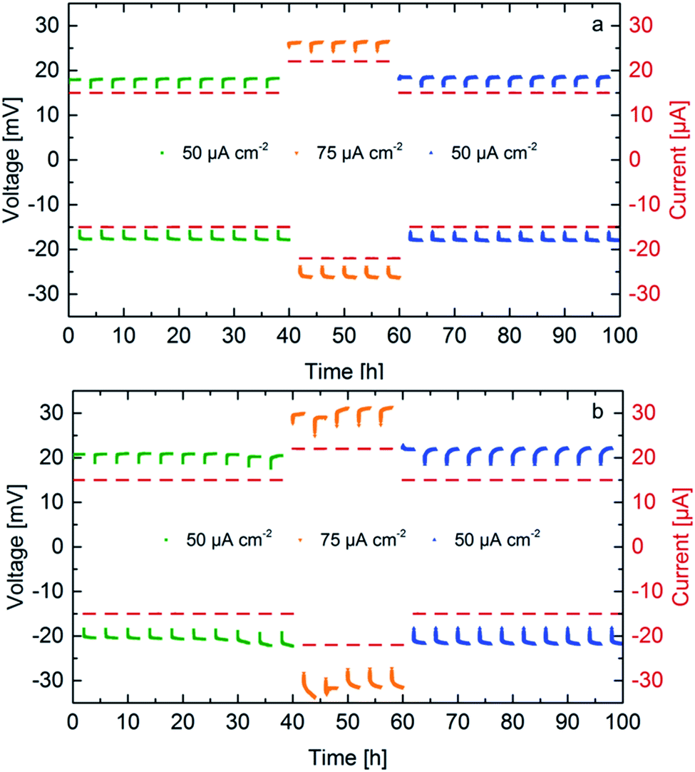 | ||
| Fig. 6 Galvanostatic cycling of symmetrical cells Li|LLZO|Li at different current densities for Li7−3xLa3Zr2AlxO12 samples with x = 0.22, sintered at 50 MPa (a) and 30 MPa (b). | ||
AC-impedance spectroscopy is conducted to determine the area specific resistance (ASR) for the samples sintered at a pressure of 50 MPa and 30 MPa at 298 K. Fig. 7 shows the Nyquist plots for the measurements with blocking Au-electrodes in comparison to non-blocking Li-electrodes before cycling and after cycling for 10 cycles at 50 μA cm−2, 5 further cycles at 75 μA cm−2 and additional 10 cycles at the initial current density. The arrows indicate the frequency at the maximum of the grain boundary semi-circle, clearly identifiable in both spectra with blocking and non-blocking electrodes. The fit of the sample with non-blocking electrodes uses an R(R CPE)(R CPE) (CPE: constant phase element, R: resistance) equivalent circuit, while the resistance of the first (R CPE) circuit is fixed to the value of the grain boundary resistance obtained with blocking Au electrodes. As previously reported the spectra with non-blocking Li electrodes are shifted to higher resistances compared to the ones with blocking Au electrodes, due to a reduced corrected electrode surface area.10 The shift is calculated to Δ = 70.2 Ω for the ceramic sintered at 50 MPa and to Δ = 42.7 Ω for the ceramic sintered at 30 MPa. This leads to a corrected surface area Ac, which is 90% and 94% of the theoretical surface area At for ceramics sintered at 50 MPa and 30 MPa, respectively. An overview on the calculated ASR values is shown in Table 3. The corrected values due to the surface area deviation are placed in parenthesis. The ASR for the sample sintered at 50 MPa is calculated to 41.2 Ω cm2 (37.1 Ω cm2), while the sample sintered at 30 MPa shows a slightly higher ASR of 44.3 Ω cm2 (41.6 Ω cm2). After the first 10 cycles the ASR of the sample sintered at a higher pressure remains stable, while it increases for the sample sintered at a lower pressure. This is an indication of a higher instability of the interface between the solid electrolyte showing a lower microstrain and Li electrode, which can be explained by the higher resistance and activation energy of the grain boundary region. Cycling for only 5 cycles at a higher current density leads to an increase of the ASR with similar proportion for both cells, while 10 further cycles at the initial current density shows stable behavior. The ASR after 25 cycles calculates to 46.5 Ω cm2 (41.9 Ω cm2) and 51.9 Ω cm2 (48.8 Ω cm2) for the sample sintered at 50 MPa and 30 MPa, respectively. These ASR values are amongst the best values reported to date for the interfacial resistance between LLZO and Li metal.1,11,12,29
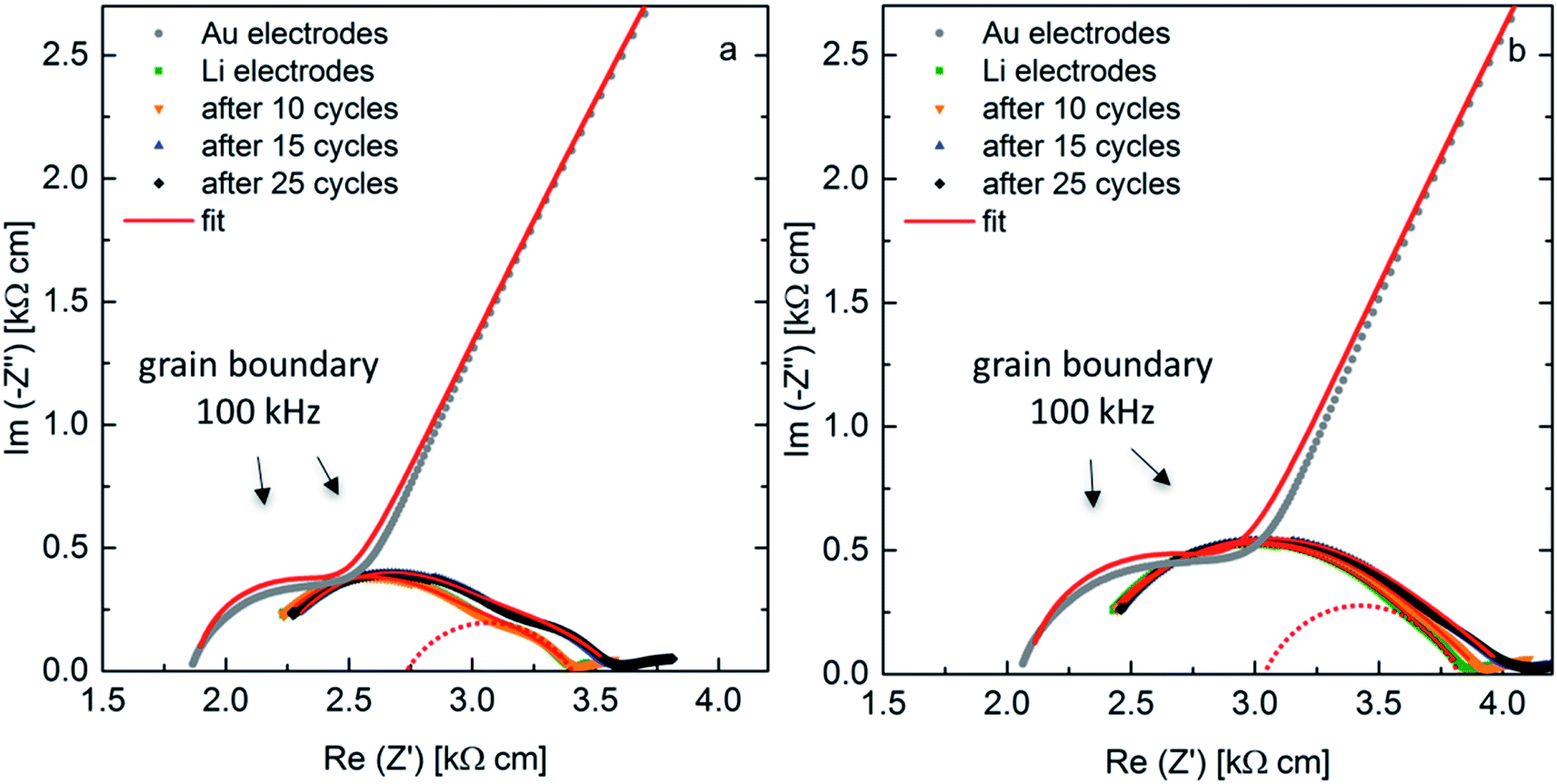 | ||
| Fig. 7 AC-impedance spectra at 298 K with blocking Au-electrodes and non-blocking Li-electrodes as-prepared and after cycling for samples with x = 0.22, sintered at 50 MPa (a) and 30 MPa (b). | ||
| Sample pressure | ASR [Ω cm2] | |||
|---|---|---|---|---|
| As prepared | After 10 cycles | After 15 cycles | After 25 cycles | |
| 50 MPa | 41.2 (37.1) | 41.5 (37.3) | 46.3 (41.7) | 46.5 (41.9) |
| 30 MPa | 44.3 (41.6) | 45.8 (43.1) | 51.5 (48.4) | 51.9 (48.8) |
3. Cycling of a full hybrid cell
A promising approach for cell assembly is introduced in this work to exploit the advantages of the solid electrolyte, especially the application of Li metal as an anode, while maintaining a good contact to the conventionally used slurry-based LiCoO2 (LCO) cathode (see schematic in Fig. 8). Liquid electrolyte (1 M LiPF6 based solution) is used in the cathode to provide easy transport of the Li-ions to the interface with the solid electrolyte. Cyclic voltammetry is performed at room temperature between 3.2 V and 4.2 V vs. Li/Li+ at a rate of 0.05 mV s−1. The resulting voltammograms are shown in Fig. 8a. Three oxidation peaks are expected for the LiCoO2 cathode at 3.9 V, 4.1 V and 4.2 V. The first peak corresponds to the two-hexagonal phase region, while the next two peaks are attributed to a phase transition between the ordered and disordered Li-ion arrangement in the CoO2 framework occurring around a composition Li0.5CoO2.30 The oxidation peaks for this cell are not clearly separated and show a maximum current at 4.05 V, which is shifted to a 100 mV higher potential compared to the expected potential. The reduction peaks on the other hand are observed clearly in the first cycle, confirming reversible cycling with an overpotential of approximately 200 mV. The hybrid cell shows a good 3.6 V-plateau efficiency, which is stable throughout all five cycles. The high maximum current achieved in the first cycle decreases starting the second cycle and a more pronounced continuous fading of the current is observed with further cycling. It is evident that the kinetics in the cell containing a solid electrolyte are slow. Therefore, slower cycling rates and a higher cutoff potential might allow for more accurate detection of the occurring redox reactions. Additionally, an optimization of the electrolyte thickness would reduce the overpotential and enhance cell performance. Nevertheless, successful cycling was achieved combining FAST prepared LLZO ceramics and the liquid electrolyte containing cathode composite in this configuration for the first time.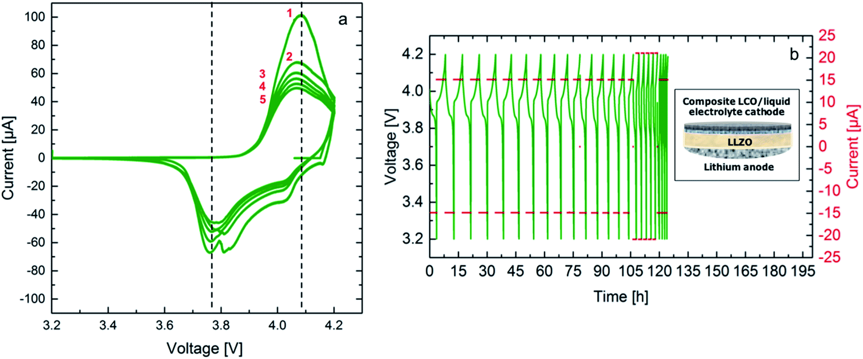 | ||
| Fig. 8 Cyclic voltammograms of the hybrid cell LCO|LiPF6|LLZO|Li performed at a scan rate of 0.05 mV s−1 at 25 °C for 5 cycles in the potential range between 3.2 V and 4.2 V vs. Li/Li+, black dashed lines serve as guide to the reader for the overpotential (a) galvanostatic cycling at 15 μA (C/5) and 21 μA (C/4) in the potential range between 3.2 V and 4.2 V vs. Li/Li+ at 25 °C, inlay shows a schematic of the hybrid cell (b). | ||
As it is shown in Fig. 8b galvanostatic cycling is performed at room temperature for both cells using two currents, 15 μA and 21 μA, which correspond to a C/5 and a C/4 rate, respectively. The calculation considers the theoretical capacity expected for the voltage range from 3.2 V to 4.2 V vs. Li/Li+ and the mass of the active material, LCO, leading to a theoretical discharge capacity of 100 mA h g−1. These currents were chosen according to the previous experiments for symmetrical cells with Li electrodes, where cycling is expected to be stable. The first 15 cycles at the lower current show stable cycling. Stable cycling is observed after increasing the current for further 5 cycles. The hybrid cell could not be cycled at the initial current. In total it was cycled for 20 cycles corresponding to a duration of 120 hours. It has to be noted at this point that the Li anode of the hybrid cell has been previously cycled in a symmetrical cell configuration, therefore, the failure of the cell after application of a higher current is most probably related to the degradation at the solid electrolyte–anode interface. Furthermore, the first discharge cycle of the galvanostatic cycling shows an internal resistance drop (IR drop) of 10 mV for the hybrid cell. The voltage drop corresponds to a resistance of 666 Ω, which is in the same range of the total resistance of the solid electrolyte. This resistance could be lowered further by reducing the thickness of the solid electrolyte. Additionally, the discharge capacity for the first cycle from 4.2 V down to 3.2 V vs. Li/Li+ are calculated to be 84 mA h g−1. This high value indicates that the hybrid cell allows for the discharge of a large amount of the active material on the cathode side. This might be related to the high surface roughness of the solid electrolyte and the uniform pressure applied when using a ceramic electrolyte. The calculated Li amount cycled in two hours is 8.67 × 10⁻⁷ mol. The discharge capacity continues fading reaching 97% during the second discharge.
Although further improvements of the bulk hybrid cell are required, the results shown here confirm that such cell design offers the possibility for reversible cycling. Additionally, it is shown that a charge transfer between LiPF6 based liquid electrolyte and LLZO ceramic electrolyte is possible, paving the way to a Li-ion battery, which overcomes current safety issues of liquid electrolytes, while maintaining their advantages within the active electrode composite.
4. Conclusion
This work shows the correlation between induced microstrain and the applied pressure during FAST, with beneficial impact on the overall conductivity of garnet based ceramic solid electrolytes. This study emphasizes the possibility to use microstrain as an additional parameter for the improvement of the electrochemical performance of garnet type solid electrolytes for all-solid-state batteries. The proposed microstrain mechanism is in agreement with various independent measurements, ranging from powder diffraction via microscopy studies to electrochemical considerations. The solid electrolyte shows a high ionic conductivity, and the surface morphology results in low ASR towards Li metal, which are amongst the best values reported in the literature. The formation of the distorted tetragonal phase with increased microstrain as well as the decreased c/a ratio with increasing pressure during the sintering process was correlated with enhanced ionic conductivity and smaller activation energy. The enhanced performance is mainly in the grain boundary region, where the distorted tetragonal phase presumably resides. Additionally, a hybrid cell approach was introduced, which can be used to eliminate the solid–solid interface between the solid electrolyte and the slurry-based conventional LCO cathode via the addition of a small amount of liquid electrolyte. The liquid electrolyte ensured good charge transfer between the microscopically rough surface of the solid electrolyte and the cathode, while it is completely separated from the Li anode. With respect to the cycling performance, the hybrid cell showed high discharge capacity and good 3.6 V-plateau efficiency. Long time measurements are necessary to determine the degradation processes along the electrolyte–anode interface. Nevertheless, the practical approach of introducing a liquid electrolyte only on the cathode side confirms that the fabrication of a hybrid cell is a promising alternative to existing cell designs.5. Experimental section
5.1. Ceramic preparation and cell assembly
The Li7−3xLa3Zr2AlxO12 (x = 0.22) ceramic was prepared using a combination of nebulized spray pyrolysis (NSP) and field assisted sintering technology (FAST, Dr Sinter Lab 211-Lx).10 The detailed synthesis process is reported in previous work, where the water-based precursor solution (total cation concentration 0.05 mol l−1) was prepared by mixing the Zr precursor (Zr(C5H7O2)4, ABCR, 98%), dissolved in a small amount of methanol and the nitrate based precursors of Li (30 wt% in excess), La and Al (LiNO3, Sigma Aldrich, 99.99%, La(NO3)3·6H2O, Alfa Aesar, 99.9%, and Al(NO3)3·9H2O, Merck, 98.5%) dissolved in deionized water.31 The as-synthesized powder after NSP was calcined at 900 °C for 1 h under flowing argon atmosphere to obtain the desired cubic garnet structure. Field assisted sintering was carried out at 950 °C for 3 min under an argon atmosphere, which was introduced to the chamber at 500 °C during heating at a rate of 100 °C min−1. The cooling rate was also set to 100 °C min−1 to avoid rapid cool down, which might lead to failure of the specimen. The pressure during sintering was set to 20 MPa, 30 MPa and 50 MPa and was relieved completely before cooling was initiated. Between all preparational steps, samples were stored inside an Ar filled glovebox (H2O levels below 1 ppm) to avoid Li+/H+ exchange.32 Due to the fact that the ceramics are highly dense after the sintering process, Li+/H+ exchange can be expected to only occur at traces at the surface. The ceramics were subsequently polished manually with polishing paper with a grit size starting 800 up to 1200.Symmetrical cells with Li-electrodes were assembled using a soldering iron inside an Ar-filled glovebox as previously reported in detail.10 Copper current collectors were attached on both sides.
For the assembly of a full hybrid cell a slurry-based cathode with a mass ratio of 8![[thin space (1/6-em)]](https://www.rsc.org/images/entities/char_2009.gif) :1:1 of LiCoO2 (Sigma-Aldrich), carbon black (Sigma-Aldrich, 699624) and polyvinylidene fluoride (PVDF) (SOLEF) was prepared. A solution composed of 10 wt% of PVDF and 90 wt% of N-methyl-2-pyrrolidone (NMP) (BASF) was added to the powder mixture. An excess of NMP is added (approximately 30 wt% of the active material) reducing the viscosity of the slurry. A high-performance dispersing instrument T25 digital Ultra-Turrax (IKA) is used in subsequent intervals of 5 min at 8000 rpm, a 2 min break, followed by 10 min stirring at 8000 rpm for the preparation of the slurry. In the following 5 min break NMP is added to the slurry ensuring optimal viscosity for homogeneous stirring. The stirring intervals are then repeated, followed by addition of NMP. The process is repeated three times. The total amount of NMP added during stirring is 3 times the mass of the active material. The slurry is then printed on an Al foil using a doctor blade technique with an approximate thickness of 120 μm. The electrode is then placed in an oven set to 40 °C for approximately 24 hours during which the evaporation of NMP takes place. After the drying process, the cathode with a diameter of 6 mm is formed using a puncher and transferred to a vacuum oven inside an Ar-filled glovebox and dried at 100 °C for 12 hours.
:1:1 of LiCoO2 (Sigma-Aldrich), carbon black (Sigma-Aldrich, 699624) and polyvinylidene fluoride (PVDF) (SOLEF) was prepared. A solution composed of 10 wt% of PVDF and 90 wt% of N-methyl-2-pyrrolidone (NMP) (BASF) was added to the powder mixture. An excess of NMP is added (approximately 30 wt% of the active material) reducing the viscosity of the slurry. A high-performance dispersing instrument T25 digital Ultra-Turrax (IKA) is used in subsequent intervals of 5 min at 8000 rpm, a 2 min break, followed by 10 min stirring at 8000 rpm for the preparation of the slurry. In the following 5 min break NMP is added to the slurry ensuring optimal viscosity for homogeneous stirring. The stirring intervals are then repeated, followed by addition of NMP. The process is repeated three times. The total amount of NMP added during stirring is 3 times the mass of the active material. The slurry is then printed on an Al foil using a doctor blade technique with an approximate thickness of 120 μm. The electrode is then placed in an oven set to 40 °C for approximately 24 hours during which the evaporation of NMP takes place. After the drying process, the cathode with a diameter of 6 mm is formed using a puncher and transferred to a vacuum oven inside an Ar-filled glovebox and dried at 100 °C for 12 hours.
The cathode printed on the Al current collector is placed in a Swagelok type connection and covered with 1 M LiPF6 based liquid electrolyte (LP30, BASF). After ensuring a complete immersion of the cathode layer, excess liquid is removed. The ceramic pellet, sintered at a pressure of 50 MPa, with a Li anode and Cu current collector already attached is placed on the liquid immersed cathode and the cell is firmly sealed. The roughness of the ceramic pellet surface facing the cathode is increased using polishing paper with a grit size of 600. This step is crucial to enhance cathode adhesion and liquid electrolyte penetration of the ceramic electrolyte surface. The assembled cell is stored in a temperature cabinet for approximately 12 hours at 25 °C in order to ensure thermal and electrochemical equilibrium prior to cycling.
5.2. Phase composition and microstrain
X-ray diffraction patterns were recorded using a Bruker D8 diffractometer with Bragg–Brentano geometry equipped with an X-ray tube with Cu anode, and a Ni filter for the removal of the Kβ radiation. A VANTEC detector and a fixed divergence slit (0.3°) were used. The measurements were performed with a step size of 0.015° with a collection time of 1 s at 30 kV and 40 mA over the 2θ angular range between 10° and 120°. The phase quantifications are performed by Rietveld analysis using the program TOPAS 4.2 (Bruker AXS, Karlsruhe, Germany).33 The instrumental intensity distribution for the X-ray data is determined empirically from a fundamental parameters set, using a reference scan of LaB6 (NIST 660a). The quality of the different refinement models discussed within the article are judged based on the quality of the overall fit, expressed by the parameter Rwp.345.3. Microstructure and chemical composition
The morphology of the as-synthesized powders is studied using high-resolution scanning electron microscopy, SEM (Philips XL30 FEG). Prior to imaging all samples are coated with Au using a sputter coater (30 s, 30 mA) to prevent electrical charging. The pellets are contacted using silver paste, in addition to the carbon tape, to the sample holder. Focused ion beam (FIB Strata 400 STEM) is used to prepare and to study cross sections of the sintered samples.High angle annular dark field (HAADF) scanning transmission electron microscopy (STEM) combined with energy dispersive X-ray spectroscopy (EDXS) is used to investigate the chemical composition. The experiments are performed on an FEI Osiris ChemiSTEM microscope at 200 kV acceleration tension, which is equipped with a Bruker Quantax system (XFlash detector) for EDXS. EDXS elemental maps are recorded and used to investigate the elemental distribution within grains and along the grain boundaries. The maps are quantified with the ESPRIT software (version 1.9) from Bruker. Using ESPRIT, element concentrations are calculated on the basis of a refined Kramers' law model,35 which includes corrections for detector absorption and background subtraction. For this purpose, standardless quantification, i.e., by means of theoretical sensitivity factors is applied, without thickness correction.
5.4. Electrochemical characterization
AC-impedance spectroscopy using a frequency response analyzer (Solartron 1260) was carried out on symmetrical cells with both blocking Au electrodes that were sputtered onto the polished ceramic pellet and non-blocking Li electrodes that were melted on both sides of the pellet using the procedure previously described.10 The measurements were carried out between 1 MHz and 100 mHz in a He-filled cryostat (Janis STVP-200-XG) for cells with Au electrodes and in an airtight Swagelock-type cell for the cells with Li electrodes. The temperature of the cryostat was varied between 200 K and 298 K, after heating the samples to 393 K to eliminate residual moisture. Symmetrical cells were measured at room temperature using both AC-IS and galvanostatic cycling, which was conducted at different current densities of 50 μA cm−2 and 75 μA cm−2. AC-IS was measured after each cycling step to determine the area specific resistance (ASR).Cyclic voltammetry and galvanostatic cycling (Solartron Analytical 1470E/1455) were carried out for the hybrid cell at room temperature. The Swagelock-type cell was placed in a temperature cabinet (Memmert IPP 260).
Conflicts of interest
The authors declare no conflict of interest.Acknowledgements
The authors would like to thank the Helmholtz Association (Germany) for financial support through the Helmholtz Portfolio Project “Electrochemical Storage in Systems – Reliability and Integration”. O. Clemens acknowledges funding within CL551/3-1 by the German Research Foundation (DFG). Karlsruhe Nano Micro Facility (KNMF, Germany) and Christian Kübel are acknowledged for providing access to FIB cross-section preparation and SEM. KNMF provided access to HAADF-STEM at the Laboratory for Electron Microscopy (LEM) for which the authors are grateful. M. Botros would like to thank Ralf Riedel and his group for providing access to the lab for slurry-based cathode preparation. We acknowledge support by the KIT-Publication Fund of the Karlsruhe Institute of Technology.References
- Y. Kato, S. Hori, T. Saito, K. Suzuki, M. Hirayama, A. Mitsui, M. Yonemura, H. Iba and R. Kanno, Nat. Energy, 2016, 1, 16030 CrossRef CAS.
- B. Dunn, H. Kamath and J.-M. Tarascon, Science, 2011, 334, 928 CrossRef CAS.
- J. Vetter, P. Novák, M. R. Wagner, C. Veit, K.-C. Möller, J. O. Besenhard, M. Winter, M. Wohlfahrt-Mehrens, C. Vogler and A. Hammouche, J. Power Sources, 2005, 147, 269 CrossRef CAS.
- Z. Zhang, Y. Shao, B. Lotsch, Y.-S. Hu, H. Li, J. Janek, L. F. Nazar, C.-W. Nan, J. Maier, M. Armand and L. Chen, Energy Environ. Sci., 2018, 11, 1945 RSC.
- J. B. Goodenough and K.-S. S. Park, J. Am. Chem. Soc., 2013, 135, 1167 CrossRef CAS.
- J. Sakamoto, E. Rangasamy, H. Kim, Y. Kim and J. Wolfenstine, Nanotechnology, 2013, 24, 424005 CrossRef.
- L. Cheng, W. Chen, M. Kunz, K. Persson, N. Tamura, G. Chen and M. Doeff, ACS Appl. Mater. Interfaces, 2015, 7, 2073 CrossRef CAS.
- K. Takada, Acta Mater., 2013, 61, 759 CrossRef CAS.
- Y. Chen, E. Rangasamy, C. Liang and K. An, Chem. Mater., 2015, 150807122056005 Search PubMed.
- M. Botros, R. Djenadic, O. Clemens, M. Matthias, H. Hahn, M. Möller and H. Hahn, J. Power Sources, 2016, 309, 108 CrossRef CAS.
- H. Yamada, T. Ito, R. Hongahally Basappa, R. Bekarevich and K. Mitsuishi, J. Power Sources, 2017, 368, 97 CrossRef CAS.
- C. Wang, Q. Sun, Y. Liu, Y. Zhao, X. Li, X. Lin, M. N. Banis, M. Li, W. Li, K. R. Adair, D. Wang, J. Liang, R. Li, L. Zhang, R. Yang, S. Lu and X. Sun, Nano Energy, 2018, 48, 35 CrossRef CAS.
- Y. Li, B. Xu, H. Xu, H. Duan, X. Lü, S. Xin, W. Zhou, L. Xue, G. Fu, A. Manthiram and J. B. Goodenough, Angew. Chem., Int. Ed., 2017, 56, 753 CrossRef CAS.
- B. Xu, H. Duan, H. Liu, C. A. Wang and S. Zhong, ACS Appl. Mater. Interfaces, 2017, 9, 21077 CrossRef CAS.
- O. Guillon, J. Gonzalez-Julian, B. Dargatz, T. Kessel, G. Schierning, J. Räthel and M. Herrmann, Adv. Eng. Mater., 2014, 16, 830 CrossRef CAS.
- J. Gonzalez-Julian and O. Guillon, J. Am. Ceram. Soc., 2015, 98, 2018 CrossRef CAS.
- M. Botros, R. Djenadic, O. Clemens, M. Möller and H. Hahn, J. Power Sources, 2016, 309, 108 CrossRef CAS.
- Z. A. Munir, U. Anselmi-Tamburini and M. Ohyanagi, J. Mater. Sci., 2006, 41, 763 CrossRef CAS.
- E. Rangasamy, J. Wolfenstine and J. Sakamoto, Solid State Ionics, 2012, 206, 28 CrossRef CAS.
- C. a Geiger, E. Alekseev, B. Lazic, M. Fisch, T. Armbruster, R. Langner, M. Fechtelkord, N. Kim, T. Pettke and W. Weppner, Inorg. Chem., 2011, 50, 1089 CrossRef.
- K. Meier, T. Laino and A. Curioni, J. Phys. Chem. C, 2014, 118, 6668–6679 CrossRef CAS.
- A. March, Z. für Kristallogr. - Cryst. Mater., 1932, 81, 285 Search PubMed.
- A. Kilmametov, R. Gröger, H. Hahn, T. Schimmel and S. Walheim, Adv. Mater. Technol., 2016, 1600115 Search PubMed.
- F. Lin, I. M. Markus, M. M. Doeff and H. L. Xin, Sci. Rep., 2014, 2, 1 Search PubMed.
- R. Djenadic, M. Botros, C. Benel, O. Clemens, S. Indris, A. Choudhary, T. Bergfeldt and H. Hahn, Solid State Ionics, 2014, 263, 49 CrossRef CAS.
- Y. Zhu, J. G. Connell, S. Tepavcevic, P. Zapol, R. Garcia-Mendez, N. J. Taylor, J. Sakamoto, B. J. Ingram, L. A. Curtiss, J. W. Freeland, D. D. Fong and N. M. Markovic, Adv. Energy Mater., 2019, 1803440 CrossRef.
- P. Bottke, D. Rettenwander, W. Schmidt, G. Amthauer and M. Wilkening, Chem. Mater., 2015, 27, 6571 CrossRef CAS.
- L. Cheng, E. J. Crumlin, W. Chen, R. Qiao, H. Hou, S. Franz Lux, V. Zorba, R. Russo, R. Kostecki, Z. Liu, K. Persson, W. Yang, J. Cabana, T. Richardson, G. Chen, M. Doeff, S. F. Lux, V. Zorba, R. Russo, R. Kostecki, Z. Liu, S. Franz Lux, V. Zorba, R. Russo, R. Kostecki, Z. Liu, K. Persson, W. Yang, J. Cabana, T. Richardson, G. Chen, M. Doeff, S. F. Lux, V. Zorba, R. Russo, R. Kostecki and Z. Liu, Phys. Chem. Chem. Phys., 2014, 16, 18294 RSC.
- D. Rettenwander, G. Redhammer, F. Preishuber-Pflügl, L. Cheng, L. Miara, R. Wagner, A. Welzl, E. Suard, M. M. Doeff, M. Wilkening, J. Fleig and G. Amthauer, Chem. Mater., 2016, 28, 2384 CrossRef CAS.
- J. Reimers and J. Dahn, J. Electrochem. Soc., 1992, 139, 2091 CrossRef CAS.
- R. Djenadic, M. Botros, C. Benel, O. Clemens, S. Indris, A. Choudhary, T. Bergfeldt and H. Hahn, Solid State Ionics, 2014, 263, 49 CrossRef CAS.
- G. Larraz, A. Orera, J. Sanz, I. Sobrados, V. Diez-Gómez and M. L. Sanjuán, J. Mater. Chem. A, 2015, 3, 5683 RSC.
- H. M. Rietveld, Phys. Scr., 2014, 89, 298 CrossRef.
- B. H. Toby, Powder Diffr., 2006, 21, 67 CrossRef CAS.
- H. A. Kramers, Philos. Mag., 1923, 46, 836 CAS.
Footnote |
| † Electronic supplementary information (ESI) available. See DOI: 10.1039/c9ra07091e |
| This journal is © The Royal Society of Chemistry 2019 |