 Open Access Article
Modulating interfacial charge distribution and compatibility boosts high energy density and discharge efficiency of polymer nanocomposites†
Tao Zhang,
Mengfan Guo,
Jianyong Jiang,
Xueyou Zhang,
Yuanhua Lin,
Ce-Wen Nan and
Yang Shen
 *
*
State Key Lab of New Ceramics and Fine Processing, School of Materials Science and Engineering, Tsinghua University, Beijing 100084, China. E-mail: shyang_mse@tsinghua.edu.cn
First published on 5th November 2019
Abstract
Polymer nanocomposite dielectrics, composed of polymer matrices with high breakdown strength and nanofillers with high dielectric constant, can achieve outstanding energy density. However, the great difference of intrinsic surface properties between the polymer and nanofillers will lead to poor compatibility and thus damage the dielectric properties of the composites. Introducing a transition layer to the filler surface can effectively reduce the degree of mismatch. In this work, we use a “direct in situ polymerization” method to synthesize core–shell BaTiO3 nanoparticles (BTO_nps) with three types of stable and dense fluoro-polymer shells, e.g., poly(2,2,2-trifluoroethyl methacrylate) (PTFEMA), poly(2,2,3,4,4,4-hexafluorobutyl methacrylate) (PHFBMA), and poly(1H,1H,7H-dodecafluoroheptyl methacrylate) (PDFHMA), and individually disperse them into the poly(vinylidene fluoride-co-hexafluoro propylene) (P(VDF-HFP)) matrix. Benefitting from the good interaction between the fluorine-containing segments in the shell polymer and the matrix segments, the dispersion of core–shell BTO_nps and their compatibility with P(VDF-HFP) are improved, which leads to a significant improvement in the dielectric properties of the nanocomposites. The results show that BTO@PDFHMA/P(VDF-HFP) composite exhibits an ultrahigh energy density of 16.8 J cm−3 at 609 MV m−1 with particle loading amount of 15 wt%, compared to 11.5 J cm−3 at 492 MV m−1 for a conventional solution blended BTO/P(VDF-HFP) composite. Meanwhile, the discharge efficiency is enhanced from ∼62 to ∼78%. It is elucidated that the core–shell strategy can achieve improved particle dispersion and dielectric properties. We consider that this simple method can well achieve the preparation of core–shell structures in dielectric nanocomposites.
Introduction
Electrostatic capacitors play important roles in modern electronics and electric power systems.1–3 Compared with other energy storage devices such as batteries, fuel cells and supercapacitors, etc., the electrostatic capacitors are characterized by high power density and discharge efficiency.4 Hence, they are widely applied in high-frequency inverters, hybrid electric vehicles (HEV) and pulsed power systems.5–7 Currently, for next-generation dielectric candidates in a wider range of applications, polymer-based dielectrics with high breakdown strength, light weight and high reliability are receiving ever-increasing attention.8,9 In general, the discharge energy density (Ue) of a dielectric material is
 | (1) |
It can be seen from the formula (1), that the applied electric field (E) and the electric displacement (D) of the dielectrics determine the maximum Ue value. For a dielectric material, D has a relationship with the dielectric constant (εr) as D = ε0εrE, where ε0 and εr are the vacuum permittivity and the effective permittivity of the dielectrics, respectively.10 Thus, it is very important to improve the dielectric constant of polymer dielectric materials for high energy storage density. However, the low intrinsic dielectric constants (εr < 3) of polymers are non-negligible, even though they have high breakdown strength. For instance, the Ue of commercial biaxially oriented polypropylene (BOPP) is only ∼2 J cm−3 even at a high Eb of 600 MV m−1, and low Ue limits its application in energy storage devices.11
Recently, polar polymers such as poly(vinylidene fluoride) (PVDF)-based ferroelectric polymers are considered as a promising dielectric energy storage material, due to their relatively high dielectric constants compared with non-polar polymer.12,13 But their dielectric constants are still relatively low. In order to achieve higher εr of PVDF-based polymers, an effective method is to fabricate nanocomposites by introducing nano-sized inorganic fillers with high dielectric constants into polymer matrices.14–16 However, in the actual process, direct mixing of inorganic nanoparticles with the polymer matrix will bring a few problems. For example, the large contrast in their dielectric properties, rigidities and chemical bonding types will cause the agglomeration of nanoparticles, and the particle agglomerations will induce inhomogeneity of the local electric field distribution which causes early breakdown of the nanocomposite at an electric field well below the intrinsic Eb of the polymer matrix.17 Moreover, the uneven dispersion of nanofillers is usually accompanied by structural imperfections, voids and impurity ions, etc.17 To solve these issues, tremendous efforts have been made to improve the compatibility between the nanoparticles and the polymer matrix, among which surface modification is one of the most promising approaches.18
Generally, the modifier for surface modifications will contain some functional groups, such as –OH, –NH2, –COOH, etc., and then the modifier will be bound to the surface of the filler by hydrogen bonding or electrostatic interaction.19 Finally, the interaction between particles and polymer matrix is improved by introducing modifier. So far, the modifiers commonly used in the surface modification process are hydrogen peroxide (H2O2),20 Phosphonic acids,21,22 silane coupling agents,23 etc. Unfortunately, although these modifiers lead to an improvement in the compatibility between the matrix and the nanoparticles, they will also bring high leakage current and thus high dielectric loss.24 Therefore, some researchers adjust the functional groups in the molecular chain of modifier to improve its compatibility with the polymer matrix, thereby improving the related dielectric properties of the nanocomposite. Wang et al. studied the effects of various carboxylic acid modifiers on the properties of nanocomposites. It was found that the type, number, and position of functional groups in the modifier molecules resulted in significantly different modification influences.19,25 Dogan et al. used organophosphorus with electron-rich and electron-poor groups to investigate how the structure of the interfacial layer influences the dielectric properties of the composite. The results show that the modification of the phosphoric acid ligand containing positively charged ligands will cause the charge transfer to each other at the interface, which can effectively reduce the leakage current and dielectric loss and increase the energy storage density of the composite material.26 However, the binding force between the particles and the matrix is still insufficiently strong, due to the small size of the modifier itself.
Consequently, inorganic nanoparticles with a layer of polymer shell are employed to facilitate better combination between fillers and matrices.27–30 Huang and Jiang have used in situ atom transfer radical polymerization (ATRP) and reversible addition–fragmentation chain transfer (RAFT) to prepare a series of uniformly dispersed core–shell inorganic nanoparticles, such as BaTiO3@PMMA, BaTiO3@PS and BaTiO3@HBP@PMMA.27,31,32 Benefited from the polymer shell, the corresponding composites all achieved high dielectric constant and low dielectric loss. However, although the shell structure prepared by the in situ polymerization method is stable and reliable, the disadvantage is that the preparation process is complicated.
Recently, Zhang et al. designed and synthesized a fluoric-liquid-crystalline polymer to tailor the surface of filler, and a high energy discharge density of nanocomposite was obtained due to the modification of the PTFMPCS layer thickness.33 It demonstrated that introducing fluorine-containing shell as the transition layer is an effective strategy to improve the compatibility between fluorine-containing matrix and nanofiller and thus obtain a high-performance nanocomposite. In this article, three kinds of BTO_nps core–shell structures with different fluoro-polymer shells are prepared by “direct in situ polymerization” method. The fluoro-polymer shells are poly(2,2,2-trifluoroethyl methacrylate) (PTFEMA), poly(2,2,3,4,4,4-hexafluorobutyl methacrylate) (PHFBMA), poly(1H,1H,7H-dodecafluoroheptyl methacrylate) (PDFHMA), respectively. By “in situ” introducing BTO_nps during the polymerization of the monomer, a dense and stable shells consisting of different fluoro-polymers can be successfully introduced on the surface of the BTO_nps. More importantly, compared with other coated polymers, these three fluoro-polymers all have fluorine-containing branched chains, which makes their segment structure similar to poly(vinylidene fluoride-co-hexafluoro propylene) (P(VDF-HFP)). Thus, the fluoro-polymer shells can interact well with P(VDF-HFP) matrix, and provide a strong adhesive force between particle and matrix. Hence, not only the uniform dispersion of BTO_nps, the tight bonding between particles and matrix is also achieved. As a result, compared with BTO/P(VDF-HFP) nanocomposite without core–shell structure (energy density of 11.5 J cm−3 at 492 MV m−1), the dielectric constant and the breakdown strength are significantly improved and an ultrahigh energy density of 16.8 J cm−3 is achieved at 609 MV m−1 for BTO@PDFHMA/P(VDF-HFP).
Experimental section
Materials
BTO_nps (about 50 nm in diameter) were supplied by the Shandong Sinocera Functional Material Co., Ltd. 2,2,2-Trifluoroethyl methacrylate (TFEMA), 2,2,3,4,4,4-hexafluorobutyl methacrylate (HFBMA) and 1H,1H,7H-dodecafluoroheptyl methacrylate (DFHMA) were purchased from Harbin Xuejia fluorin silicon Chemical Co., Ltd. Unless otherwise specified, all the chemicals were purchased from China National Chemicals Corporation Ltd.Preparation of core–shell structured BTO nanoparticles
Three kinds of BTO_nps with core–shell structures were synthesized by chemical polymerization. In a typical procedure, the mixture of 2 g BTO_nps and 80 mL aqueous solution of H2O2 (30 wt%) was added into a 25 mL round bottom flask. After stirring at 70 °C for 8 h, the mixture was centrifuged at 10![[thin space (1/6-em)]](https://www.rsc.org/images/entities/char_2009.gif) 000 rpm for 10 min and then was washed three times with deionized water. Finally, the BTO nanoparticles with hydroxylation (BTO-OH) were dried under vacuum at 80 °C for 12 h.
000 rpm for 10 min and then was washed three times with deionized water. Finally, the BTO nanoparticles with hydroxylation (BTO-OH) were dried under vacuum at 80 °C for 12 h.
20 g of pre-synthesized BTO-OH nanoparticles were added into 100 mL N, N-dimethylformamide (DMF) with ultrasonic treatment for 30 min for homogeneous mixing. Then 0.35 g of azobisisobutylonitrile (AIBN) initiator was added with magnetic stirring for 10 min, followed by adding 60 g of TFEMA monomers. The mixture solution was kept stirring under N2 atmosphere at 70 °C for 4 h. Subsequently, the flask was placed under the ice water to prevent polymerization. The BTO@PTFEMA nanoparticles were obtained by centrifugation at 10![[thin space (1/6-em)]](https://www.rsc.org/images/entities/char_2009.gif) 000 rpm for 10 min and washed with DMF three times. The products were dried under vacuum at 80 °C for 12 h. The similar procedure was applied to synthesize BTO@PHFBMA and BTO@PDFHMA nanoparticles with different monomers.
000 rpm for 10 min and washed with DMF three times. The products were dried under vacuum at 80 °C for 12 h. The similar procedure was applied to synthesize BTO@PHFBMA and BTO@PDFHMA nanoparticles with different monomers.
Fabrication of P(VDF-HFP) based nanocomposite films
The polymer nanocomposite films with three different kinds of core–shell structured nanofillers were fabricated by the non-equilibrium process.34 Specifically, take fabrication of BTO@PTFEMA/P(VDF-HFP) for example, the P(VDF-HFP) powders (Arkema, France, Kynar Flex 2801 with 10 wt% HFP) were firstly thoroughly dissolved in the mixed solvent of N, N-dimethylmethanamide (DMF) and acetone. With the aid of ultrasonic treatment, BTO@PTFEMA nanoparticles were then dispersed homogenously in the P(VDF-HFP) solution. After stirring for 12 h, the obtained solution was transferred into a syringe as electrospinning precursor solution. Then the electrospinning process was carried out under an applied field of 1.0 kV cm−1 with flow rate of 1.0 mL h−1 for 2 h. The collected composite fibers were hot-pressed at 200 °C under the pressure of 10 MPa for 1 h. The as-pressed composite films were annealed at 220 °C for 5 min followed by a quenching process in ice-water. The similar process was applied to fabricate the BTO@PHFBMA/P(VDF-HFP) and BTO@PDFHMA/P(VDF-HFP) nanocomposite films. The thickness of the final nanocomposite films was ∼12 μm.Characterization
The structures of the BTO nanoparticles (BTO@PTFEMA, BTO@PHFBMA and BTO@PDFHMA) were characterized by transmission electron microscopy (TEM, JEM2100F). The contents of the shell polymer in the core–shell nanoparticles were determined by thermal gravimetric analysis (TGA, TGA/DSC, Metter-Toledo, Switzerland) within the temperature range from 30 °C to 700 °C. The morphology of nanofibers, films and the thickness of the films were characterized with scanning electron microscopy (SEM, Zeiss, MERLIN VP Compact). The chemical structure of shell polymer coated on the surface of BTO nanoparticles was characterized by Fourier-transform infrared spectroscopy (FTIR, VERTEX 70V, Brucker).Measurements of dielectric properties
The dielectric permittivity and loss of the P(VDF-HFP)-based nanocomposites were measured by a HP 4294 A impedance analyzer (Agilent Technologies, Inc.) at room temperature with the measurement frequency range from 102 Hz to 107 Hz. The electric displacement–electric field (D–E) loops were measured at 10 Hz with a Premier II ferroelectric test system (Radiant Technologies, Inc.). The leakage current and the electric breakdown strength measurements were performed on the same ferroelectric test system. The temperature dependent and frequency dependent of the imaginary electric modulus spectra (M′′) of the films were measured by a Novocontrol (Keysight Technologies, Inc.) with the frequency range from 10−2 Hz to 107 Hz and the temperature range from −30 °C to 130 °C (20 °C is the interval).Result and discussion
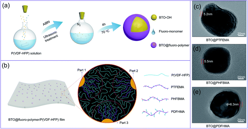
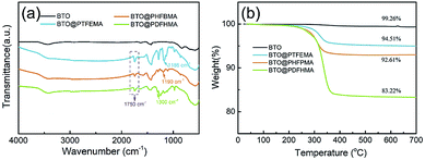
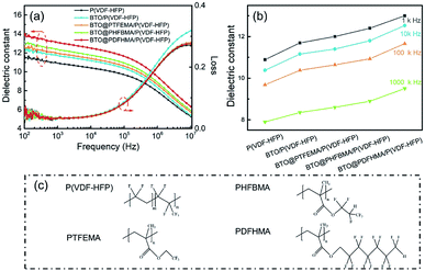
The BTO@fluoroalkyl methacrylate core–shell structured nanoparticles were fabricated by a simple chemical polymerization reaction. The preparation process is shown in Fig. 1a. Here, three kinds of fluoroalkyl methacrylate monomers (TFEMA, HFBMA and DFHMA) are employed to investigate the effect of the side chain length of monomer on dielectric properties of polymer nanocomposites. Fig. 1b shows a schematic representation of the interaction between the shell segment structure and P(VDF-HFP) chain segment of three fluorine-containing core–shell particles in the nanocomposite films (part 1, part 2, and part 3 of the dotted circle respectively represent the state of the three particles in the P(VDF-HFP) matrix). As we can see from Fig. 4c, the shell polymers formed by three monomers all have fluorine-containing branched chains, which are highly similar to P(VDF-HFP) chain segments. Therefore, the fluoro-polymer shells can interact well with P(VDF-HFP), and the interaction between the shell and the matrix is more intense as the length of the fluorine-containing segment increases. The TEM images of as-fabricated core–shell nanoparticles are exhibited in Fig. 1c–e. As shown, a stable and dense layer of polymer shell is tightly coated on the BTO_nps surface in all three cases. By controlling the concentration of monomers, the thicknesses of shell layer on the surface of BTO_nps are controlled within 5 to 6 nm. Therefore, the TEM morphology of the nanoparticles directly proves that the preparation of the core–shell structure is successful.In order to understand the chemical structure on the surface of the nanoparticles, the chemical structure of fluoro-polymer shells is characterized by the FTIR (Fig. 2a). It is found that compared with BTO_nps with bare surface, nanoparticles with core–shell structure exhibit significant absorption signals between 1000 and 2000 cm−1 in FTIR spectra. Firstly, all core–shell nanoparticles possess a new absorption bands located at 1750 cm−1, which is associated with C![[double bond, length as m-dash]](https://www.rsc.org/images/entities/char_e001.gif) O. Besides, each core–shell nanoparticles have their own characteristic adsorption peaks, namely 1186 cm−1 for the –CF3 of PTFEMA, 1190 cm−1 for the –CF2 of PHFBMA and 1300 cm−1 for the –CF3 of PDFHMA.35–37 Thus, the results indicate that the fluoroalkyl methacrylate polymer have been successfully coated onto the surface of BTO_nps.
O. Besides, each core–shell nanoparticles have their own characteristic adsorption peaks, namely 1186 cm−1 for the –CF3 of PTFEMA, 1190 cm−1 for the –CF2 of PHFBMA and 1300 cm−1 for the –CF3 of PDFHMA.35–37 Thus, the results indicate that the fluoroalkyl methacrylate polymer have been successfully coated onto the surface of BTO_nps.
To further characterize the shell polymer structure of nanoparticles, TGA experiments have been conducted, as shown in Fig. 2b. With temperature elevated to 700 °C, pristine BTO_nps barely shows weight loss. In contrast, weights of all three types of core–shell structured BTO_nps begin to decrease above 200 °C, and then sharply drop after 300 °C, which results from the thermal decomposition of fluoro-polymer. With complete thermal decomposition, the weight loss at 700 °C of the nanoparticles are about 0.74%, 5.49%, 7.39%, and 16.78% for pristine BTO, BTO@PTFEMA, BTO@PHFBMA, and BTO@PDFHMA, respectively. The results also show that there is a certain amount of fluoro-polymer shell around the BTO_nps, which is consistent with the TEM results.
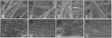
The BTO/P(VDF-HFP) and BTO@fluoro-polymer/P(VDF-HFP) polymer nanocomposites, where the volume fraction of nanofillers is fixed at 15 wt%, are prepared by the nonequilibrium processing method.34 Firstly, the BTO/P(VDF-HFP) and BTO@fluoro-polymer/P(VDF-HFP) composite nanofibers are prepared by a modified electrospinning process. As shown in Fig. 3, the composite nanofibers are smooth, beads-free and of high uniformity. However, some agglomerates of BTO_nps are readily distinguished in the BTO/P(VDF-HFP) composite nanofibers (Fig. 3a), which is attributed to the poor compatibility between inorganic particles and organic polymers. In stark contrast, more homogeneous dispersion of BTO@fluoro-polymer within the P(VDF-HFP) nanofibers could be observed in Fig. 3b–d. But, there still are a slight amount of BTO_nps agglomerates in BTO@PTFEMA/P(VDF-HF) nanofibers. With increasing length of fluoro-polymer side chain, more segment interactions occur between the nanoparticle and the matrix, make the distribution of the BTO@fluoro-polymer nanoparticles more uniform in the P(VDF-HFP) nanofibers. In these four kinds of BTO_nps, BTO@PDFHMA exhibits the best dispersion state. These results indicate that the dispersion of nanoparticles could be greatly improved through introducing a polymer transition layer between BTO_nps and P(VDF-HFP) matrix, verifying the feasibility of core–shell strategies.
After hot-pressing treatment near the melting temperature of P(VDF-HFP), the BTO/P(VDF-HFP) and BTO@fluoro-polymer/P(VDF-HFP) fibrous mats are transformed into dense nanocomposite films, and the thickness of the films is around 12 μm (Fig. S1†). As evidenced by the cross-sectional SEM images of BTO/P(VDF-HFP) films (Fig. 3e), the as-received BTO_nps embedded in polymer matrix show severe agglomeration and are surrounded by the air instead of the polymer matrix. Comparatively, for composites containing BTO@fluoro-polymer particles, there is no finding of particle-matrix debonding and nanoparticles dispersion degree is also improved (Fig. 3f–h). As the fluoro-polymers with branched chain share similar structure with P(VDF-HFP), it can provide strong interface adhesion to the particles by interaction with the P(VDF-HFP) segment, and the adverse effects caused by poor interface are also weakened. Therefore, the compatibility between particles and matrix are enhanced, and agglomerations are overcome in composites containing BTO@fluoro-polymer particles. For instance, PDFHMA has the longest branched chain among three fluoroalkyl methacrylate polymers, which means more chains involved in and stronger interaction between BTO@PDFHMA and P(VDF-HFP). As a result, the best uniform dispersion is achieved in BTO@PDFHMA/P(VDF-HFP).
The frequency dependence of room-temperature dielectric permittivity and dielectric loss for P(VDF-HFP)-based nanocomposite films is presented in Fig. 4a. It can be seen from Fig. 4a that the dielectric constants of the P(VDF-HFP)-based nanocomposites with 15 wt% of BTO_nps or BTO@fluoro-polymer are improved over the whole frequency range from 102 Hz to 107 Hz compared with pure P(VDF-HFP). Fig. 4b shows the comparison of εr for different P(VDF-HFP)-based nanocomposite and pure P(VDF-HFP) at the same frequency. For instance, at a fixed frequency of 103 Hz, the εr of the pure P(VDF-HFP) is only 10.9, while the εr of the BTO/P(VDF-HFP), BTO@PTFEMA/P(VDF-HFP), BTO@PHFBMA/P(VDF-HFP), and BTO@PDFHMA/P(VDF-HFP) nanocomposites is 11.7, 12, 12.4 and 13, respectively. At other fixed frequencies, the εr of the nanocomposites is higher than that of pure P(VDF-HFP). It is obvious that the increase in dielectric constant of BTO/P(VDF-HFP) nanocomposites could be attributed to the high dielectric constant BTO_nps. In addition, Maxwell–Wagner–Sillars (MWS) interfacial polarization is ubiquitous for polymer nanodielectrics, which increases the overall polarization by enhancing dielectric constant.38,39 For BTO@fluoro-polymer/P(VDF-HFP) nanocomposites, by introducing a shell structure between BTO and polymer, the enhancement of interfacial compatibility leads to a homogeneous nanoparticle dispersion and more compact interfaces. Therefore, more interfaces provide higher interfacial polarization, and result in dielectric performance improvement of the BTO@fluoro-polymer/P(VDF-HFP) nanocomposites.
Fig. 4a also shows the dielectric loss tangent of P(VDF-HFP)-based nanocomposite films with different types of BTO_nps. As seen, the BTO@fluoro-polymer/P(VDF-HFP) nanocomposites exhibit a relatively low dielectric loss comparable with pristine P(VDF-HFP). While, the dielectric loss of BTO/P(VDF-HFP) nanocomposite is higher than that of the pristine P(VDF-HFP), especially at high frequency. As we known, the dielectric loss of P(VDF-HFP)-based polymer at high frequency is ascribed to the segmental motions within the amorphous phase of PVDF.40 Compared to BTO@fluoro-polymer/P(VDF-HFP), poor bonding between BTO_nps and polymer matrix in BTO/P(VDF-HFP) nanocomposites allows the polymer segments at the interface to act more freely, which leads to a higher dielectric loss.
Tight bonding between nanofillers and polymer matrices in the BTO@fluoro-polymer/P(VDF-HFP) not only helps to decrease their low-field dielectric loss, but is also beneficial to suppress their high-field electric conduction. Leakage current of all the composite films as a function of electric field are plotted in Fig. 5a. As seen, the BTO/P(VDF-HFP) nanocomposite exhibits the highest leakage current over the whole electric field range, ascribed to the increased amount of charge carriers brought by structural defects (e.g. agglomerations and air holes). For BTO@fluoro-polymer/P(VDF-HFP) composites, the leakage current is significantly suppressed, which benefits from the decreased charge carriers density due to the more homogeneous dispersion and the restricted movement of charge carriers by transition layer. What's more, better suppression of leakage current is achieved due to the fact that longer side chains increase the range of interaction between the transition layer and the P(VDF-HFP) matrix. Hence, BTO@PDFHMA/P(VDF-HFP) exhibits the lowest leakage current, which is comparable with or even lower than that of pristine P(VDF-HFP).
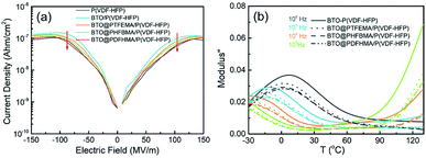 | ||
| Fig. 5 (a) The variation of leakage current on electric fields and (b) the temperature-dependent and frequency-dependent imaginary electric modulus spectra for P(VDF-HFP)-based nanocomposite films. | ||
To further investigate the effect of the fluorine-containing shell branches on the motion behavior of P(VDF-HFP) segments, the temperature dependent and frequency dependent of the M′′ is provided in Fig. 5b. Obviously, it can be observed from Fig. 5b that there are two relaxation peaks. The relaxation peak in low temperature region on the left corresponds to the P(VDF-HFP) segmental motions in amorphous regions, and as the temperature increases, the segment motion becomes easier, which makes the relaxation peak shift to high frequency.41,42 More importantly, compared with BTO/P(VDF-HFP) nanocomposites, the relaxation peak intensity of BTO@fluoro-polymer/P(VDF-HFP) has significantly decreased, especially for BTO@PDFHMA/P(VDF-HFP), the lowest among the four samples. The main reason is that the segmental motion of P(VDF-HFP) is restricted by the fluoro-polymer shells, and the longer the fluoro-polymer branches, the more obvious the restrict effect. In addition to restrict the segmental motion of P(VDF-HFP), fluoro-polymer branches also act as deep traps to capture free charge carriers to improve the insulation performance of nanocomposites. As can be seen from Fig. S2,† the conductivity of BTO@fluoro-polymer/P(VDF-HFP) nanocomposites have been reduced by one order of magnitude compared to the BTO/P(VDF-HFP) nanocomposites, which indicates that the fluoroalkyl methacrylate polymer shell can suppress the electrical conductivity, and this is also consistent with the previous results.
In order to explore the effects of the fluorine-containing shell branches on the motion of P(VDF-HFP) segments, first-principle calculations is performed and the results are presented in Fig. 6. As seen, the charge transfer between different fluoroalkyl methacrylate monomers and the (001) surface of BTO are well distinguished. For TFEMA, HFBMA, DFHMA, obvious charge accumulation regions and charge depletion regions can be found around C![[double bond, length as m-dash]](https://www.rsc.org/images/entities/char_e001.gif) O after interaction with the BTO_nps, and this charge transfer region also responds to the internal atoms of BTO_nps. It is worth noting that for the DFHMA with the longest fluorine-containing segment, in addition to its obvious charge transfer between the BTO_nps, the long fluorine-containing segment will extend outward, providing a point of action for the connection of the particles to the matrix. Therefore, methyl methacrylate with long fluorine-containing segment can not only make a strong interaction with BTO, but also make use of the interaction between its fluorine-containing branch chain and matrix chain segment to make the particles more closely connected with the matrix.
O after interaction with the BTO_nps, and this charge transfer region also responds to the internal atoms of BTO_nps. It is worth noting that for the DFHMA with the longest fluorine-containing segment, in addition to its obvious charge transfer between the BTO_nps, the long fluorine-containing segment will extend outward, providing a point of action for the connection of the particles to the matrix. Therefore, methyl methacrylate with long fluorine-containing segment can not only make a strong interaction with BTO, but also make use of the interaction between its fluorine-containing branch chain and matrix chain segment to make the particles more closely connected with the matrix.
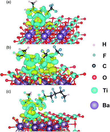 | ||
| Fig. 6 Computed charge density difference of (a) TFEMA, (b) HFBMA, (c) DFHMA absorbed BTO-001. The yellow and blue isosurfaces represent charge accumulation and depletion in the space, respectively. | ||
In addition to the dielectric constant and dielectric loss mentioned above, another important parameter affecting the energy storage density of nanocomposite materials is the breakdown strength. In this study, the Eb of the pure P(VDF-HFP) and nanocomposites are measured using a two-parameter Weibull distribution functions analysis. The Weibull distribution function is described as: P(E) = 1 − exp[−(E/Eb)β], where E is experimental breakdown strength; Eb is calculated from the Weibull distribution that refers to the breakdown strength at the cumulative failure probability of 63.2%; β is a shape parameter to assess the degree of data dispersion and is also a standard for the quality of dielectric performance.43 The Weibull statistical analysis results of the nanocomposite films are shown in Fig. 7. As we can see, the Eb of BTO/P(VDF-HFP) is only 492 MV m−1. The difference in dielectric properties between the filler and the matrix causes the electric field to be concentrated at the interface between them, while the interface between the unmodified particles and the polymer matrix is weakly bonded, leading to the low Eb of BTO/P(VDF-HFP). However, the Eb of the other three nanocomposites containing BTO@fluoro-polymer has a substantial enhancement. For instance, the Eb for BTO@PTFEMA/P(VDF-HFP), BTO@PHFBMA/P(VDF-HFP), and BTO@PDFHMA/P(VDF-HFP) is 569 MV m−1 (β ∼ 15.9), 601 MV m−1 (β ∼ 16.3) and 609 MV m−1 (β ∼ 22.2), respectively. The enhancement in breakdown strength can be explained as the alleviation of distorted electric field near the particle/matrix interfaces. By introducing a fluoroalkyl methacrylate polymer transition layer between BTO_nps and P(VDF-HFP) matrix, the BTO_nps are more closely connected to the P(VDF-HFP) matrix, and the mismatch between particles and matrix caused by the differences in dielectric properties will be eliminated. Therefore, the Eb of these three nanocomposites are greatly improved, and longer fluorinated branched chains can significantly increase the Eb. The results not only demonstrate that the introduction of fluoro-polymer shells has a positive effect on the breakdown strength of the nanocomposites films, but also indicate that longer shell molecular chain branches have positive impact on the breakdown strength of the nanocomposites.
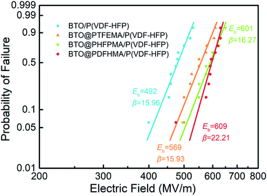 | ||
| Fig. 7 Weibull distributions of electric breakdown strength at room temperature for P(VDF-HFP)-based nanocomposite films. | ||
The energy densities and efficiencies of these nanocomposites are calculated from the electric displacement–electric field (D–E) loops (see D–E loops and calculation details in Fig. S3†), and the discharged energy densities are plotted as a function of electric field in Fig. 8a. Owing to concurrently enhanced εr and Eb that induced by core–shell particle structure in the BTO@fluoro-polymer/P(VDF-HFP) nanocomposites, the Ue are remarkably increased compared with the BTO/P(VDF-HFP) nanocomposite. For instance, a highest Ue ∼ 16.8 J cm−3 at 609 MV m−1 is obtained in BTO@PDFHMA/P(VDF-HFP) nanocomposite, which is 1.46 times Ue of BTO/P(VDF-HFP) nanocomposite (Ue ∼ 11.5 J cm−3 at 492 MV m−1). The Ue of BTO@PTFHMA/P(VDF-HFP) (∼12.5 J cm−3 at 569 MV m−1) and BTO@PHFBMA/P(VDF-HFP) (∼15.1 J cm−3 at 601 MV m−1) are also higher than that of BTO/P(VDF-HFP) nanocomposite. Moreover, η is also an important parameter for evaluating the dielectric performances, as a high η is necessary when dielectric materials are applied to electrical insulation and energy storage devices. Usually, for P(VDF-HFP) based nanocomposite, it has a low discharge efficiency (η) of ∼60%, which means that only about 60% of the energy can be used during energy storage and release. The massive wasted energy will be converted into surface energy of breakdown paths and Joule heat, leading to crippled breakdown strength and lifetime. The variation curves of η versus electric field for nanocomposites are also present in Fig. 8b. Notably, the BTO/P(VDF-HFP) nanocomposite has the lowest η of ∼62% among these four types of P(VDF-HFP) based nanocomposites, which is due to the high dielectric loss during charge/discharge cycling caused by defects that introduced with BTO_nps, such as voids, ions and impurities. Compared with pristine BTO_nps, the BTO@fluoroalkyl methacrylate core–shell structured nanoparticles can restrict the movement of free carriers to suppress the conductivity loss, and also reduce the generation of voids by making use of their similarity to the matrix. Therefore, higher discharge efficiencies have been achieved in nanocomposites with BTO@fluoro-polymer particles, especially for BTO@PDFHMA/P(VDF-HFP) nanocomposite exhibiting a rather high η ∼ 78%.
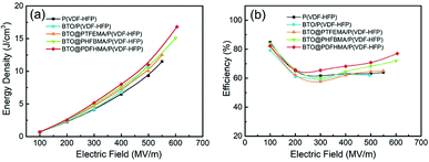 | ||
| Fig. 8 (a) Discharged energy density and (b) charge–discharge efficiency of the nanocomposite films as a function of the electric field calculated from D–E loops in Fig. S3,† respectively. | ||
Conclusion
We have selected three kinds of fluoro-polymers as the transition layer between the particles and the polymer matrix, and use a simple and direct method to coat the transition layer on the surface of the particles to form a stable and dense core–shell structure. The selected fluoro-polymer all have fluorine-containing branched chains, and the side chain length of fluoro-polymer on the properties of polymer nanocomposites are investigated. The side chains of fluoro-polymer have similar segment structure to P(VDF-HFP), which can interact well with the P(VDF-HFP) molecular chain and improve the compatibility between the BTO_nps and P(VDF-HFP). Benefiting from this, the dispersions of BTO_nps are well improved, and good interaction between the segments can make BTO_nps embedded into matrix more tightly. In addition, the core–shell structure can reduce the number of free carriers to suppress the leakage current and enhance the breakdown strength. The longer side chain lengths of fluoro-polymer also have a more positive impact on the performance of the nanocomposites. As a result, with the improvement of these properties, the efficiencies and energy densities of the nanocomposites containing the BTO@fluoro-polymer nanoparticles are found to be significantly increased. These results show that the core–shell structure of fluoro-polymer can combine both the advantages of inorganic particles and polymer matrix, and improve the dielectric properties of nanocomposites. This work also provides a novel and simple path for the preparation of core–shell nanocomposites toward high energy storage density.Conflicts of interest
There are no conflicts to declare.Acknowledgements
This work was supported by the NSF of China (Grant No. 51625202, and 51572141).References
- B. Chu, X. Zhou, K. Ren, B. Neese, M. Lin, Q. Wang, F. Bauer and Q. M. Zhang, Science, 2006, 313, 334–336 CrossRef CAS.
- X. Zhang, Y. Shen, B. Xu, Q. Zhang, L. Gu, J. Jiang, J. Ma, Y. Lin and C.-W. Nan, Adv. Mater., 2016, 28, 2055–2061 CrossRef CAS.
- Q. Li, L. Chen, M. R. Gadinski, S. Zhang, G. Zhang, H. Li, A. Haque, L.-Q. Chen, T. N. Jackson and Q. Wang, Nature, 2015, 523, 576–580 CrossRef CAS.
- Z.-M. Dang, J.-K. Yuan, S.-H. Yao and R.-J. Liao, Adv. Mater., 2013, 25, 6334–6365 CrossRef CAS.
- Q. Chen, Y. Shen, S. Zhang and Q. M. Zhang, Annu. Rev. Mater. Res., 2015, 45, 433–458 CrossRef CAS.
- M. Marz, A. Schletz, B. Eckardt, S. Egelkraut and H. Rauh, CIPS, 2010, pp. 1–10 Search PubMed.
- T. R. Jow, F. W. MacDougall, J. B. Ennis, X. H. Yang, M. A. Schneider, C. J. Scozzie, J. D. White, J. R. MacDonald, M. C. Schalnat, R. A. Cooper and S. P. S. Yen, PPC, 2015, pp. 1–7 Search PubMed.
- Z. Pan, L. Yao, J. Zhai, X. Yao and H. Chen, Adv. Mater., 2018, 30, 1705662 CrossRef.
- Y. Shen, Y. Hu, W. Chen, J. Wang, Y. Guan, J. Du, X. Zhang, J. Ma, M. Li, Y. Lin, L.-q. Chen and C.-W. Nan, Nano Energy, 2015, 18, 176–186 CrossRef CAS.
- Y. Wang, L. Wang, Q. Yuan, J. Chen, Y. Niu, X. Xu, Y. Cheng, B. Yao, Q. Wang and H. Wang, Nano Energy, 2018, 44, 364–370 CrossRef CAS.
- M. Rabuffi and G. Picci, IEEE Trans. Plasma Sci., 2002, 30, 1939–1942 CrossRef CAS.
- V. Tomer, E. Manias and C. A. Randall, J. Appl. Phys., 2011, 110 Search PubMed.
- V. K. Thakur, M.-F. Lin, E. J. Tan and P. S. Lee, J. Mater. Chem., 2012, 22, 5951–5959 RSC.
- H. Luo, D. Zhang, C. Jiang, X. Yuan, C. Chen and K. Zhou, ACS Appl. Mater. Interfaces, 2015, 7, 8061–8069 CrossRef CAS PubMed.
- Y. Song, Y. Shen, H. Liu, Y. Lin, M. Li and C.-W. Nan, J. Mater. Chem., 2012, 22, 16491–16498 RSC.
- Q. Wang and L. Zhu, J. Polym. Sci., Part B: Polym. Phys., 2011, 49, 1421–1429 CrossRef CAS.
- J. Y. Li, L. Zhang and S. Ducharme, Appl. Phys. Lett., 2007, 90, 132901 CrossRef.
- H. Luo, X. Zhou, C. Ellingford, Y. Zhang, S. Chen, K. Zhou, D. Zhang, C. R. Bowen and C. Wan, Chem. Soc. Rev., 2019, 48, 4424–4465 RSC.
- Y. Niu, Y. Bai, K. Yu, Y. Wang, F. Xiang and H. Wang, ACS Appl. Mater. Interfaces, 2015, 7, 24168–24176 CrossRef CAS.
- R. Zhao, J. Zhao, L. Wang and Z.-M. Dang, J. Appl. Polym. Sci., 2015, 132 CAS.
- P. Kim, N. M. Doss, J. P. Tillotson, P. J. Hotchkiss, M.-J. Pan, S. R. Marder, J. Li, J. P. Calame and J. W. Perry, ACS Nano, 2009, 3, 2581–2592 CrossRef CAS.
- P. Kim, S. C. Jones, P. J. Hotchkiss, J. N. Haddock, B. Kippelen, S. R. Marder and J. W. Perry, Adv. Mater., 2007, 19, 1001–1005 CrossRef CAS.
- K. Yu, H. Wang, Y. Zhou, Y. Bai and Y. Niu, J. Appl. Phys., 2013, 113 Search PubMed.
- Q. Li, G. Zhang, F. Liu, K. Han, M. R. Gadinski, C. Xiong and Q. Wang, Energy Environ. Sci., 2015, 8, 922–931 RSC.
- Y. Niu, F. Xiang, Y. Wang, J. Chen and H. Wang, Phys. Chem. Chem. Phys., 2018, 20, 6598–6605 RSC.
- S. Siddabattuni, T. P. Schuman and F. Dogan, ACS Appl. Mater. Interfaces, 2013, 5, 1917–1927 CrossRef CAS.
- L. Xie, X. Huang, C. Wu and P. Jiang, J. Mater. Chem., 2011, 21, 5897–5906 RSC.
- M. N. Tchoul, S. P. Fillery, H. Koerner, L. F. Drummy, F. T. Oyerokun, P. A. Mirau, M. F. Durstock and R. A. Vaia, Chem. Mater., 2010, 22, 1749–1759 CrossRef CAS.
- X. Pang, Y. He, B. Jiang, J. Iocozzia, L. Zhao, H. Guo, J. Liu, M. Akinc, N. Bowler, X. Tan and Z. Lin, Nanoscale, 2013, 5, 8695–8702 RSC.
- K. Jiang, C. Ye, P. Zhang, X. Wang and Y. Zhao, Macromolecules, 2012, 45, 1346–1355 CrossRef CAS.
- K. Yang, X. Huang, L. Xie, C. Wu, P. Jiang and T. Tanaka, Macromol. Rapid Commun., 2012, 33, 1921–1926 CrossRef CAS.
- L. Xie, X. Huang, Y. Huang, K. Yang and P. Jiang, J. Phys. Chem. C, 2013, 117, 22525–22537 CrossRef CAS.
- H. Luo, S. Chen, L. Liu, X. Zhou, C. Ma, W. Liu and D. Zhang, ACS Sustainable Chem. Eng., 2018, 7, 3145–3153 CrossRef.
- J. Jiang, X. Zhang, Z. Dan, J. Ma, Y. Lin, M. Li, C.-W. Nan and Y. Shen, ACS Appl. Mater. Interfaces, 2017, 9, 29717–29731 CrossRef CAS.
- S. K. Papadopoulou, C. Tsioptsias, A. Pavlou, K. Kaderides, S. Sotiriou and C. Panayiotou, Colloids Surf., A, 2011, 387, 71–78 CrossRef CAS.
- B. Jiang, L. Zhang, J. Shi, S. Zhou, B. Liao, H. Liu, J. Zhen and H. Pang, J. Fluorine Chem., 2013, 153, 74–81 CrossRef CAS.
- J. Tan, W. Liu and Z. Wang, Prog. Org. Coat., 2017, 105, 353–361 CrossRef CAS.
- R. Tamura, E. Lim, T. Manaka and M. Iwamoto, J. Appl. Phys., 2006, 100, 114515 CrossRef.
- Z.-M. Dang, L. Wang, Y. Yin, Q. Zhang and Q.-Q. Lei, Adv. Mater., 2007, 19, 852–857 CrossRef CAS.
- P. Fruebing, F. Wang and M. Wagener, Appl. Phys. A: Mater. Sci. Process., 2012, 107, 603–611 CrossRef CAS.
- L. Xie, X. Huang, B.-W. Li, C. Zhi, T. Tanaka and P. Jiang, Phys. Chem. Chem. Phys., 2013, 15, 17560–17569 RSC.
- L. Yu and P. Cebe, J. Polym. Sci., Part B: Polym. Phys., 2009, 47, 2520–2532 CrossRef CAS.
- P. Khanchaitit, K. Han, M. R. Gadinski, Q. Li and Q. Wang, Nat. Commun., 2013, 4, 2845 CrossRef.
Footnote |
| † Electronic supplementary information (ESI) available. See DOI: 10.1039/c9ra06933j |
| This journal is © The Royal Society of Chemistry 2019 |

