
 Open Access Article
 This Open Access Article is licensed under a Creative Commons Attribution-Non Commercial 3.0 Unported Licence
Electrocoalescence of water in oil emulsions: a DPD simulation study and a novel application of electroporation theory
Roar Skartlien *ab,
Sebastien Simonb and
Johan Sjöblomb
*ab,
Sebastien Simonb and
Johan Sjöblomb
aInstitute for Energy Technology (IFE), P.O. Box 40, N-2027 Kjeller, Norway. E-mail: roar.skartlien@ife.no
bDepartment of Chemical Engineering, Ugelstad Laboratory, NTNU, N-7491 Trondheim, Norway
First published on 24th October 2019
Abstract
Pore formation in a surfactant laden oil film between two aqueous electrolyte layers in a DC field was studied using DPD (Dissipative Particle Dynamics molecular simulation). This setting represents the final stage of an electro-coalescence process between water droplets in oil, where the oil film has drained out to nanometer thickness. We introduce a novel model for the coalescence probability based on electroporation theory for lipid bilayers, and an equation for a threshold electric potential above which coalescence is highly probable. Excess electric forcing (pinching) of the oil film occurred locally due to charge density fluctuations in the electrolyte, and this could lead to the formation of unstable, expanding pores and coalescence between the aqueous domains. Such unstable pores can form at lower electric potentials when the cohesive energy in the surfactant layer (primarily line tension) is lowered by adding demulsifier, or when demulsifier causes a morphology change in the surfactant layers with local areas that have lower surfactant density. In conclusion, higher ion concentrations in the electrolyte, higher electric field strength, and lower cohesive energy in the surfactant layer increased the coalescence probability.
1 Introduction
Electrocoalescence is used in the oil industry to increase the coalescence rate of water droplets in crude oil where indigenous surfactant acts as an emulsion stabilizer. For example, asphaltenes form interfacial “coatings” that may prevent coalescence1,2 unless an external E-field is applied and/or demulsifier is added. For coalescence to happen in general, the surfactant layers must first be brought together by draining the oil film between the droplets to essentially form a bilayer of surface active compounds. In more general terms, one can expect a very thin oil film of a few nanometers between the surfactant layers, and we refer to this as the SOS-layer (surfactant/oil/surfactant). The crucial second step is to open the SOS-layer to form an expanding aqueous channel between the water droplets.Although electrocoalescence is a widely used method in the industry, a reliable model framework that ties the coalescence probability to the associated molecular processes has been lacking.3 The motivation for the current work is to provide a basic foundation for a model framework that can account for molecular interactions and processes. This can eventually be developed into a predictive model for specific systems with surface active compounds in produced oil/water emulsions. The processes behind electroporation of lipid bilayers share many common factors with electrocoalescence since it is the rupture of interfacial surfactant layers or layers of surface active compounds that is essential for coalescence between water droplets in oil to occur. In the current work we used DPD (Dissipative Particle Dynamics) simulations to get more insight into the molecular processes, and a mathematical model of the pore formation delay was developed from electroporation theory.
Electroporation theory of lipid bilayers has been studied extensively in the context of cell membranes in biological systems.4,5 Pores through the bilayer open and close (with diameters of a few nanometers) by random kinetic molecular motion at a given temperature. The theory predicts that if a seeded pore opening is larger than a critical size corresponding to a maximum pore energy, it becomes unstable and the pore inflates to large macroscopic diameters of less energy. This, in turn, leads to coalescence. The effect of the E-field is that the critical pore diameter is reduced so that the formation rate of unstable pores increases. This effect comes about via the electric potential energy stored over the bilayer (or more generally, the SOS-layer) due to charges in the electrolyte. Opposite charges over the SOS-layer may build up from charge separation in the electrolyte induced by the external E-field (analogous to charging a capacitor). These effects should also be present in oil/water emulsions with unstable expanding pores corresponding to droplet coalescence events. Demulsifiers are used to increase the coalescence rate between droplets with or without an electric field. The cohesive energy (or line tension) in the surfactant layers may be lowered by adding demulsifier, and this should also increase the coalescence probability further in the presence of an electric field.
Demulsifier-molecules are generally oil-soluble polymeric and polar chains that interact with the surfactant at the oil/water interface. The efficiency of a demulsifier is primarily controlled by the polarity and the length of the chains.6 The polar groups are able to interact strongly with the water side of the interface or with the polar groups of the surfactant, and both effects may have the potential of displacing the surfactant molecules and weakening the surfactant layer locally. Furthermore, the demulsifier can reduce the mean adsorbed density of surface active species such as asphaltenes.2 Another demulsifier effect that can occur for sufficiently long chains is the formation of molecular bridges between the surfactant layers, through the thinned oil film.7 A representative demulsifier structure is alkyl phenol resin alkoxylate composed of a chain of hexagonal carbon rings, each connected to a chain of alkanes or alkenes, and a chain with a strongly polar end-group.† Another representative demulsifier structure is tri-block copolymer where the central polypropylene glycol group is flanked by two polyethylene glycol groups.‡
In the presence of an E-field, the droplet kinetics in the emulsion that occur prior to coalescence is likely to play a significant role for the coalescence mechanism. The water droplets become polarized in general, resulting in electrostatic attraction between the droplets,3 and opposite charges build up at either side of the droplet if the water contains significant amounts of mobile ions. If an alternating E-field (AC) is used, the degree of charge separation within the droplets is dependent on the AC frequency versus the mobility timescale of the ions. If the droplets are well separated they may have time to deform and stretch along the direction of the field (depending on the frequency), forming conically shaped tips at the contact point between the droplets. A strongly curved surfactant layer may even fracture if the radius of curvature is sufficiently small. On the other hand, if the emulsion is dense (dense packed layers) and strongly influenced by gravity or buoyancy forcing before the E-field is applied, the droplets are adjacent to each other with essentially drained oil films and the contact area between the droplets is approximately planar when the E-field is turned on. Planar films is the background for our simulation setup, and in fact, this lamellar setup is the only feasible starting point for the kind of nano-scale molecular simulations we use.
Electrostatic molecular dynamics simulations can be used as a guide to identify the basic molecular mechanisms in electroporation.5,8 We implemented an established electrostatic DPD (Dissipative Particle Dynamics) method due to Groot,9 which uses the PPPM (particle–particle particle–mesh) approach. We considered a thin oil layer coated with surfactant and demulsifier on either side. This surfactant-oil-surfactant “SOS-layer” was embedded in an aqueous electrolyte. An electric field was applied normal to this layer to drive the formation of expanding pores through the SOS-layer, representing a coalescence event between water droplets in oil. The basic research questions we addressed were how the demulsifier affects the formation probability of unstable pores in the presence of an electric field, and whether electroporation theory could be used to describe the results.
2 The DPD model and simulation setup
We implemented Groot's DPD approach in our own DPD software. A detailed description of the basic DPD-technique without electric fields can be found in the now-extensive literature.10–12 DPD uses approximate interaction potentials corresponding to the forces between molecular groups or segments. These forces can be obtained in a rigorous fashion by averaging over the resolved potentials arising from the detailed atomic structure in these segments.13,14 In the standard DPD approach, the resulting coarse grained force is strictly repulsive due to a domination of the short range repulsive part of the single-atom interaction potentials. This force is modelled by a linearly decreasing function with increasing distance. The force between groups or beads i and j can be written FCij = −∂rU(rij) with a potential
 | (1) |
 is quadratic in the bead distance rij. Thus, the potentials always have the same shape, but they are of varying amplitude controlled by the interaction parameters aij.
2.1 The electrostatic part of the DPD method
For electrolytes, one usually assumes electrostatic conditions and solves only the Poisson equation for the electric field, given the charge density distribution in the volume of interest. The electric force on a charged bead can then be derived once the potential is known. Electrostatic DPD have been implemented to study polyelectrolytes,15 acid/base reactions including proton transfer16 and recently by our group with partitioning of acids over oil/water interfaces.17In the method of Groot,9 the Poisson equation is solved on an Eulerian grid given a smeared charge distribution. The Poisson equation governs the generation of the electric field,
∇·(εE) = e(Z+n+ − Z−n−) ![[triple bond, length as m-dash]](https://www.rsc.org/images/entities/char_e002.gif) enq = ρq, enq = ρq,
| (2) |
| E = −∇ϕ. | (3) |
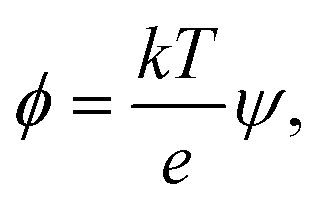
The dimensionless electrostatic potential ψ is defined by
 | (4) |
 | (5) |
![[small rho, Greek, tilde]](https://www.rsc.org/images/entities/char_e0e4.gif) = 3. Groot9 defines
= 3. Groot9 defines| ∇·(p(r)∇ψ) = −Γρ*(r), | (6) |
 | (7) |
= 3. The volumetric charge distribution from a single point charge is represented by qcf(r), with a symmetric weight function f(r), and qc is the charge of the ion in question (charge of a DPD bead). The total charge density at a given point in space (the source term in the Poisson equation) is the sum over all overlapping smeared charge distributions from all ions.
The Poisson equation is solved by iteration,
ψn+1 = ζ[∇·(p∇ψn) + Γ![[small rho, Greek, macron]](https://www.rsc.org/images/entities/char_e0d1.gif) eRc3] + ψn, eRc3] + ψn,
| (8) |
 | (9) |
 | (10) |
The smeared charge distribution that is used to solve for the electrostatic field, must also be used to evaluate the force on an ion. This electric force is then added to the short range molecular forces that are used in standard DPD.
Iterations are used to solve the Poisson equation rather than more costly full-domain matrix inversions. Groot demonstrated correct double layer behavior in an electrolyte over a charged surface, consistent with Poisson–Boltzmann theory. The iterations correspond to slowly converging Jacobi-iterations, and as such, it is difficult to evaluate when and if the solution of the electric field has converged. This is alleviated by starting the iteration at each DPD timestep with the converged electric potential from the previous timestep. Thus, over time, one obtains a solution of the electric field that is accurate, provided that the converged solution represents a stationary configuration (no larger scale, rapid dynamics).
2.2 Simulation setup
We used a lamellar setup with a thin oil layer coated with a surfactant layer at either side (at the W/O and O/W interfaces). This constitutes a surfactant coated oil film (a SOS-layer), embedded in a larger electrolytic water domain (Fig. 1). The full duration of the simulations was about one microsecond, and the domain size was Lx × Lz × Ly = 8.1 × 8.1 × 15.9 nm, with Ly being the domain size perpendicular to the surfactant layer. For comparison, surfactant monolayers are on the order of a few nanometers thick. We used periodic boundary conditions in all three directions. A periodic boundary in the direction parallel to the SOS layer does not allow for further film draining. Thus, we considered the current setup as the final phase before coalescence, where the oil film is thin enough to allow for poration events. | ||
| Fig. 1 An overview of the simulation domain at early (close to the initial condition) and at late times (charge separated conditions). The electric potential deviation from the time averaged potential is shown by the grey scale, and the evolution of the electric potential due to partial charge separation in the electrolyte is evident with a locally positive perturbation near the upper interface. The E-forces on the ions pinches the SOS-layer centered at y = 0. Yellow symbols show positive ions, while blue symbols show negative ions. The surfactant is marked with red symbols, and the demulsifier with turquoise symbols. Both species are located at the oil/water interface. | ||
Fig. 1 shows the deviation in the electric potential from the time averaged potential. At late times, charge separation has had time to develop with an excess of +charges and a positive perturbation of the potential on the upper side of the oil layer and an excess of –charges on the lower side of the oil layer. An equilibrium situation developed, with full charge separation in the electrolyte volume. Significant charge separation will also occur for alternating potentials (AC) if the mobility of the ions is sufficiently fast relative to the AC frequency. The opposite charges over the SOS layer provided a perpendicular, compressive forcing. Thermal ionic density fluctuations (also seen in Fig. 1) resulted in a stochastic component with excess forcing in local areas that could lead to poration there. Current flowed through the opened pores, with a gradual elimination of the charge difference over the oil layer (Fig. 2). The external electric field strength and the cohesive energy between the surfactant molecules were varied. The electric field was applied over the domain perpendicular to the SOS layer, and had three values E = 0.0, 0.5, 1.0 normalized to 18 kV cm−1. The maximum value of 18 kV cm−1 is moderately larger than for a typical electrocoalescence case with a field strength of a few kV cm−1.
 | ||
| Fig. 2 One realization of the aggregating case D, with E = 1.0 (18 kV cm−1). Left: panel (a) shows a developed pore through the thin oil layer, and panel (b) shows the surfactant and demulsifier as well. The M-type surfactant is shown with red (head beads) and green (tail beads) and the N-type demulsifier with turquoise (head beads) and violet (tail beads). Middle: a side view with positive (red) and negative (blue) ions in the water/electrolyte phase. Current is flowing through the pore as indicated by the arrow (positive charges move down and negative move up). Right: the same side view with only oil and surfactant/demulsifier mixture showing. The horizontal extent of the domain is 8.1 × 8.1 nm, and the vertical extent is 15.9 nm. | ||
We used a friction coefficient of γ = 4.5, coarse graining parameter = 3, and temperature  . We note that γ controls the viscosity of the system (we assume equal oil and water viscosities), represents the number of water molecules per water bead, and
  is the normalized kinetic temperature. A general normalized cutoff radius of
 ![[r with combining tilde]](https://www.rsc.org/images/entities/i_char_0072_0303.gif) c = 1.0 was set for the molecular forces (beyond which the DPD forces are set to zero), with a normalizing length unit of Rc = 0.64 nm.
c = 1.0 was set for the molecular forces (beyond which the DPD forces are set to zero), with a normalizing length unit of Rc = 0.64 nm.
We used 12![[thin space (1/6-em)]](https://www.rsc.org/images/entities/char_2009.gif) 000 beads to represent surfactant, oil, water, and ions. The number of water beads was 9000, the number of oil beads was 1200, the number of surfactant and demulsifier beads was 1800, and the number of ions in the water was 1800. The bulk ion concentration was about 25% by volume and charge neutrality was imposed in the domain (an equal number of positive and negative charges). The ions in the water were assumed to have the same DPD interaction parameter and mass as the water beads. The oil layer was relatively thin, comparable to either surfactant layer (Fig. 1). Nearly full surfactant coverage on the interfaces was implemented to achieve maximum stability against coalescence.
000 beads to represent surfactant, oil, water, and ions. The number of water beads was 9000, the number of oil beads was 1200, the number of surfactant and demulsifier beads was 1800, and the number of ions in the water was 1800. The bulk ion concentration was about 25% by volume and charge neutrality was imposed in the domain (an equal number of positive and negative charges). The ions in the water were assumed to have the same DPD interaction parameter and mass as the water beads. The oil layer was relatively thin, comparable to either surfactant layer (Fig. 1). Nearly full surfactant coverage on the interfaces was implemented to achieve maximum stability against coalescence.
The simulations were run to an equilibrium state characterized by a constant kinetic temperature over time, and a fully separated charge distribution in the water phase. As the surfactant was neutral, there was no double layer formation in the aqueous phase near the interface, but rather a region of mostly positive ions near one interface, and a region of mostly negative ions near the other interface.
 | (11) |
Water is denoted W, and oil O, and the associated interaction parameters were taken from Rekvig et al.18 The force joining the heads with the tails is governed by a harmonic potential18 associated to an interaction parameter of 100. H and h denote hydrophilic “head beads”, and T and t lipophilic “tail beads”. For the tail–water, tail–oil and head–water, head–oil interaction parameters we took the values used by Li et al.19 for sodium dodecylbenzene sulfonate (SDBS). This is one example of an interfacially active molecule that is more soluble in oil than in water (due to its long hydrocarbon chain), representing the O/W partitioning behavior of an indigenous surfactant. To obtain stronger surfactant–surfactant interactions and more resistance towards poration, we used a two-bead tail structure and a two-bead head structure. The surfactant, labeled M, had the structure H − H − T − T and the demulsifier, labeled N, was considered to be a simplistic demulsifier-model with the structure h − h − t − t. Both the surfactant and demulsifier were assumed to be charge neutral. It can be argued that a more realistic demulsifier model would consist of a (polar) head group on either end of the molecule, or even polar groups dispersed along the full length of a longer molecular structure. However, we are of the opinion that the simplistic approach generates structural changes in the SOS layer that are sufficiently general and relevant.
We used four combinations A, B, C and D of surfactant and demulsifier interaction properties as shown in Table 1. Only the interactions HH, hh, TT, tt and Hh, Tt changed values as indicated (representing self-interactions and mutual interactions respectively between surfactant and demulsifier). These particular parameters were considered to be free variables for adjusting the surfactant and demulsifier interactions. All head–tail interaction parameters were set to 80, equal to that of the oil/water interaction. Two combinations (A, B) had unequal M ≠ N surfactant and demulsifier characteristics, with low mutual solubility. Two combinations (C, D) had identical types M = N with mutual attraction and aggregation to varying degree. It is a natural assumption that both relatively strong repulsion (Case A) and strong attraction (Case D) may leave vacated regions in the surfactant layer where poration can occur with higher probability. However, we shall see that these cases generate very different results.
| Case | Hh | HH = hh | Tt | TT = tt |
|---|---|---|---|---|
| A: M ≠ N strong repulsion | 100 | 30 | 100 | 30 |
| B: M ≠ N weak repulsion | 50 | 30 | 50 | 30 |
| C: M = N weak attraction | 30 | 30 | 30 | 30 |
| D: M = N strong attraction | 5 | 5 | 5 | 5 |
2.3 Comparison of energies in the DPD system
The electric energy has to overcome the cohesive energy of the SOS layer for electroporation to occur. The electric potential is
 | (12) |
| Δϕ = Δψ × 26 mV, | (13) |
The electric potential energy Eϕ = 1/2QΔϕ, must be significant compared to the thermal energy and the cohesive energy of the SOS-layer for the E-field to have any effect. The associated charge is Q = CΔϕ. The capacitance C of a certain interfacial area A is C = εA/δ where ε is the effective permittivity of the SOS layer. The relevant area A corresponds to the characteristic length scale of charge fluctuations parallel to the SOS layer, and Δϕ must be interpreted as the local voltage over the film, averaged over this area. With an estimated Q ≃ 10e over the area A in our simulations, Eϕ ≃ 64 × 10−19 J = 150 kT which constitutes a substantial electric forcing compared to thermal fluctuations, and the thermal energy serves to drive the system with only moderate stochastic forcing.
Pore formation can occur locally only if the electric energy is comparable to the cohesive energy of the SOS layer. In DPD, the potential energy due to pairwise molecular interactions is
 | (14) |
 | (15) |
The energy difference between two configurations of the SOS layer is
| ΔU ≃ kTδarc/8 | (16) |
 | (17) |
The end state B has higher energy than the initial state A due to the generation new surface area when the pore opens. As a rough estimate for the energy change over a pore area, we assume that about 10 molecules occupy the pore area initially, where each molecule has 5 effective “bead” interactions with the neighbor molecules. The average interaction parameter is about 50. The cohesive energy of state A before the pore opens is then of the order of
 | (18) |
Thus, it is reasonable to expect that the energy difference between an intact layer and a layer with an open pore is of the order of ΔU ≃ 100 kT, and this is sufficiently small to allow for electroporation with Eϕ ≃ 150 kT.
3 Results from simulations
3.1 Pore formation mechanisms
The DPD simulations captured pore formation events that responded to varying electric field strengths and the surfactant and demulsifier mixture properties. Fig. 2 shows the aggregating case D after the pore has formed (with E = 1.0 or 18 kV cm−1). Panel (a) shows a top view of the oil layer with an open pore. Panel (b) shows the surfactant and demulsifier in addition to oil. The surfactant (M-type) is shown with red (head beads) and green (tail beads). The demulsifier (N-type) is shown with turquoise (head beads) and violet (tail beads). Panel (c) displays a side view with positive ions (red) and negative ions (blue) in the electrolyte and a current is flowing through the pore (arrow) with positive and negative ions moving in opposite directions. Panel (d) shows the oil layer with surfactant on either side (the SOS layer).We are confident that long lasting pores with diameters well above 2 nm represent unstable pores, and the critical pore diameter was estimated to about 0.5 nm (from electroporation theory in Section 4.1). The fully extended pore area was in the range 4–8 nm2. The reason for not inflating further at this pore size (above the critical one) is simply that lateral expansion is restricted by the limited size of the domain together with using periodic boundary conditions. The surfactant and oil layer are compressed laterally when the pore opens, limiting the size of the pore.
From Fig. 2 panel (b), it is seen that the species M and N are not perfectly homogenised (but appear as patches of M and patches of N) even though M and N have identical properties for case (D and C). The reason for this is that the molecules are not perfectly homogenised initially and the patchy appearance later is a memory effect from the initial configuration. The two different species were indeed assigned random positions on the interfacial plane. Such a random two-component distribution will however appear heterogeneous (if we imagine a version of perfect mixing, for example a chess board pattern, it would be a non-random distribution). The surfactant and demulsifier covered the entire interface, leaving no hole initially even if a patchy structure was observed.
The left hand panel in Fig. 3 shows the time delay between the start of the simulation to the onset of pore formation. This delay corresponds to the time it takes for an unstable pore to form, after the E-field is turned on. Each combination of surfactant mixture and electric field strength was run in two independent simulations to obtain two independent realizations of the time delay. Direct evaluation of the mean and variance of the pore formation delay by running an ensemble of simulations is very time consuming and this was not conducted. The two different realizations are shown in the figure.
 | ||
| Fig. 3 Left: pore formation delay since the DC field was turned on. Right: maximum current through the pores at late times. Case A: stars, case B: diamonds, case C: triangles, case D: squares. Two realizations were run for each case. | ||
The difference in delay between the field strength 0.5 and 1.0 is not dramatic, but there is clearly a shorter average delay with increasing field strength. Furthermore, case D (strong attraction) tends to have larger delays than cases A, B and C. An increasing electric field strength forces or pinches the SOS layer more for a given charge difference over the SOS layer, and this may trigger pore formation at earlier times. The delay may also be influenced by the relaxation time of the surfactant to reorganize into a new equilibrium configuration around the pore opening. There was no pore formation for zero field except for case D that produced a surfactant and demulsifier filled pore through spontaneous bridging over the oil film. The mean delay time can be derived from electroporation theory (as shown later), incorporating the field strength, ion density and the cohesive energy in the SOS layer.
When a pore forms, current starts flowing through the pore opening to neutralize the charge difference over the SOS layer. The current is determined by the field strength and the pore diameter (with a certain electric resistance), in accord with Ohms law. The developed current at late times (end of the simulation), as a function of the applied field strength is shown in the right panel of Fig. 3. Increasing field strength increases the current simply by virtue of Ohms law, with pore diameters (electric resistance) that did not vary much between the cases. Some infilling by surfactant or demulsifier molecules modulated the resistance in the pore and hence the current. For very long times, the current decreased to zero as the charge difference over the SOS layer was neutralized.
3.2 Surfactant and demulsifier effects on pore formation
The simulations for cases A, B, C (repulsion and weak attraction) produced quite similar behavior in terms of pore morphology. Thus, more or less the same results were obtained when the surfactant was incompatible or weakly interacting with the demulsifier. Fig. 4 shows the morphology for case A for all three field strengths, with surfactant and demulsifier covering the entire interface, except for the higher field strength where pores have developed. The pore formation time delays were also similar for a given field strength (Fig. 3). The reason for this similarity is possibly the fully covered interface that give comparable resistance to electric forcing. Pores still formed when the field was strong enough, and the developed pores were to some degree filled in with surfactant or demulsifier due to the lateral repulsion between the two. A preliminary conclusion is that these cases represent a “non-demulsifier” behavior with little variation between different cases. | ||
| Fig. 4 Case A: the upper row shows the oil, surfactant and demulsifier, while the lower row shows only the pore geometry through the oil layer. These snapshots were taken at the end of the simulation, after the pore and current through it had stabilised. The normalized field strength is indicated. | ||
Case D (strong attraction) for distinct aggregation between surfactant and demulsifier is more representative of the effect of real demulsifiers where the polar groups of the demulsifier are able to link up to the surfactant polar groups. This offered larger surfactant/demulsifier density variation over the oil layer and more sites where pores could form. The pore formation delays were marginally larger possibly due to increased relaxation time of the surfactant/demulsifier layers. As shown in Fig. 5, the pores were now well defined with sharp edges and could have surfactant free interiors (here for the highest field strength).
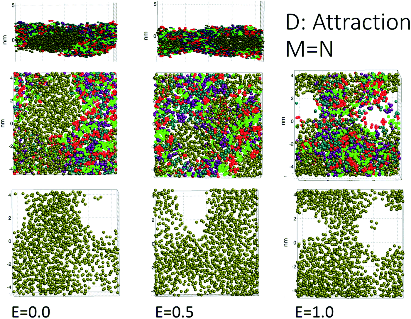 | ||
| Fig. 5 Case D: aggregating surfactant and demulsifier. Pores could also form without an applied field due to bridging of the surfactant/demulsifier mix over the oil layer (the uppermost panels show a side view). For larger field strength the surfactant/demulsifier did not occupy the pore and left a conducting channel (that can expand and lead to coalescence in an emulsion). | ||
For the intermediate field strength of E = 0.5, there was no current flowing through the pore for case D (Fig. 3), since it was completely filled with a surfactant/demulsifier layer (Fig. 5). It is an interesting possibility that coalescence may be prevented by filling the newly opened pore if the mobility of the demulsifier and/or surfactant is sufficient. For E = 0, the surfactant and demulsifier were able to form a pore in the oil by reconnecting the hydrocarbon tails through the oil layer.
3.3 Pore formation efficiency in terms of generic demulsifier behavior
Cases A to D represent an increasing degree of attraction between the surfactant and demulsifier molecules, from (A) strong repulsion between two distinct molecular groups, to (D) attraction between these groups. Case A models a case in which a “demulsifier” N competes with surfactant M for adsorption sites on the oil/water interface, being mutually incompatible or insoluble in each other (Fig. 4). Case B is a variation over the same case but with weaker repulsion. However, the expansion of these border lines will be heavily constrained when the compressibility of these molecular islands is limited. The border between islands of M and N domains in the interface allows for lower interfacial concentration, partially exposing the oil layer where a pore can open up. Thus incompatible surfactant and demulsifier may not be very effective for enhancing the pore formation probability. These cases may be regarded to have “non-demulsifier” behavior, in contrast to demulsifiers where the polar groups are able to attract and interact strongly with the surfactant polar groups.Case D (Fig. 5) represents aggregation of the surfactant into islands of a mixture of surfactant and demulsifier, leaving larger vacated areas of exposed oil film. A realization of scenario D could be obtained by the typical petroleum demulsifier, with long polymer segments that attach to a larger number of surfactant molecules via polar interactions. Furthermore, strong interaction between the demulsifier and surfactant may also result in bridging through the oil layer (as noted above for case D for the lower field strengths).
4 A probabilistic electroporation coalescence model
4.1 Application of lipid bilayer electroporation theory
Electroporation in lipid bilayers has been studied extensively in cell biological contexts, with poration of phospholipid cell membranes and vesicle membranes.4,22 Electroporation theory would describe the most simple emulsion system with brine droplets in oil, covered with amphiphilic, oil soluble surfactant. When the oil film is completely drained, the two amphiphilic surfactant layers form a lipid bilayer membrane. Electroporation theory is therefore a natural starting point for the development of a theory for electrocoalescence in oil/water emulsions.A net charge difference over the lipid bilayer corresponds to an electric energy stored in a “membrane capacitor”. Pore formation removes a part of this energy locally, and hence it may be favorable for pores to form with a minimization of the total membrane energy. According electroporation theory, two types of “ideal” pores may form: the “non-conducting pore” or hydrophobic pore which simply corresponds to a sideways displacement of the amphiphiles. The other pore type is the “conducting pore” or the hydrophilic pore where the polar head groups line the opening of the hole, and the lipid tails bend into the hydrocarbon interior of the membrane. It is likely that a small nonconducting pore opens first, before it develops into a conducting pore.4 However, these two clean-cut ideal scenarios may not be entirely realistic for complex surfactant systems originating from petroleum, and we will not distinguish them in great detail below.
The energy required to generate a conducting pore of radius r is,23
 | (19) |
The terms are respectively the energy required to form the inner perimeter of the pore (γ is the line tension in terms of interfacial energy per unit distance), the surface energy lost between the intact membrane and the pore opening (σ is the interfacial tension), the steric interaction energy between the lipid heads over the pore diameter in terms of the parameter b (one can also include bending energy here), and the lost electric energy due to the removal of the membrane capacitance in the pore area. The transmembrane voltage is V (potential difference over the bilayer). The constant
 | (20) |
We introduce a modified form that ignores the steric interaction over the pore, but incorporates the demulsifier and surfactant into the line and interfacial tensions,
| ϕp(r) = 2π(γo + γs)r − π(σo + σs)r2 − πapV2r2. | (21) |
The total line tension in the pore opening is γ = γo + γs, where γo is the line tension due to the oil, and γs is the line tension due to the surfactant and demulsifier mix. The line tension corresponds to the energy required to open up a pore perimeter in the surfactant/demulsifier layer (and oil layer) and this is equal to the cohesive energy between the molecules involved. We expect that the line tension decreases when demulsifier is mixed into the surfactant layer, so that less energy will be required to open a pore. A reduction in line tension is also possible through a reduction of surfactant/demulsifier surface density locally through aggregation, or more globally by desorption.
The surface energy lost by replacing the SOS-layer by a pore is given in terms of the total interfacial tension σ = σo + σs towards the aqueous domain, where σo is the oil/water interfacial tension, and σs is the (negative) change introduced by the surfactant and demulsifier mix. Desorption of surfactant (or local density reduction) increases the interfacial tension through this term and this will also reduce the pore formation energy. In our simulations, the characteristic magnitudes of the different terms were 2πγor ∼ 60 kT, 2πγsr ∼ 100 kT, πσr2 ∼ 30 kT, πapV2r2 ∼ 100 kT, estimated by considering the DPD interaction parameters aij.
The pore energy ϕp(r) has a global maximum
 | (22) |
 | (23) |
If the pore radius is above rc, the pore is unstable and expands. Characteristic values are ϕm/(kT) ≃ 10, and rc ≃ 0.2 nm, which are comparable to reported values.23 With this set of equations, it is predicted that the critical pore radius and energy are reduced with increasing electric potential over the SOS-layer, in line with the expectation that an increasing applied E-field increases the coalescence rate between droplets. If the demulsifier reduces the line tension γ, the critical pore energy is reduced even further.
4.2 Average formation frequency of unstable pores
The formation frequency of unstable pores in a lipid bilayer is4| νc = ν0Vme−ϕm/kT, | (24) |
The local charge density and electric potential over the membrane is fluctuating due to thermal motion of the ions in the electrolyte. We may then regard the critical pore radius and energy to be stochastic quantities as well, with the redefinition
 | (25) |
 | (26) |
![[V with combining circumflex]](https://www.rsc.org/images/entities/i_char_0056_0302.gif) = V0 + V′ can be split into the mean potential V0 over the SOS layer and the fluctuating potential. can be taken as the average potential difference over the film over a characteristic radius r* equal to the dominating wavelength of the charge fluctuations parallel to the surfactant film. The critical (maximum) energy of a pore now has a probability density p(ϕm), and the average pore formation rate is then
= V0 + V′ can be split into the mean potential V0 over the SOS layer and the fluctuating potential. can be taken as the average potential difference over the film over a characteristic radius r* equal to the dominating wavelength of the charge fluctuations parallel to the surfactant film. The critical (maximum) energy of a pore now has a probability density p(ϕm), and the average pore formation rate is then
 | (27) |
This constitutes an approximate model for the expectation value of the pore formation frequency, with the effect of demulsifier and electric fields. The inverse pore formation frequency is an average measure of the expected time interval between poration events. The probability distribution for a given number k of poration events to occur in a certain time interval δt is likely to be Poisson distributed as (νcδt)kexp(−νcδt)/k!, with a mean number of events per unit time equal to νc.
The integral (27) can be evaluated numerically by adopting a Gaussian distribution for (and ϕm becomes non-Gaussian). The variance is determined by the fluctuations of the ion density near the SOS-layer, and the average value of the potential is determined largely by the average ion density near the SOS layer. The magnitude of the ion density (and hence the fluctuation magnitude) is determined by the applied field strength (through charge separation) and one may assume that the RMS (root-mean-square) value of the potential fluctuations and the mean value V0 are both proportional to the applied field strength to first approximation. Ion mobility, the drift timescale and the direct influence from temperature of the ion density fluctuations can be taken into account for the next level of approximation.
The measured delay of pore formation after application of the field did have an influence from an initial transient phase of charge separation, Ts, and we assumed a model of the form Td = 1/νc + Ts. For very large potential differences, ϕm → 0, and νc reaches a maximum asymptotic limit ν0Vm. In this limit, Td → 1/(ν0Vm) + Ts.
The RMS values of the potential fluctuations were estimated from the simulation data, and we tuned the characteristic frequency ν0Vm. Fig. 6 for the resulting delay Td shows that the electroporation model (27) qualitatively fits the simulation data (left panel in Fig. 3) in terms of a rapid decline of the delay time as a function of increasing electric potential. The electroporation theory predicts the mean delay time for a given applied potential, whereas the simulation data represent two data points or samples from a delay time probability distribution at the given potential. Therefore, only a qualitative comparison can be done between the model and the current dataset.
 | ||
| Fig. 6 The electroporation theory predicts an exponential variation of the pore formation delay with increasing applied field strength, down to an asymptotic value. | ||
In the limit of small ion density fluctuations relative to the mean ion density, p(ϕm) tends to a delta function and (27) reduces to the more transparent form
 | (28) |
4.3 The threshold potential for coalescence
The model predicts that the delay decreases roughly exponentially with increasing E-field, essentially representing a transition between a no-coalescence regime and a coalescence regime above a certain threshold potential VT over the SOS-layer (here, about 0.5 volt). This threshold can be estimated directly from the low-temperature approximation (28) as
 | (29) |
5 Discussion
The waiting time 1/νc corresponds to the mean rupture timescale24 after most of the macroscopic oil film is drained out, and this can span from extremely small values in comparison to the oil film draining time (for large field magnitudes where ϕm/kT ∼ 1), to extremely large values with essentially no coalescence after the oil film has drained out (for weak fields ϕm/kT > 1). However, the pore formation energy of a specific combination of demulsifier and surfactant must be known a priori in order to generate predictions of the waiting time.Representative demulsifiers for experimental studies are polyethylene glycol oleyl ether (Brij 93), C18H35(OCH2CH2)nOH, n ≃ 2 with molecular weight MW ≃ 357 g mol−1, and HLB ≃ 4, or pluronic triblock PEO–PPO–PEO co-polymer (polyoxyethylene – polyoxypropylene – polyoxyethylene). Pluronic PE8100 has a molecular weight of Mw ≃ 2750 g mol−1, and HLB ≃ 2. Demulsifiers used in the oil industry can be derivatives of pluronics. Another variety is alkyl phenol resin alkoxylate. Incorporation of such molecules in DPD would require detailed models of the surfactant molecular structure as well in order to have a realistic interaction between the two. Refined DPD studies will be possible also with indigenous surfactant in crude oil, such as asphaltene and their aggregates.25 However, such numerical models are very complex and will require a synthesis of our existing models into a fast parallel code. An electrostatic DPD code that can incorporate a realistic combination of both the indigenous surfactant (e.g., asphaltenes) and more detailed demulsifier structures is not currently available to us.
The external electric field E0 drives the charge separation. The ion drift time over the droplet diameter should be much shorter than the period of the AC field to obtain complete charge separation and a situation that corresponds to our simulations. Significant charge separation can also occur for AC fields provided that the mobility μ of the ions in water is high enough. The drift timescale over a droplet of diameter d is given by td = d/vd with a drift velocity vd = μE. This is on the order of 1 cm s−1 for E = 1 kV cm−1. Full charge separation implies micron sized droplets for frequencies on the order of 100 Hz.
vThe model predicts increased coalescence rate with demulsifier as long as the line tension or cohesive energy is reduced (directly, by desorption or by morphology change). To this end, we expect that increased coalescence rate may not always be the case if the interaction between the indigenous surfactant (e.g. a specific group of asphaltenes) and an “unfavorable” demulsifier increases the cohesive energy in the surfactant layer.
When the surfactant was incompatible or weakly interacting with the demulsifier (cases A, B, C) there was a tendency to fill in the oil pores partially with surfactant and demulsifier. The pores were still permeable for current (Fig. 3), and this would neutralize the charge difference over time and prevent further electric forcing. We suggest that the pores of this type are perhaps not as prone to instability and pore inflation as the “clean” pores of the aggregating case D.
Our study assumed that the contact area between the droplets is flat on the nanometer scale. This should be reasonable if the emulsion is dense (dense packed layers) and strongly influenced by gravity or buoyancy forcing before the E-field is applied. For strongly deformed cone shaped droplet interfaces, the curvature at the apex (the droplet tip) is large on a macro-scale. If the curvature is significant also at the molecular scale, the molecular film may fracture because of strong nanoscale deformation, and the pore formation mechanisms we have described do not necessarily apply.
6 Conclusion
The novel aspect of this work is the introduction of electroporation theory to electrocoalescence. A demonstration of how electroporation theory can be applied to this problem was given in terms of a model for the threshold electric potential for coalescence to occur. This threshold can be used as a coalescence criterion after the hydrodynamic draining of the oil film is completed.24 The predicted pore formation time delays from electroporation theory compared well to DPD simulation results.Electroporation theory encompasses all the essential ingredients for the final stages of coalescence where the surfactant film must break: the cohesive energy in the combined surfactant and demulsifier layer (SOS-layer), and the electric energy over the SOS-layer. The challenge is to formulate realistic energy terms for the interaction between the demulsifier and surfactant, and in particular the line tension term. This is possible for well defined oils and surfactants, but may be more complex for crude oil emulsions with indigenous surface active components. The line tension could be calibrated by setting up suitable experiments with surfactant and demulsifier on an oil/water interface, and this would be feasible also for crude oils. Another important ingredient in such an effort will be to obtain a good understanding of the morphological change of the surfactant layer that is induced by a given demulsifier. Such studies could be developed by using neutron scattering techniques that could work for liquid–liquid interfaces.26 AFM (atomic force microscopy) works for adsorbed surfactant layers on dry surfaces27 and for free standing polymer membranes,28 while one can use small angle X-ray scattering techniques29 to study surfactant–demulsifier interactions.
Although our surfactant and demulsifier molecular structures were highly simplified, the DPD simulations revealed generic effects of surfactant and demulsifier interaction on the stability of the SOS layer against electric forcing. We found that well defined, clean pores developed in the presence of an electric field, when the demulsifier caused aggregation of the demulsifier/surfactant mixture. We suggest that this scenario corresponds to representative demulsifiers used in oil/water separation, with long polymer chains that anchor to a large number of surfactant molecules via polar interactions. This interaction reduces the mobility of the surfactant, and may induce aggregation. Incompatible demulsifier or weakly interacting surfactant and demulsifier resulted in pores that could be partially filled with a surfactant and demulsifier mix. If not leading to coalescence, these pores could be electrically conducting and eventually neutralize the electric forcing of the bilayer.
Conflicts of interest
There are no conflicts to declare.Acknowledgements
Erik Bjørklund and Reidar Friberg of Sulzer, Teresa Palmer of IFE, and Jan Vermant of ETH Zurich, provided input to the thought processes. Kenneth Knutsen of IFE provided information on measurement techniques for structures in molecular layers. The activity was a part of “New Strategy for Separation of Complex Water-in-Crude Oil Emulsions: From Bench to Large Scale Separation”, funded by The Research Council of Norway, Wärtsilä Oil and Gas (now Sulzer), Nalco Champion Technologies, Statoil ASA (now Equinor), AkzoNobel (now Nouryon) and Anvendt Teknologi AS. The electrostatic DPD simulator was implemented mainly on basic research funds from IFE, as a strategic initiative (SIS-program). R. S. was also funded as an associate Professor at NTNU/Ugelstad Laboratory.Notes and references
- D. Harbottle, Q. Chen, K. Moorthy, L. X. Wang, S. M. Xu, Q. X. Liu, J. Sjoblom and Z. H. Xu, Langmuir, 2014, 30, 6730–6738 CrossRef CAS.
- D. Pradilla, S. Simon and J. Sjoblom, Colloids Surf., A, 2015, 466, 45–56 CrossRef CAS.
- S. Mhatre, S. Simon, J. Sjöblom and Z. Xu, Chem. Eng. Res. Des., 2018, 134, 117–129 CrossRef CAS.
- J. C. Weaver and Y. A. Chizmadzhev, Bioelectrochem. Bioenerg., 1996, 41, 135–160 CrossRef CAS.
- D. P. Tieleman, BMC Biochem., 2004, 5, 1–10 CrossRef.
- C.-L. Chang and H. S. Fogler, Langmuir, 1994, 10, 1749–1757 CrossRef CAS.
- Y.-L. Yang, M.-Y. Chen, H.-K. Tsao Chen and Y.-J. Sheng, Phys. Chem. Chem. Phys., 2018, 20, 6582–6590 RSC.
- M. Casciola, M. A. Kasimova, L. Rems, S. Zullino, F. Apollonio and M. Tarek, Bioelectrochemistry, 2016, 109, 108–116 CrossRef CAS.
- R. D. Groot, J. Chem. Phys., 2003, 118, 11265–11277 CrossRef CAS.
- P. J. Hoogerbrugge and J. M. V. A. Koelman, Europhys. Lett., 1992, 19, 155 CrossRef.
- R. D. Groot and P. B. Warren, J. Chem. Phys., 1997, 107, 4423–4435 CrossRef CAS.
- P. Español and P. Warren, Europhys. Lett., 1995, 30, 191–196 CrossRef.
- W. G. Noid, J.-W. Chu and G. S. Ayton, J. Chem. Phys., 2008, 128, 244–114 Search PubMed.
- W. G. Noid, J. Chem. Phys., 2013, 139, 090901 CrossRef CAS.
- F. Alarcon, E. Perezac and A. Gama Goicochea, Soft Matter, 2013, 9, 3777–3788 RSC.
- M.-T. Lee, A. Vishnyakov and A. Neimark, J. Chem. Theory Comput., 2015, 11, 4395–4403 CrossRef CAS.
- R. Skartlien, A. Bertheussen, S. Simon and J. Sjoblom, J. Dispersion Sci. Technol., 2017, 39, 1367–1375 CrossRef.
- L. Rekvig, M. Kranenburg, J. Vreede, B. Hafskjold and B. Smit, Langmuir, 2003, 19, 8195–8205 CrossRef CAS.
- X. Li, Y. Liu, J. Tang and S. Li, Acta Mech. Sin., 2009, 25, 583–587 CrossRef CAS.
- S. Freeman, A. Wang and J. C. Weavert, Biophys. J., 1994, 67, 42–56 CrossRef CAS.
- M. R. Anklam, D. A. Saville and R. K. Prud'homme, Polym. Adv. Technol., 2001, 12, 70–84 CrossRef CAS.
- A. R. Thiam, N. Bremond and J. Bibette, Phys. Rev. Lett., 2011, 107, 068301 CrossRef.
- J. C. Neu and W. Krassowska, Phys. Rev. E: Stat. Phys., Plasmas, Fluids, Relat. Interdiscip. Top., 1999, 59, 3471–3482 CrossRef CAS.
- F. Gebauer, J. Villwock, M. Kraume and H.-J. Bart, Chem. Eng. Res. Des., 2016, 115, 282–291 CrossRef CAS.
- R. Skartlien, S. Simon and J. Sjoblom, J. Dispersion Sci. Technol., 2016, 27, 866–883 CrossRef.
- T. A. Oleson, N. Sahai, D. J. Wesolowski, J. A. Dura and C. F. Majkrzak, J. Colloid Interface Sci., 2012, 370, 192–200 CrossRef CAS PubMed.
- A. Le Follotec, I. Pezrona, C. Noikb, C. Dalmazzoneb and L. Metlas-Komunjera, Colloids Surf., A, 2012, 365, 162–170 CrossRef.
- A. B. Croll and K. Dalnoki-Veress, Soft Matter, 2010, 6, 5547–5553 RSC.
- C.-L. Chang and H. Fogler, Langmuir, 1994, 10, 1758–1766 CrossRef CAS.
Footnotes |
| † As described in patent EP1377653B1. |
| ‡ The commercially available Pluronic PE type. |
| This journal is © The Royal Society of Chemistry 2019 |