DOI:
10.1039/C9RA06066A
(Paper)
RSC Adv., 2019,
9, 31846-31852
Enhanced capacitive properties of all-metal-oxide-nanoparticle-based asymmetric supercapacitors†
Received
5th August 2019
, Accepted 29th September 2019
First published on 7th October 2019
Abstract
The major problem of transition metal oxide (TMO)-based supercapacitors is their low specific energy (Esp) due to the poor electrical conductivity of the TMO electrodes and narrow operating voltage window. To solve these limitations simultaneously, we propose asymmetric supercapacitors (ASCs) consisting of two composite TMO electrodes working in different potential ranges. Titanium dioxide (TiO2) nanoparticle (NP)-incorporated iron oxide (Fe2O3) and manganese oxide (MnO2) NPs were used as electrode materials covering the negative and positive potential window, respectively. The specific capacitance (Csp) of this asymmetric TiO2–Fe2O3‖TiO2–MnO2 supercapacitor is comparable to that of the symmetric TiO2–MnO2‖TiO2–MnO2 supercapacitor. However, the ASC can operate over a doubly extended voltage range, which resulted in a significant enhancement in the specific energy of the device. The Esp value of the ASC at a specific power of 1000 W kg−1 is 48.6 W h kg−1, which is 34.1 and 8.1 times, respectively, larger than that of the two symmetric devices.
Introduction
Pseudocapacitors have attracted growing attention due to their superior specific capacitance (Csp) compared to other types of supercapacitors, mainly electrical double layer capacitors (EDLCs).1–3 The high Csp values of pseudocapacitors are attributed to the faradaic redox reactions of the electrode materials for storing charges while the EDLCs use only non-faradaic charge storage on the electrode surface.3,4 Especially, transition metal oxides (TMOs) have been widely investigated as an electrode material for pseudocapacitors due to their high theoretical Csp values and variant redox characteristics.5–7
However, the major limitation of the TMO-based pseudocapacitors is their low energy density due to the intrinsically narrow redox potential of the TMOs because the energy density (E) is proportional to the square of the operating voltage window (ΔV), E = Csp(ΔV)2/2.8,9 To solve this problem, an asymmetric supercapacitor (ASC) has been studied to widen the voltage window by integrating two electrodes with different working potentials. Normally, TMOs with a positive working potential have been used as a positive electrode, while carbon materials such as graphene,9,10 activated carbon,11,12 and carbon nanotube13 have been used as a negative electrode. However, the relatively low specific capacitance of the carbon-based electrode still hampers the further enhancement of the energy density. Thus, ASCs comprised of two TMO-based electrodes with different redox potentials are a promising candidate. Another challenging fact is that most TMOs have poor electrical conductivity, which leads to a low rate capability and a rapid decrease in the electrode thickness.14–16 To overcome this problem, various electrode nanostructures have been proposed to increase the contact between the electrode and electrolyte.16–19 Although nanostructured electrodes have improved the capacitive characteristics to some extent, most fabrication techniques are still expensive and complicated for practical use. In contrast, a much simpler, low-cost preparation for a variety of TMO nanoparticles (NPs) has been well established, and hence the TMO NPs are promising materials for nanostructured supercapacitor electrodes. However, very limited studies have been reported on all TMO-NPs-based ASCs; therefore, the preparation and capacitive property of such devices are of significant interest from both a fundamental and technological perspective.
In this study, we developed the ASC consisting of manganese oxide (MnO2) and iron(III) oxide (Fe2O3) NPs-based electrodes. These two TMOs are low-cost, non-toxic and easily obtained from naturally abundant minerals. Furthermore, these TMO-based electrodes work at different potentials, and hence their combination is expected to widen the voltage window of the ASC.20–22 The working potentials of the MnO2 and Fe2O3 electrodes were reported as 0.0–1.0 V and −1.1–0.2 V, respectively.15,23–26 A small amount of titanium oxide (TiO2) NPs was also incorporated into the MnO2 and Fe2O3 electrodes for a synergetic improvement of the electrode performance. The incorporation of the TiO2 NPs was expected to improve the charge transport characteristics of the TMO electrodes because the electrical conductivity of TiO2 (10−5 to 10−2 S cm−1) is higher than that of MnO2 (10−6 to 10−5 S cm−1) and Fe2O3 (10−9 to 10−7 S cm−1).27,28 In addition, the TiO2 NPs are stable, inexpensive and readily available. The all-TMO-NPs-based ASC with an architecture of TiO2–Fe2O3‖TiO2–MnO2 could operate over a significantly extended voltage range of 2.0 V, and hence, its specific energy was approximately 34.1 and 8.1 times larger than those of the TiO2–Fe2O3‖TiO2–Fe2O3 and TiO2–MnO2‖TiO2–MnO2 symmetric supercapacitors, respectively. Other capacitive properties of the Fe2O3‖MnO2-based ASC such as the voltammetric response and cycle life were also investigated.
Experimental
First, the synthetic process for the MnO2 and Fe2O3 NPs from their precursors, potassium permanganate (KMnO4) and iron(III) nitrate (Fe(NO3)3), respectively, was described elsewhere.29 During the synthesis of the NPs, commercially available TiO2 NPs (anatase, Dysol) with an average diameter of 10 nm were added to the synthetic reactor for their incorporation. The amount of TiO2 NPs used was one-tenth the weight of each precursor, which corresponds to 15 wt% for the TiO2–MnO2 composite NPs and 13 wt% for the TiO2–Fe2O3 composite NPs, assuming that the reaction proceeded completely. The TiO2–MnO2 electrode was prepared by dipping a nickel foam into a slurry containing TiO2–MnO2 NPs as an active material, super-P as a conductive additive, and polytetrafluoroethylene (PTFE, Aldrich) as a binder with a weight ratio of 8![[thin space (1/6-em)]](https://www.rsc.org/images/entities/char_2009.gif) :1:1. The TiO2–Fe2O3 electrode was prepared in a similar manner except that a fluorine-doped tin oxide (FTO) substrate was used instead of Ni foam as a current collector. The loading mass of each electrode was measured using a microbalance. The ASC was prepared by stacking the TiO2–MnO2 electrode and TiO2–Fe2O3 electrode with a membrane filter paper as a separator in between.
:1:1. The TiO2–Fe2O3 electrode was prepared in a similar manner except that a fluorine-doped tin oxide (FTO) substrate was used instead of Ni foam as a current collector. The loading mass of each electrode was measured using a microbalance. The ASC was prepared by stacking the TiO2–MnO2 electrode and TiO2–Fe2O3 electrode with a membrane filter paper as a separator in between.
The morphology and crystalline structure of the synthesized NPs were characterized by field emission scanning electron microscopy (FE-SEM, JSM-7410F, JEOL Ltd.), transmission electron microscopy (TEM, JEM-2100F, JEOL Ltd.), and X-ray diffraction (XRD, Rigaku D/Max2500). The specific surface area of the NPs were also estimated using a Brunauer–Emmett–Teller (BET) surface area analyser (QuadraSorb Station 2, Quantachrome Instrument). The capacitive properties of the electrodes and ASCs were evaluated using a cyclic voltammeter (ZIVE SP2, WonATech) in a 1.0 M aqueous Na2SO4 electrolyte solution. While a two electrode system was used for the symmetric and asymmetric full-cell capacitors, a three electrode system, i.e. the TMO electrode as a working electrode, a platinum plate as a counter electrode, and Ag/AgCl (in 3 M KCl) as a reference electrode, was used to evaluate the individual electrode.
Results and discussion
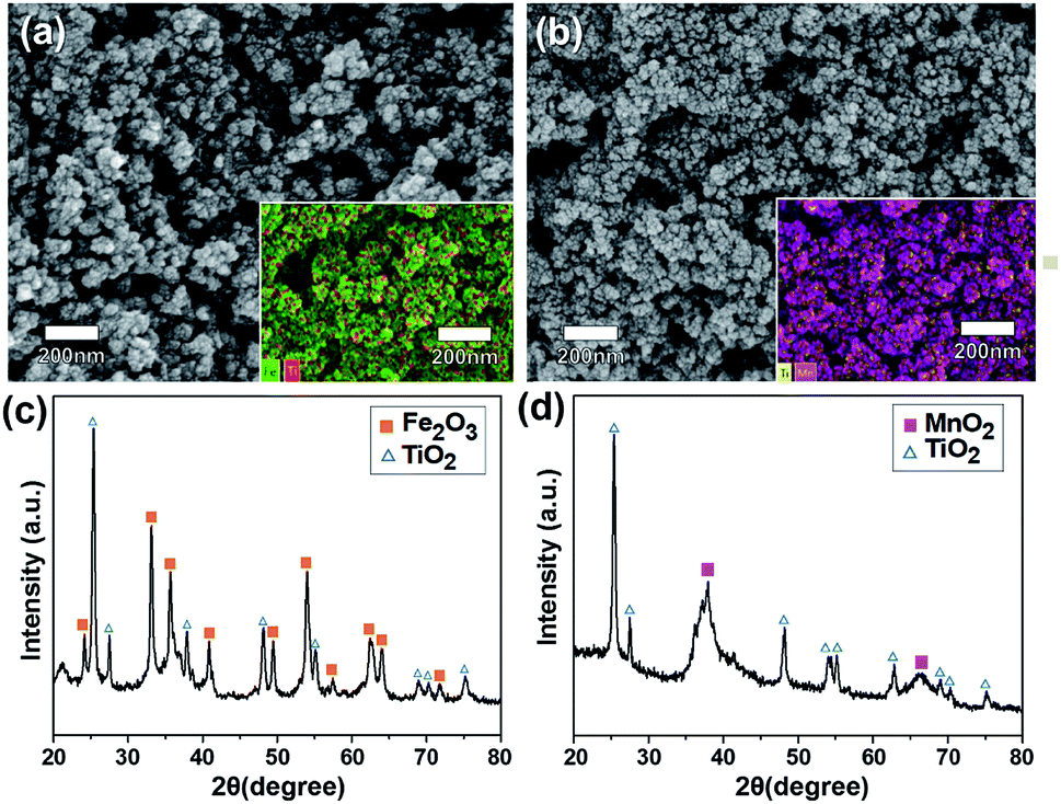
The morphologies of the TiO2-NPs-embedded Fe2O3 and MnO2 NPs were characterized by FE-SEM (Fig. 1a and b). Uniform, spherical particles with tens of nanometers in size were clearly observed. The elemental SEM-mapping results for the Ti atoms shown in the inset of the figures indicated that the TiO2 NPs were well and uniformly dispersed. The Ti/Fe and Ti/Mn atomic ratios determined from the SEM-mapping analyses were equivalent to the mole fraction of TiO2 used, indicating a stoichiometric embedment of the TiO2 NPs. The crystallinities of the TiO2–Fe2O3 and TiO2–MnO2 composite NPs were characterized by XRD measurements. While clear diffraction patterns corresponding to the hematite α-Fe2O3 phase30 for the TiO2–Fe2O3 NPs were observed (Fig. 1c), the broader peaks of the TiO2–MnO2 NPs (Fig. 1d) indicated typical amorphous characteristic of the MnO2 NPs.31–33 Additional diffraction peaks corresponding to the TiO2 anatase phase were also observed for both composite NPs. More close morphology of the synthesized TMO NPs were observed by TEM (Fig. S2†). In the case of Fe2O3 NPs, the clear lattice fringe in the TEM image and spots and rings in the selected area electron diffraction (SAED) pattern indicated the polycrystalline characteristics. In contrast, for the MnO2 NPs, the fringes and SAED spots were hardly observed, indicating relatively amorphous characteristics, consistent with the XRD results.
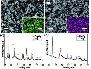 |
| | Fig. 1 FE-SEM images of (a) TiO2–Fe2O3 and (b) TiO2–MnO2 NPs, and XRD patterns of (c) TiO2–Fe2O3 and (d) TiO2–MnO2 NPs. The inset SEM-mapping images for Ti atoms in (a) and (b) show uniform dispersion of the TiO2 NPs. | |
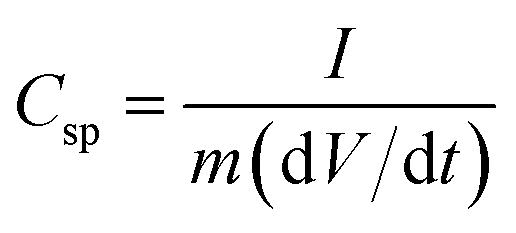
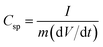
Fig. 2a shows the cyclic voltammogram (CV) measured using a three-electrode system at a scan rate of 30 mV s−1 for the Fe2O3 (negative voltage range) and MnO2 (positive voltage range) half-cell electrodes with and without TiO2 incorporation. The specific capacitance, Csp, of the electrodes was calculated by the following equation;
| |  | (1) |
where
I (A) is the average current,
m (g) is the deposit weight, and d
V/d
t (mV s
−1) is the scan rate.
34 The area of the CV contour, indicative of the specific capacitance, of the TiO
2–MnO
2 electrode is significantly larger than that of the TiO
2-free MnO
2 electrode, while the areas of the Fe
2O
3 electrode are little varied. The calculated
Csp value of the MnO
2 electrode increased from 114.0 F g
−1 to 141.5 F g
−1 after the TiO
2 incorporation. The CVs of the half-cell electrodes before and after TiO
2 incorporation measured at various scan rates are shown in Fig. S3.
† More quantitative analyses on the effect of the TiO
2 incorporation were carried out by deconvoluting the capacitive elements of the electrodes. At a given applied voltage, a current is regarded as a sum of the two capacitive elements, namely a surface element (
k1v) and faradaic insertion element (
k2v1/2), according to the following equation;
35,36where
v is the scan rate and
k1,
k2 are constants. The process of extracting elements was described elsewhere.
37
 |
| | Fig. 2 Cyclic voltammograms of the Fe2O3, TiO2–Fe2O3, MnO2, TiO2–MnO2 electrodes at a scan rate of 30 mV s−1 (a) and deconvolutions of the total capacitance into surface element (solid part) and insertion element (shaded part) for the (b) TiO2–MnO2 and (c) TiO2–Fe2O3 electrodes measured at 30 and 100 mV s−1. The bar graphs represent the contribution of each element at various scan rates. | |
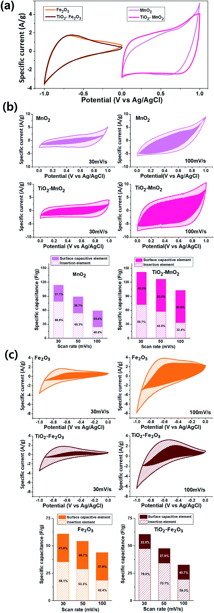
The deconvoluted CV graphs for the MnO2 electrodes at scan rates of 30 mV s−1 and 100 mV s−1 are shown in Fig. 2b. The k1v plot corresponding to the surface capacitive element is shown as a solid area, and the other shaded area corresponds to the insertion element. The surface element of the TiO2-free MnO2 electrode was approximately 34.9 F g−1, which was virtually independent of the scan rate.36 However, the insertion element decreased from 79.0 F g−1 at 30 mV s−1 to 23.8 F g−1 at 100 mV s−1 because the diffusion-controlled insertion was less accessible at a higher scan rate.38,39 The contribution of the insertion element in the total capacitance hence decreased from 69.3% at 30 mV s−1 to 40.5% at 100 mV s−1. The incorporation of the TiO2 NPs significantly increased the surface element to 69.2 F g−1. The insertion element also increased to 72.3 F g−1 at 30 mV s−1 and 33.0 F g−1 at 100 mV s−1. As a result, at 30 mV s−1, the total specific capacitance of the TiO2-incorporated MnO2 electrode (141.5 F g−1) was 1.24 times larger than that of the TiO2-free MnO2 electrode (114.0 F g−1). At a high scan rate, the effect of the TiO2 incorporation was more apparent, reaching a 1.73 times increase in Csp from 58.8 F g−1 to 102.2 F g−1 at 100 mV s−1. This enhancement in specific capacitance and voltammetric response is probably attributed to the reduced resistance of the electrode due to incorporation of electrically more conductive TiO2 NPs. The resistive elements of the electrodes was evaluated by electrochemical impedance spectroscopy (EIS) measurements (Fig. 3a and b). The diameter of the round curve in the high-frequency region of the Nyquist plots, indicative of the charge-transfer resistance, Rct, were significantly smaller for the TiO2-incorporated electrodes. The diffusive resistance, Rd, which is inversely proportional to the slope of the line in the low-frequency region, also decreased by the TiO2 incorporation.
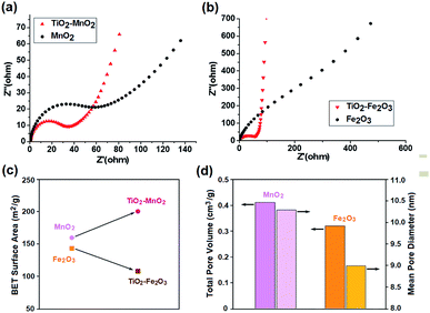 |
| | Fig. 3 Nyquist plots of (a) MnO2- and (b) Fe2O3-based electrodes, and (c) BET specific surface area and (d) total pore volume and mean pore diameter of the synthesized TMO NPs. | |
While the incorporation of the TiO2 NPs improved both the capacitive elements of the MnO2-based electrode, only the insertion element was increased in the case of the Fe2O3 electrode (Fig. 2c). The scan-rate-independent surface element of the TiO2-free Fe2O3 electrode was approximately 25.2 F g−1, while the insertion element was 35.6 F g−1 (58.1%) at 30 mV s−1 and 16.6 F g−1 (42.4%) at 100 mV s−1. For the TiO2–Fe2O3 electrode, the insertion elements were significantly larger over the whole range of the scan rate, e.g. 47.2 F g−1 (78.0%) at 30 mV s−1 and 19.3 F g−1 (59.3%) at 100 mV s−1, indicating that the incorporation of the TiO2 NPs improved the diffusion of the charge carriers in the Fe2O3 electrode. In contrast, the TiO2 incorporation decreased the surface elements from 25.2 F g−1 to 13.3 F g−1. The opposite effect of the TiO2 incorporation on the surface elements of the MnO2 and Fe2O3 electrode is probably related to the change of their surface area. The BET isotherms, with an adsorption–desorption hysteresis loop as shown in Fig. S4,† indicate that the synthesized MnO2 and Fe2O3 NPs can be categorized as a mesoporous adsorbents.40 This porous nature of the electrode materials is favourable for the application to supercapacitor electrodes due to the increased surface sites for the energy storage.41–44 While the specific surface area of the MnO2 NPs increased from 137.5 m2 g−1 to 164.3 m2 g−1 by the TiO2 incorporation, that of the Fe2O3 NPs decreased from 142.5 m2 g−1 to 107.5 m2 g−1 (Fig. 3c). Although it is not clear yet, the incorporation of TiO2 NPs on the MnO2 NPs with larger pore volume and mean pore diameter (Fig. 3d) might lead to more morphological hierarchization. On the other hand, the TiO2 incorporation on Fe2O3 NPs seemed to result in a reduction of contact sites with the electrolyte. All the deconvolution results are summarized in Tables S1 and S2.†
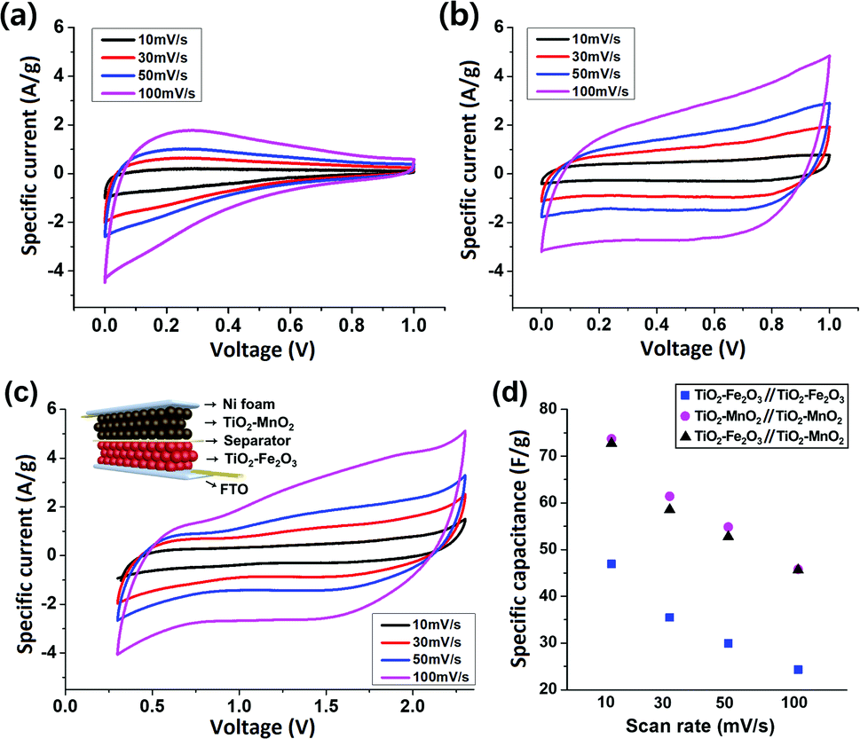
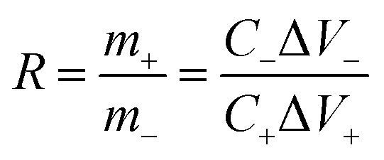
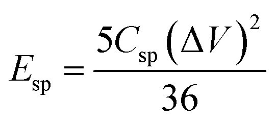
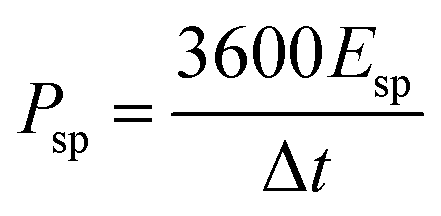
Based on the results of the two composite TMO NPs-based single electrode cells, an asymmetric full-cell consisting of TiO2–Fe2O3 and TiO2–MnO2 electrodes was fabricated. Since the electrochemical redox reactions of the two electrodes occur in entirely different voltage ranges, i.e. −1.0–0.0 V for the TiO2–Fe2O3 and 0.0–1.0 V for the TiO2–MnO2 electrode, the asymmetric combination of the two electrodes was expected to significantly increase the specific energy of the device. The schematic of the ASC device is shown in the inset of Fig. 4c. For comparison, symmetric supercapacitors, i.e. devices based on TiO2–Fe2O3‖TiO2–Fe2O3 and TiO2–MnO2‖TiO2–MnO2 electrodes, were also fabricated. Fig. 4a and b show the CV contours of the TiO2–Fe2O3 and TiO2–MnO2 symmetric cell, respectively, at various scan rates from 10 mV s−1 to 100 mV s−1. The calculated Csp values are plotted as a function of the scan rate (Fig. 4d). The Csp value of the TiO2–Fe2O3 symmetric device was 35.5 F g−1 measured at a scan rate of 30 mV s−1. This Csp value is approximately half the value of the TiO2–Fe2O3 single electrode, 60.5 F g−1, according to the following equation for the Csp calculation of symmetric or asymmetric devices,
| |  | (3) |
where
m is the mass,
C is the specific capacitance, and + or − denotes the values for positive and negative electrodes, respectively. The
Csp value gradually decreased as the scan rate increased, and reached 24.3 F g
−1 at 100 mV s
−1. For the TiO
2–MnO
2 symmetric device, the
Csp decreased from 73.7 F g
−1 at 10 mV s
−1 to 45.8 F g
−1 at 100 mV s
−1. The
Csp values of the symmetric cells at various scan rates are plotted in
Fig. 4d and summarized in Table S3.
†
 |
| | Fig. 4 Cyclic voltammograms of (a) TiO2–Fe2O3‖TiO2–Fe2O3 symmetric, (b) TiO2–MnO2‖TiO2–MnO2 symmetric and (c) TiO2–Fe2O3‖TiO2–MnO2 asymmetric devices at various scan rates. The inset in (c) represents the schematic of the asymmetric device structure. The Csp values of the devices are plotted as a function of the scan rate in (d). | |
Prior to the assembly of the TiO2–Fe2O3‖TiO2–MnO2 ASCs, the mass ratio of the TiO2–Fe2O3 and TiO2–MnO2 NPs was determined by the Csp values of the Fe2O3- and MnO2-based symmetric cells using the following equation in order to make each electrode contribute equivalent capacitance,
| |  | (4) |
where Δ
V+ and Δ
V− are the voltage windows of the positive and negative electrode, respectively. The measured mass of the TiO
2–Fe
2O
3 and TiO
2–MnO
2 NPs used in this work were 3.5 and 0.8 mg cm
−2, respectively. The CVs of the TiO
2–Fe
2O
3‖TiO
2–MnO
2 ASC measured at various scan rates are shown in
Fig. 4c, and the calculated
Csp values are plotted in
Fig. 4d. A working voltage window of 2.0 V was determined by the results of the individual electrode. The
Csp values of the ASC were slightly smaller than the values of the TiO
2–MnO
2-based symmetric cell over the entire range of the scan rates. The largest
Csp value of 72.7 F g
−1 was obtained at a scan rate of 10 mV s
−1, and the value decreased to 45.6 F g
−1 at 100 mV s
−1. This scan rate retention of 62.7% was larger than 51.8% for the TiO
2–Fe
2O
3 symmetric cell and 62.1% for the TiO
2–MnO
2 symmetric cell, as shown in
Fig. 4d, indicating a higher voltammetric response of the ASC.
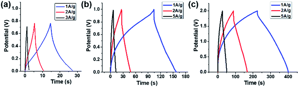
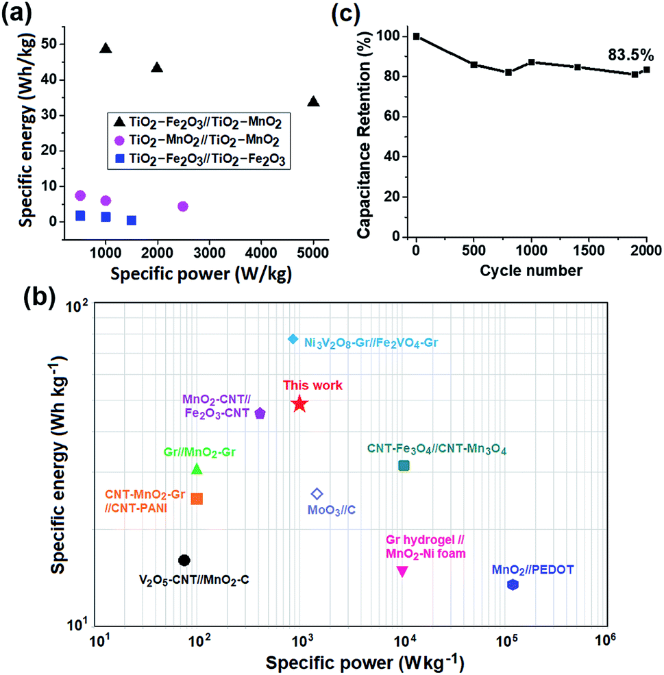
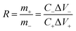
The capacitive performance of the Fe2O3- and MnO2-based symmetric and asymmetric cells were also estimated by galvanostatic charge–discharge (GCD) measurements shown in Fig. 5. The Csp value of the TiO2–Fe2O3 symmetric cell was 12.8, 10.3, and 3.5 F g−1 measured at a current density of 1, 2 and 3 A g−1, respectively (Fig. 5a). The considerably extended discharge time of the TiO2–MnO2 symmetric and asymmetric cells (Fig. 5b and c) indicate the better capacitance of the MnO2-based electrode. The calculated Csp values of the TiO2–Fe2O3‖TiO2–MnO2 ASC were 87.5, 77.7, and 33.6 F g−1 at a current density of 1, 2 and 5 A g−1, respectively. The obtained Csp values at various current densities are summarized in Table S4.† In addition to the larger Csp value of the TiO2–Fe2O3‖TiO2–MnO2 ASC, the doubly extended voltage window contributed to the enhancement in the energy density of the device shown in the Ragone plots (Fig. 6a). The specific energy (Esp) and specific power (Psp) of the cells were calculated using the following equations,45,46
| |  | (5) |
| |  | (6) |
where Δ
V (V) is the applied voltage window and Δ
t (s) is the discharge time. As shown in the figure, the specific energies of the TiO
2–Fe
2O
3‖TiO
2–MnO
2 ASC are larger than those of the symmetric cells at the given specific power. The specific energy of the TiO
2–Fe
2O
3‖TiO
2–MnO
2 ASC reached 48.6 W h kg
−1 at a specific power of 1000 W kg
−1. The
Esp values of the all-metal-oxide-NPs-based symmetric and asymmetric supercapacitors are summarized in
Table 1. The obtained specific energy of the TiO
2–Fe
2O
3‖TiO
2–MnO
2 ASC is comparable to the metal oxide electrode-based ASCs reported in the literature, including CNT-Fe
3O
4‖CNT-Mn
3O
4,
47 graphene (Gr) hydrogel‖MnO
2–Ni foam,
10 Gr‖MnO
2-Gr,
48 MnO
2-CNT‖Fe
2O
3-CNT,
49 CNT-MnO
2-Gr‖CNT-PANI,
50 V
2O
5-CNT‖MnO
2–C,
51 Ni
3V
2O
8-Gr‖Fe
2VO
4-Gr,
52 MnO
2‖PEDOT
53 and MoO
3‖C
54 ASCs, as shown in
Fig. 6b. The cycle stability of the TiO
2–Fe
2O
3‖TiO
2–MnO
2 ASC was also evaluated by repetitive GCD measurement cycles at a specific current of 2 A g
−1 (
Fig. 6c). The
Csp retention after 2000 GCD cycles was 83.5% of the initial value. The apparent change in the surface morphology of the electrodes was not observed after 2000 GCD cycles (Fig. S5
†), also indicating the good structural stability of the TiO
2–Fe
2O
3‖TiO
2–MnO
2 ASC electrodes.
 |
| | Fig. 5 (a) Galvanostatic charge–discharge curves of (a) TiO2–Fe2O3‖TiO2–Fe2O3 symmetric, (b) TiO2–MnO2‖TiO2–MnO2 symmetric and (c) TiO2–Fe2O3‖TiO2–MnO2 asymmetric devices at various specific currents. | |
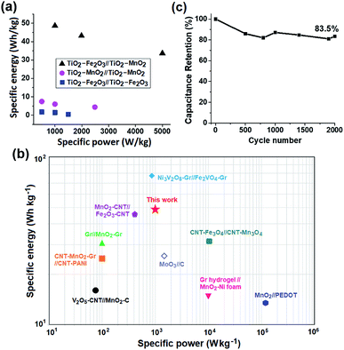 |
| | Fig. 6 Ragone plots for (a) Fe2O3- and MnO2-based devices and (b) other ASCs reported in the literature for comparison, and (c) capacitance retention of the TiO2–Fe2O3‖TiO2–MnO2 ASC as a function of the number of GCD cycles at a specific current of 2 A g−1. | |
Table 1 Summary of the capacitive properties of the TiO2–Fe2O3 and TiO2–MnO2 NPs-based symmetric and asymmetric devices
| Capacitive properties |
TiO2–Fe2O3‖TiO2–Fe2O3 symmetric |
TiO2–MnO2‖TiO2–MnO2 symmetric |
TiO2–Fe2O3‖TiO2–MnO2 asymmetric |
|
C
sp measured at 10 mV s−1 (F g−1) |
46.9 |
73.7 |
72.7 |
| Voltammetric retention |
51.8% |
62.1% |
62.7% |
|
E
sp at Psp of 1000 W kg−1 (W h kg−1) |
1.4 |
6.0 |
48.6 |
Conclusions
An all-metal-oxide-NPs-based ASC with electrodes made of TiO2 NPs-incorporated Fe2O3 and MnO2 NPS was successfully fabricated. In the MnO2 NPs-based single electrode, the incorporation of the TiO2 NPs improved the specific capacitance from 114.0 F g−1 to 141.5 F g−1 at a scan rate of 30 mV s−1. The deconvolution of the capacitive elements indicated that this enhancement was attributed to an increase in both the surface element and insertion element. However, for the Fe2O3 NPs-based electrode, the insertion element was increased while the surface capacitive element was reduced so that the total capacitance did not improve apparently. An ASC comprised of these two composite TMO electrodes, the TiO2–Fe2O3 and TiO2–MnO2 electrodes, was fabricated. The Csp value of the TiO2–Fe2O3‖TiO2–MnO2 ASC reached 72.7 F g−1 measured at a scan rate of 10 mV s−1, which is slightly lower than the value for the TiO2–MnO2‖TiO2–MnO2 (73.7 F g−1) symmetric capacitors. However, the ASC could operate over a voltage window of 2.0 V, twice as large as that of the symmetric devices, which resulted in a significant enhancement in the specific energy of the device. The specific energy of the TiO2–Fe2O3‖TiO2–MnO2 ASC was 48.6 W h kg−1 at a specific power of 1000 W kg−1 while that of the TiO2–Fe2O3‖TiO2–Fe2O3 and TiO2–MnO2‖TiO2–MnO2 symmetric capacitor was 1.4 and 6.0 W h kg−1, respectively. The Csp retention of the TiO2–Fe2O3‖TiO2–MnO2 ASC was approximately 83.5% of the initial value after 2000 GCD cycles. All the benefits, i.e. wide operating voltage window and comparable specific capacitance, demonstrate that an all-metal-oxide-NPs-based ASC is a promising architecture for high energy density supercapacitors. It also implies that the device performance will be further improved by optimizing the type and composition of the TMO NPs used.
Conflicts of interest
There is no conflicts to declare.
Acknowledgements
This work was supported by National Research Foundation of Korea (NRF) Grant (No. 2016R1A5A1012966 and 2017R1A2B4012375) funded by the Korean Government.
Notes and references
- J. Wang, S. Y. Dong, B. Ding, Y. Wang, X. D. Hao, H. Dou, Y. Y. Xia and X. G. Zhang, Natl. Sci. Rev., 2017, 4, 71 CAS.
- J. Yan, Q. Wang, T. Wei and Z. Fan, Adv. Energy Mater., 2014, 4, 1300816 CrossRef.
- J. D. Liu and S. B. Lee, Chem. Commun., 2011, 47, 1384 RSC.
- L. L. Zhang and X. S. Zhao, Chem. Soc. Rev., 2009, 38, 2520 RSC.
- K. Zhang, X. Han, Z. Hu, X. Zhang, Z. Tao and J. Chen, Chem. Soc. Rev., 2015, 44, 699 RSC.
- C. Yang, M. Sun and H. Lu, Chem.–Eur. J., 2018, 24, 6169 CrossRef CAS.
- P. Sennu, V. Aravindan and Y. S. Lee, J. Power Sources, 2016, 306, 248 CrossRef CAS.
- L. Demarconnay, E. Raymundo-Piñero and F. Béguin, J. Power Sources, 2011, 196, 580 CrossRef CAS.
- J. Yan, Z. Fan, W. Sun, G. Ning, T. Wei, Q. Zhang, R. Zhang, L. Zhi and F. Wei, Adv. Funct. Mater., 2012, 22, 2632 CrossRef CAS.
- H. Gao, F. Xiao, C. B. Ching and H. Duan, ACS Appl. Mater. Interfaces, 2012, 4, 2801 CrossRef CAS.
- T. Cottineau, M. Toupin, T. Delahaye, T. Brousse and D. Bélandger, Appl. Phys. A, 2006, 82, 599 CrossRef CAS.
- S. T. Senthilkumar, R. K. Selvan, M. Ulaganathan and J. S. Melo, Electrochim. Acta, 2014, 115, 518 CrossRef CAS.
- S. W. Zhang, B. S. Yin, c. Liu, Z. B. Wang and D. M. Gu, Appl. Surf. Sci., 2018, 458, 478 CrossRef CAS.
- M. Toupin, T. Brousse and D. Bélanger, Chem. Mater., 2004, 16, 3184 CrossRef CAS.
- I. Ryu, G. Kim, H. Yoon, S. J. Ahn and S. Yim, RSC Adv., 2016, 6, 102814 RSC.
- G. Kim, I. Ryu and S. Yim, Sci. Rep., 2017, 7, 8260 CrossRef.
- R. S. Kate, S. A. Khalate and R. J. Deokate, J. Alloys Compd., 2018, 734, 89 CrossRef CAS.
- Z. Yu, L. Tetard, L. Zhai and J. Thomas, Energy Environ. Sci., 2015, 8, 702 RSC.
- D. Hong and S. Yim, RuO2, Langmuir, 2018, 34, 4249 CrossRef CAS PubMed.
- Y. Liu, D. Luo, K. Shi, X. Michaud and I. Zhitomirsky, Nano-Struct. Nano-Objects, 2018, 15, 98 CrossRef CAS.
- G. S. Gund, D. P. Dubal, N. R. Chodankar, J. Y. Cho, P. Gomez-Romero, C. Park and C. D. Lokhande, Sci. Rep., 2015, 5, 12454 CrossRef.
- Z. Liu, X. Tian, X. Xu, L. He, M. Yan, C. Han, Y. Li, W. Yang and L. Mai, Nano Res., 2017, 10, 2471 CrossRef CAS.
- S. C. Pang, M. A. Anderson and T. W. Chapman, J. Electrochem. Soc., 2000, 147, 444 CrossRef CAS.
- Y. Hu, C. Guan, Q. Ke, Z. F. Yow, C. Cheng and J. Wang, Chem. Mater., 2016, 28, 7296 CrossRef CAS.
- A. A. Yadav, J. Mater. Sci.: Mater. Electron., 2016, 27, 12876 CrossRef CAS.
- P. Y. Tang, L. J. Han, A. Genc, Y. M. He, X. Zhang, L. Zhang, J. R. Galán-Mascarós, J. R. Morante and J. Arbiol, Nano Energy, 2016, 22, 189 CrossRef CAS.
- S. Ito, Y. Yui and J. Mizuguchi, Mater. Trans., 2010, 51, 1163 CrossRef CAS.
- X. Lu, M. Yu, G. Wang, T. Zhai, S. Xie, Y. Ling, Y. Tong and Y. Li, Adv. Mater., 2013, 25, 267 CrossRef CAS.
- G. Kim, J. Kang, G. Choe and S. Yim, Int. J. Electrochem. Sci., 2017, 12, 10015 CrossRef CAS.
- A. Lassoued, B. Dkhil, A. Gadri and S. Ammar, Results Phys., 2017, 7, 3007 CrossRef.
- S. Li, L. Qi, L. Lu and H. Wang, RSC Adv., 2012, 2, 3298 RSC.
- H. Xingkang, L. Dongping, Y. Hongjun, A. Adel and Y. Yong, Nanotechnology, 2008, 19, 225606 CrossRef PubMed.
- A. Zolfaghari, F. Ataherian, M. Ghaemi and A. Gholami, Electrochim. Acta, 2007, 52, 2806 CrossRef CAS.
- C. D. Lokhande, D. P. Dubal and O.-S. Joo, Curr. Appl. Phys., 2011, 11, 255 CrossRef.
- T.-C. Liu, W. G. Pell, B. E. Conway and S. L. Roberson, J. Electrochem. Soc., 1998, 145, 1882 CrossRef CAS.
- J. Wang, J. Polleux, J. Lim and B. Dunn, J. Phys. Chem. C, 2007, 111, 14925 CrossRef CAS.
- I. Ryu, G. Kim, D. Park and S. Yim, J. Power Sources, 2015, 297, 98 CrossRef CAS.
- W. Yan, T. Ayvazian, J. Kim, Y. Liu, K. C. Donavan, W. Xing, Y. Yang, J. C. Hemminger and R. M. Penner, ACS Nano, 2011, 5, 8275 CrossRef CAS PubMed.
- J. Duay, S. A. Sherrill, Z. Gui, E. Gillette and S. B. Lee, ACS Nano, 2013, 7, 1200 CrossRef CAS.
- K. S. W. Sing, D. H. Everett, R. A. W. Haul, L. Moscou, R. A. Pierotti, J. Rouquerol and T. Siemieniewska, Pure Appl. Chem., 1985, 570, 603 Search PubMed.
- J. Cherusseri, K. S. Kumar, N. Choudhary, N. Nagaiah, Y. Jung, T. Roy and J. Thomas, Nanotechnology, 2019, 30, 202001 CrossRef CAS.
- D. Wang, Y. Xiao, X. Luo, Z. Wu, Y.-J. Wang and B. Fang, ACS Sustainable Chem. Eng., 2017, 5, 2509 CrossRef CAS.
- Y.-Z. Wei, B. Fang, S. Iwasa and M. Kumagai, J. Power Sources, 2005, 141, 386 CrossRef CAS.
- B. Fang, J. H. Kim, M.-S. Kim, A. Bonakdarpour, A. Lam, D. P. Wilkinson and J.-S. Yu, J. Mater. Chem., 2012, 22, 19031 RSC.
- V. Khomenko, E. Raymundo-Piñero and F. Béguin, J. Power Sources, 2006, 153, 183 CrossRef CAS.
- T. Brousse, P.-L. Taberna, O. Crosnier, R. Dugas, P. Guillemet, Y. Scudeller, Y. Zhou, F. Favier, D. Bélanger and P. Simon, J. Power Sources, 2007, 173, 633 CrossRef CAS.
- A. Kumar, D. Sarkar, S. Mukherjee, S. Patil, D. D. Sarma and A. Shukla, ACS Appl. Mater. Interfaces, 2018, 10, 42484 CrossRef CAS.
- Z.-S. Wu, W. Ren, D.-W. Wang, F. Li, B. Liu and H.-M. Cheng, ACS Nano, 2010, 4, 5835 CrossRef CAS.
- T. Gu and B. Wei, J. Mater. Chem. A, 2016, 4, 12289 RSC.
- Y. Jin, H. Chen, M. Chen, N. Liu and Q. Li, ACS Appl. Mater. Interfaces, 2013, 5, 3408 CrossRef CAS.
- Z. Chen, Y. Qin, D. Weng, Q. Xiao, Y. Peng, X. Wang, H. Li, F. Wei and Y. Lu, Adv. Funct. Mater., 2009, 19, 3420 CrossRef CAS.
- M. Guo, J. Balamurugan, N. H. Kim and J. H. Lee, Appl. Catal., B, 2018, 239, 290 CrossRef CAS.
- V. Khomenko, E. Raymundo-Pinero, E. Frackowiak and F. Beguin, Appl. Phys. A, 2006, 82, 567 CrossRef CAS.
- L. Wang, L. Gao, J. Wang and Y. Shen, J. Mater. Sci., 2019, 54, 13685 CrossRef CAS.
Footnote |
| † Electronic supplementary information (ESI) available: SEM image of TiO2-free Fe2O3 and MnO2 electrodes, TEM images of the TMO electrodes, CVs of TMO electrodes, BET N2 adsorption–desorption isotherm plots of TMO NPs, FE-SEM images of the electrodes taken before and after the GCD cycle test, summary of deconvolution results of capacitive elements of the TMO-based electrodes, summary of specific capacitances of TMO-based electrodes. See DOI: 10.1039/c9ra06066a |
|
| This journal is © The Royal Society of Chemistry 2019 |
Click here to see how this site uses Cookies. View our privacy policy here. 
 Open Access Article
 This Open Access Article is licensed under a Creative Commons Attribution-Non Commercial 3.0 Unported Licence
 *
*