 Open Access Article
In situ generation of sustainable PLA-based nanocomposites by shear induced crystallization of nanofibrillar inclusions†
Ramin
Hosseinnezhad
a,
Iurii
Vozniak
*a,
Jerzy
Morawiec
a,
Andrzej
Galeski
 *a and
Slawomir
Dutkiewicz
b
aCentre of Molecular and Macromolecular Studies, Polish Academy of Sciences, 90-363 Lodz, Poland. E-mail: wozniak@cbmm.lodz.pl; andgal@cbmm.lodz.pl
bInstitute of Biopolymers and Chemical Fibers, 90-570 Lodz, Poland
First published on 25th September 2019
Abstract
In situ formation of polymer nanofibrils during compounding with a second polymer followed by their immediate solidification due to shear induced crystallization for two pairs of polymers is described. Sustainable green biopolymer–biopolymer nanocomposites of polylactide (PLA) were then fabricated based on two copolyesters forming nanofibrils during shearing: poly(butylene adipate-co-succinate-co-glutarate-co-terephthalate) (PBASGT) and poly(butylene adipate-co-terephthalate) (PBAT). The shear induced crystallization allowed solidification of PBASGT or PBAT nanofibers immediately under applying a high shear rate without subsequent cooling. The melt memory unveiling as a self-nucleation facilitated shear-induced crystallization. Formation of nanofibril-matrix morphology led to an exceptional combination of strength, modulus and ductility. In situ SEM observation of the tensile test revealed crazing as a dominant mechanism for PLA deformation. However, addition of PBASGT or PBAT resulted in intensified crazing followed by shear banding. Increase of PBASGT or PBAT concentration promoted the brittle-to-ductile transition of the PLA matrix. At the same time, PBAT or PBASGT nanofibers span PLA craze surfaces and at large strain, when PLA craze tufts get broken, they bridge the craze gaps resulting in an increase of both strength and plasticity of PLA.
1. Introduction
With fast growing awareness of environmental issues, the demand for plastics is being shifted from conventional materials to renewable and natural biopolymers.1,2 Two different approaches are often employed for the production of these green polymers. The first is blending of two biopolymers with or without using natural plasticizers or compatibilizers as a third component.3,4 Such low molecular weight additives improve minor phase dispersion and adhesion of phases. However, they may leach out of the biopolymer blend resulting in deterioration of properties over time. The second approach deals with adding natural polymers in the form of fibers or particles into the biopolymer matrix. In this case, controlling the level of dispersion is still the main challenge.5,6 It is also possible to significantly improve the mechanical performance of biopolymers by incorporating different inorganic nanoparticles or petroleum thermoplastic, but it is necessary to minimize the concentration of the dispersed phase in order to save green nature and recyclability of the polymer matrix.7,8Since biopolymer fibers lack drawbacks such as poor moisture resistance and poor thermal stability, they can be an alternative to natural fibers for reinforcing biocomposites. Recently, in situ transformation of biopolymer blends into micro- or nanofibrillar biocomposites in which higher melting point biopolymer acts as reinforcement in the form of the fibers and lower melting point biopolymer acts as a matrix has shown great potential towards improving properties of biopolymers. Compared to ready-made polymer fibers, in situ generated polymer fibers demonstrate an excellent level of dispersion. Furthermore, the in situ fibrillated polymer is characterized by higher specific interfacial area than droplet dispersed polymer. Thus, it can form the physical network structure which more significantly enhances stress transfer between the matrix and the dispersed phase.9–11
The in situ fibrillation of polymeric blends is usually produced by three main processing steps.12 First, conventional melt blending of polymers which is later followed by cold/hot stretching. This transforms both phases into highly oriented fibrils. In the third step the fibrillated blend is further processed at temperature above the melting point of matrix, but below the melting point of minority phase. This leads to isotropic polymer matrix with randomly oriented fibrils of the dispersed phase. Formation of such physical network structure is challenged for composites with a high concentration of minor phase.8 Micro-injection moulding is an alternative method when the formation of stable fibrillation morphology is achieved by imposing a high stretching deformation in the feeding system. Since it requires high shear rates (for instance 105 s−1), the process is hardly realized in the course of conventional injection moulding.13 In another extrusion technique, both polymers first get melted close to the feeding zone. Later at zones near the die, the minor phase will be solidified to fibrous dispersion under a flow field while the matrix is still in molten state. However, only isotactic-PP/HDPE blends were obtained in this way.14,15 Recently a new approach was proposed by us based on simultaneous orientation and crystallization of polymer fibers directly in the stage of extrusion, no need for additional annealing. By applying high shear rates to induce crystallization at higher temperatures, the fibers are solidified without a succeeding cooling below its nonisothermal crystallization temperature. Meanwhile, the matrix remains in a viscous state and its solidification is accompanied by the formation of randomly oriented nanofibers. Such an approach has been used only for PLA reinforced with highly oriented fibers of PBS.10
Our current study focuses on new PLA-based blends namely PLA with novel aliphatic-aromatic copolyesters (PBASGT), synthesized previously,16 and commercial PBAT. It is attempted to transform the blends to composites by morphology modification in the minor phase from droplets to fibers. PBASGT or PBAT is crystallizable just under high shear rates and its crystals melt at temperature higher than the softening temperature of PLA. In this work, we propose a slit die extrusion process for modification of PLA matrix by formation of the shear band transformation as well as the PBASGT or PBAT nanofibers that aside from strengthening act as effective spanning PLA craze surfaces reinforcement. Further tests were carried out to perceive the plastic deformation mechanisms responsible for the registered transition from brittle fracture to plastic flow (i.e. brittle-to-ductile transition) under varied concentration and morphology of the minor polymer phase (droplets or fibers).
2. Experimental section
2.1 Materials
Commercial grade of PLA 4060D, supplied by NatureWorks LLC, with a density of 1.24 g cm−3, Mw of 120![[thin space (1/6-em)]](https://www.rsc.org/images/entities/char_2009.gif) 000 g mol−1, and 18 mol% of D-lactide content was used as the matrix. Poly(butylene adipate-co-terephthalate) (PBAT) with the trade name Ecoflex type F Blend C1200 was chosen along with PBASGT, an aliphatic-butylene terephthalate copolyester synthesized and described by us earlier,17 in order to reinforce the PLA.
000 g mol−1, and 18 mol% of D-lactide content was used as the matrix. Poly(butylene adipate-co-terephthalate) (PBAT) with the trade name Ecoflex type F Blend C1200 was chosen along with PBASGT, an aliphatic-butylene terephthalate copolyester synthesized and described by us earlier,17 in order to reinforce the PLA.
2.2 Sample preparation
3, 6, and 10 wt% of copolyesters were blended with PLA (all dried for 8 h at 60 °C) following the procedure reported earlier.10 Temperature zones of twin-screw extruder were set increasingly from 160 °C to 190 °C, while this temperature gradient descended for single-screw extruder from 175 °C (feed section) to 125 °C (slit die).2.3 Mechanical and thermal properties
Tensile properties of composites, blends and neat PLA were measured in Instron-5582 (Universal Testing Machine) at a strain rate of 5% min−1 according to ISO 527-2. Specimens of the gauge length of 25 mm and the width of 5 mm (ISO 527-2, type 1BA) were cut out from the compression molded films and from extruded tapes using a steel template. For extrudates, specimens oriented along the extrusion directions were prepared. Impact strength was determined in Resil-5.5 (Instrumented Impact Tester) as per ISO 8256. Specimens with gage length of 25 mm and width of 3 mm were struck by the hammer with the speed of 2.9 m s−1 and energy of 1 J. Seven specimens were tested for each sample at room temperature. Rectangular samples with dimensions of 24 × 10 × 0.75 mm3 were tested for dynamic mechanical thermal analysis (DMTA) using DMA Q800 (TA Instruments) at heating rate of 2 °C min−1. Melting and crystallization kinetics were probed with DSC 2920 (TA Instruments) under nitrogen purging condition (20 ml min−1). Samples of the 7–8 mg mass were cut out from PLA, blends, and composites and crimped in standard Al pans. The measurements were carried out by heating and subsequent cooling of samples with the rate of 10 °C min−1.2.4 Scanning electronic microscopy (SEM)
Prior to investigating the morphology of cryogenic fractures with JEOL JSM-5500 LV scanning electron microscope, PLA was selectively etched for a week utilizing the solution proposed by He et al.18 The surfaces of samples were coated with gold. Gatan MT200 (Microtest Tensile Stage), connected to the microscope, facilitated in situ observations of tensile test according to ASTM D638. Specimens were coated with carbon and deformed with the rate 0.2 mm min−1 following the procedure described earlier.102.5 Rheo-optical measurements: shear-induced crystallization test
Shear-induced crystallization of copolyesters was scrutinized in the Linkam CSS450 (Optical Shearing System) as per Bojda et al.19 PBASGT and PBAT films were positioned between two heated glass stages undergoing subsequent treatment under a nitrogen flow: (1) heating to 60 °C above melting point at (30 °C min−1), (2) holding for 5 min to eliminate possibly orientation of chains, (3) cooling down with simultaneous shearing at rates 100–600 s−1.The crystallization was monitored with a polarized light microscope Nikon Eclipse 80i and recorded by a Nikon DS-Fi1 video camera. To follow the conversion of melt into the crystalline phase the intensity of transmitted depolarized light, denoted I, was measured. The conversion degree, α(T), was calculated according to the equation:
| α(T) = (I(T) − I0)/(Ie − I0) |
3. Results and discussion
3.1 Morphology characterization
Fig. 1 presents the shearing rate dependencies of the conversion degree of PBAT and PBASGT. It is seen that without shear (ϒ = 0 s−1), the crystallization temperature Tc determined as the half-temperature, at which conversion degree reaches 50%, is 115 °C for PBASGT and 56 °C for PBAT. Increasing the shearing rate leads to a gradual shift in the crystallization temperature of PBASGT and PBAT towards higher temperatures and a reduction in the temperature range ΔT in which the transition from molten state to crystallized one occurs. The maximum effect is achieved at ϒ = 300 s−1. In this case, Tc is 140 °C for PBASGT and 86 °C for PBAT. ΔT decreases from 22 °C to 15 °C and from 33 °C to 24 °C for PBASGT and PBAT respectively.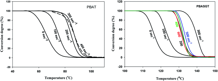 | ||
| Fig. 1 Dependencies of conversion degree of PBAT and PBASGT during cooling with simultaneous shearing with various shearing rates. | ||
However, insufficient melt flow strength and non-laminar flow due to Taylor vortices was a hindrance to reach more elevated Tc at higher shear rates (400–600 s−1). Thus, it can be assumed that the processing temperature can be higher than the nonisothermal crystallization temperature of polymer inclusions and in situ generated PBAT or PBASGT fibers would crystallize immediately under high shear rate without the need for cooling below the temperature of their quiescent crystallization. This would minimize the relaxation processes in the in situ generated polymer fibers and maintain the achieved degree of elongation of droplet inclusions into fibers.
Microstructures of PLA/PBASGT blends and in situ generated nanocomposites are presented in Fig. 2. As thermodynamically incompatible systems, the PLA/PBASGT blends reveal a typical two-phase structure incorporated with nanosized PBASGT particles (Fig. 2a–c). Discrete droplets of the PBASGT phase are dispersed in the PLA matrix without obvious interfacial bonding. At the same time, the particle size increases with increasing content of the PBASGT copolyester; the volume average particle size is 0.30, 0.54 and 0.72 μm for the blends with 3, 6 and 10 wt% of PBASGT, respectively. For immiscible blends, the size of the dispersed phase is generally characterized by the micrometer order, either for synthetic or biodegradable blends. Formation of a nanosized PBASGT phase in PLA blends is an evidence that the intensive shear rate (screw speed was 120 rpm) is realized in the course of blending that results in large deformation and fracture of the PBASGT phase and minimized agglomeration of the shear-split PBASGT phase.
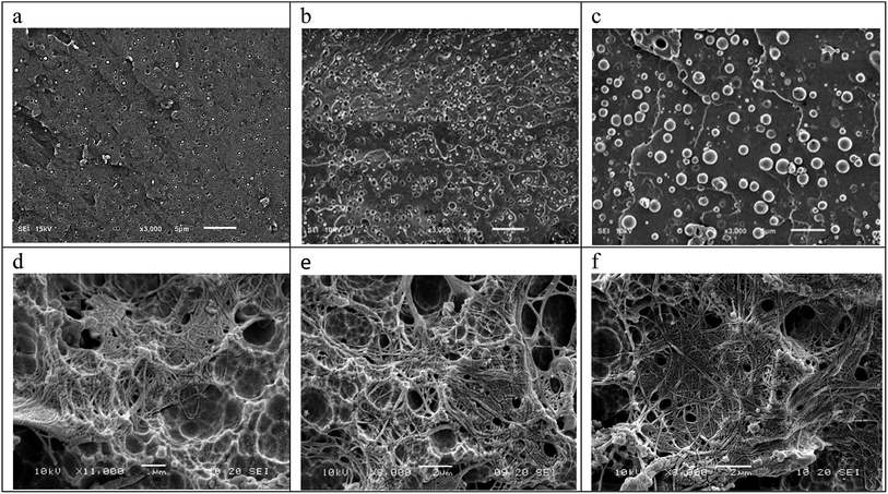 | ||
| Fig. 2 SEM images of cryofracture surfaces of PLA/PBASGT blends (a–c) and composites (d–f). (a and d) PLA/PBASGT (97/3), (b and e) PLA/PBASGT (94/6), and (c and f) PLA/PBASGT (90/10). | ||
In contrast, SEM micrographs of the in situ generated PLA/PBASGT composites reveal the presence of a fibril/matrix morphology (Fig. 2d–f). Long PBASGT nanofibers are generated that are characterized by large aspect ratios. The nanofibers are of 30–50, 50–70 and 50–100 nm in diameter at 3, 6 and 10 wt% of PBASGT, respectively. One can assume that prior to the entry of the extruder, the dispersed phase in the extruded melt is present predominantly in the form of nano-droplets. One can suggest that smaller droplets can collide, and also coalesce into larger droplets to be transformed into fibrils. Apparently nanofibrils are formed within the area between the extruder screw and the extruder walls, because they are entangled. Entanglement can occur during compounding and not during extensional flow in the slit capillary. Probably the nanofibrils are crystallized at least partially during compounding, so the fibrillar form was fixed. The slot capillary serves as a dumping for the flow and to increase the residence time of the mixture in the extruder.
The dispersed PBASGT fibrils show tight contact with the PLA matrix leaving no distinct voids between the elongated fibers and the matrix. This fact indicates a good adhesion between the fibrils and the matrix. One can note that for blends, a part of the dispersed PBASGT particles are pulled out from the PLA matrix during the fracture, leaving holes on the observation surface indicating a low adhesion between the PLA matrix and the PBASGT dispersed phase.
In the case of the PLA/PBAT blend, the phase separated structure with distinct PBAT particles embedded in PLA matrix is also observed (shown in ESI†). Finer morphology of PLA–PBAT blends/composites as compared to PLA/PBASGT blends/composites can be explained by higher compatibility between PLA and PBAT due to lower interfacial tension of the PLA–PBAT blends resulting from lower aromatic content (43.2%) than PBASGT (62.7%).20
3.2 Mechanical performance
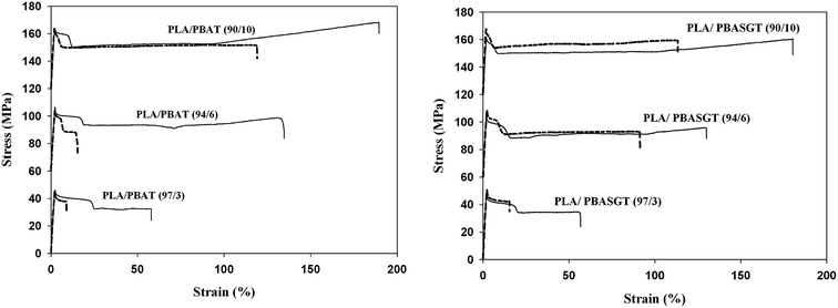
The microstructure observation for blends as well as the nanocomposites is in agreement with the analysis and results of the mechanical tests. The significant improvement in mechanical properties can be attributed to two main factors including uniform dispersion of the nanofiller and effective load transfer between the nanofiller and the PLA matrix. Here the key role in enhancement of the mechanical properties is played by the nanofiller morphology (nanodroplets vs. nanofibers) and the ability of nanofibers to form a net of physical entanglements.Examples of the respective stress–strain dependencies registered during uniaxial tensile tests of neat PLA, PLA/PBAT and PLA/PBASGT blends as well as in situ generated PLA/PBAT and PLA/PBASGT composites are shown in Fig. 3. In the neat amorphous PLA, brittle fracture is observed in the apparent elastic region, below the macroscopic yield stress.10 Addition of flexible biopolymers such as PBAT and PBASGT results in achievement of macroscopic yield stress as well as neck formation after yielding. The magnitude of the effects is determined by the concentration and the morphology of the minor polymer phase. For polymer blends, an increase in the concentration of the dispersed phase (for both PBAT and PBASGT) results in typical modification of elasticity, strength and plasticity (Tables 1 and 2). Since the Young modulus and the stress at break of PBAT and PBASGT are lower than the corresponding values of PLA, their introduction into the PLA matrix causes deterioration in its strength parameters. The formation of low adhesion between the PLA matrix and the dispersed phases also contributes to this. In PBAT based blends, Young modulus is reduced from 1.80 GPa to 1.68 GPa, and 1.64 GPa as the filler content is increased from 3 wt% to 6 wt% and 10 wt%, respectively.
| Material | Young modulus (GPa) | Yield stress (MPa) | Stress at break (MPa) | Strain at break (%) | Tensile impact strength (kJ m−2) |
|---|---|---|---|---|---|
| a Neat PLA: E = 2.04 + 0.09 GPa, σb = 43.0 ± 1.7 MPa, eb = 7.0 ± 1.0%, α = 58.9 ± 4.9 kJ m−2. | |||||
| Blend (97/3) | 1.92 ± 0.10 | 48.0 ± 1.4 | 41.5 ± 1.4 | 15.5 ± 1.1 | 61.3 + 2.1 |
| Blend (94/6) | 1.77 ± 0.12 | 47.2 ± 1.3 | 32.0 ± 0.6 | 74.7 ± 12.4 | 68.0 + 5.1 |
| Blend (90/10) | 1.70 ± 0.10 | 47.3 ± 1.7 | 34.1 ± 1.5 | 109.8 ± 26.0 | 96.8 + 15.9 |
| Composite (97/3) | 2.17 ± 0.10 | 46.2 ± 2.9 | 34.7 ± 5.4 | 67.3 ± 31.2 | 89.1 + 8.1 |
| Composite (94/6) | 2.30 ± 0.11 | 46.6 ± 1.6 | 42.8 ± 5.3 | 154.5 ± 17.4 | 96.0 + 7.8 |
| Composite (90/10) | 2.32 ± 0.14 | 42.1 ± 1.6 | 40.9 ± 2.2 | 176.7 ± 8.9 | 113.7 + 11.1 |
| Material | Young modulus (GPa) | Yield stress (MPa) | Stress at break (MPa) | Strain at break (%) | Tensile impact strength (kJ m−2) |
|---|---|---|---|---|---|
| Blend (97/3) | 1.80 + 0.11 | 45.5 + 1.2 | 36.6 + 4.8 | 8.0 + 3.0 | 58.0 + 1.9 |
| Blend (94/6) | 1.68 + 0.13 | 45.0 + 2.8 | 33.3 + 5.1 | 13.3 + 4.8 | 69.3 + 4.6 |
| Blend (90/10) | 1.64 + 0.12 | 41.6 + 3.2 | 31.2 + 1.8 | 136.2 + 53.4 | 81.5 + 14.2 |
| Composite (97/3) | 2.09 + 0.10 | 46.2 + 0.6 | 33.6 + 2.6 | 57.4 + 30.2 | 77.3 + 5.5 |
| Composite (94/6) | 2.27 + 0.09 | 50.1 + 1.7 | 42.3 + 3.3 | 132.6 + 1.1 | 116.5 + 15.5 |
| Composite (90/10) | 2.35 + 0.12 | 44.8 + 2.1 | 46.7 + 3.3 | 185.1 + 9.0 | 127.0 + 26.3 |
The yield stress and the stress at break of the blends fall down when the content of PBAT is increased: from 45.5 MPa and 36.6 MPa at 3% wt% to 45.0 MPa and 33.3 MPa for 6 wt% and 41.6 MPa and 31.2 MPa for 10 wt%, respectively. Conversely, strain at break and impact strength of the PLA/PBAT blends are increased as the content of the filler rises. The maximum values are 136% and 81.5 kJ m−2 in PLA/10 wt% PBAT vs. 7% and 58.9 kJ m−2 in the neat PLA. Analogous behavior of mechanical characteristics is also registered in the PLA/PBASGT blends (Table 1).
At the same time, in situ generated PLA/PBAT nanocomposites at any filler concentration demonstrated higher Young modulus and tensile strength as well as strain at break and impact strength than the blends (Table 1). The observed larger reinforcing effect is determined by formation of highly-oriented polymeric inclusions – nanofibrils. As compared to nanodrops, nanofibrils are characterized by a higher rigidity and specific surface area that provides stronger interphase interaction. However, extrusion of polymeric blends can be accompanied by generation of shear bands within the polymeric matrix as reported in ref. 10 by the example of PLA/PBS. On the one hand, the shear bands contribute to the improvement of ductility. On the other hand, shear bands reduce Young modulus and yield stress. Thus, the shear bands formation can determine the registered extreme character of the minor polymer phase concentration dependence of yield stress and Young modulus in PLA/PBASGT are lower compared with the corresponding values for blends. Nevertheless it should be noted that as compared to pure PLA, the PLA/PBASGT and PLA/PBAT composites demonstrate simultaneous increase in both strength and plastic characteristics (Tables 1 and 2).
3.3 Crazing-shear banding evolution process
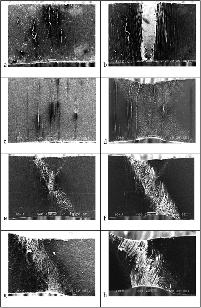
While modification of the strength characteristics of composites is determined by the competition of two processes, namely, strengthening controlled by in situ formation of fibrils and softening related to generation of the shear bands, the effect of fibril formation and shear bands is beneficial to plastic characteristics. In situ tensile testing in the SEM was carried out in order to find the reason for brittle-to-ductile transition of the PLA matrix in PLA/PBAT, PLA/PBASGT blends and composites and to clarify how the morphology of the minor polymer phase affects the mechanism of plastic deformation. It is well understood that fine cracks, well known as crazies, dominate the brittle deformation of amorphous polymer below its Tg.21,22 Dissipation of applied load to these crazies is facilitated by many tiny fibrils connecting their surfaces. Neat amorphous PLA demonstrates a quite brittle fracture with craze nucleation before the yielding and subsequent rapid craze–crack transition.10 Therefore, PLA brittle fracture is observed in the apparent elastic region, below the macroscopic yield stress.Although adding 3 wt% of PBAT or PBASGT is insufficient to alter the deformation mechanism of PLA, the ductility of PLA/PBAT or PLA/PBASGT blends is increased slightly owing to the existence of plenty crazies capable of load-bearing (Table 1). In Fig. 4a and b, as examples, in situ SEM micrographs of the structure evolution of the PLA blend with 3 wt% PBAT are presented. Large number of crazes propagate vertical to the extension in the vicinity of breakage. The density of these crazes decreases gradually moving from fracture zone with highly populated crazes to the sides where no craze is visible, demonstrating districted deformation. Nevertheless, intensive crazing and the related transmission of load provide a delay of transformation of crazes into cracks and material fracture. An analogous situation is observed in the PLA–3 wt% PBASGT blend.
For 6 wt% of PBAT as well as 6 wt% of PBASGT, an increase in the number of crazes which are nucleated and grown is registered (shown in ESI†), and thus further contributes to improved ductility. Substantial changes related to transformation of the plastic deformation mechanism determined by simultaneous crazing and evolution of the shear bands are registered when 10 wt% of PBAT or PBASGT are added into the PLA matrix. As a result, an essential increase in the plasticity of the blend takes place (Tables 1 and 2). It is known that the shear bands are the zones characterized by increased free volume and consequently decreased density of the material, that facilitate the plastic flow. The shear bands are oriented typically at an angle close to ±45° to the deformation direction (the direction of the main tensile stresses). The evolution of the shear bands is the basic mechanism of plastic deformation in ductile materials. In this case, plastic deformation is localized in the system of shear bands. Ductile materials are deformed only within the shear bands. Between the shear bands, the polymer is virtually undeformed. Conversely, the polymer in the region of intersection of the shear bands is highly deformed.
As shown in Fig. 4c and d, an increase in the accumulated strain provides an increment in the concentration of the shear bands. At the same time, the number of crazes remains almost stable. After the neck formation, the shear banding becomes the main mechanism of plastic deformation.
Extrusion of a polymer blend modifies the morphology of the minor polymer phase. Droplets-fiber transition is registered. In the case of in situ generated composites, the formed shear bands are observed together with crazes even at 3 wt% of the PBAT or PBASGT (Fig. 4e and f) that deflect, blunt and terminate crazes and are helpful in initiation of new crazes (Fig. 5a).
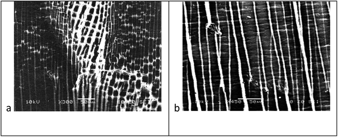 | ||
| Fig. 5 SEM micrographs showing the interaction of crazes and shear bands: PLA/PBASGT (97/3) composite (a) and PLA/PBAT (97/3) composite (b). | ||
For blends, it is worth mentioning the restriction of shear band effects to initiation and termination of crazes. Number of crazes could be proliferated by additional deformation. It should be also noted that in the PLA/3 wt% PBAT composite, formation of so-called dormant shear bands is registered which may stop the propagation of the crazes and stabilize them (Fig. 5b). Moreover, nucleation rate of crazes is intensified due to the sites resulted from dormant shear bands. This effect was reported earlier by us for the PLA/3 wt% PBS composite.10
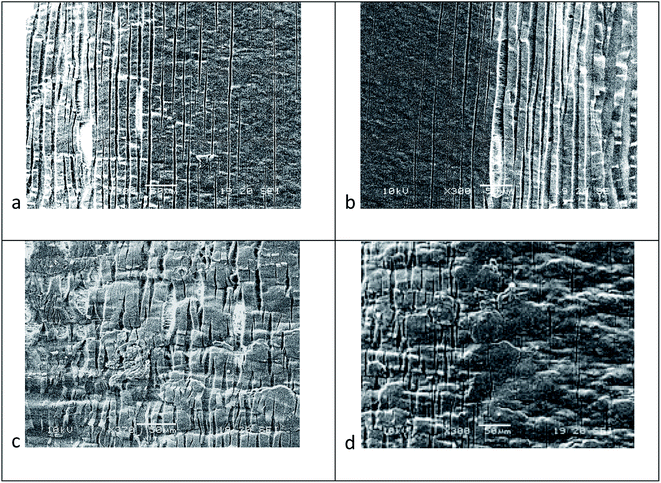
Another specific feature of composites containing 3 wt% of PBAT or PBASGT is severe localization of deformation when a sharp reduction of the density of crazes is registered at the interface of the neck formation zone and non-oriented part of the sample. Besides, the crazes are found thickened. In the non-oriented part of the sample, the crazes are 1–2 μm thin. At the same time, in the zone of the neck formation, they thicken up to few tens of μm (see Fig. 6a and b).
This phenomenon is related to the fact that the craze surfaces are additionally span with nanofibers of PBAT or PBASGT. PLA nanofibrils spanning the surfaces of crazes could stand applied load to some extent, beyond which they get broken. However, the presence of PBAT or PBASGT nanofibrils hinders the fracture through bridging the craze gap. This is in contrast to blends where crazes do not thicken before fracture. An increase in the content of the minor polymer phase in in situ generated composites from 3 wt% to 6 wt% results in gradual change of the main mechanism of plastic deformation from crazing to the shear band formation. In the case of 10 wt% PBAT or PBASGT, plastic deformation of the composite is mostly carried out due to generation and evolution of new shear bands. In Fig. 4g and h, as an example, the structure evolution of PLA/10 wt% PBAT composite subjected to tensile test is shown. The composite structure is almost avoided of crazes. Thus, the main mechanism of plastic deformation of the PLA composites containing 10 wt% of PBAT or PBASGT is shear banding. An analogous situation is associated with the PLA/10 wt% PBASGT composites (shown in ESI†).
So-called dormant shear bands that affect craze evolution have not been found in the structure of composites. As compare to 3 and 6 wt%, adding of 10 wt% of the minor polymer phase (PBAT or PBASGT) provided higher concentration of the shear bands in the neck formation zone, as shown in Fig. 7 for the PLA/10 wt% PBASGT nanocomposite. In the non-oriented parts of the samples of the nanocomposites containing 10 wt% of the minor polymer phase, microcrazes are formed that are generated in the volume of the material (i.e. they do not grow from the upper edge of the sample to the bottom) and characterized by a comparatively small length ranging from 10 to 100 μm.
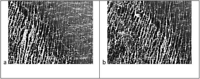 | ||
| Fig. 7 SEM micrographs showing the development of a shear band in PLA/PBASGT (90/10) composite. The respective deformations are 0.250 (a), 0.300 (b). | ||
It is shown in Fig. 6c and d that the concentration of the microcrazes is reduced with the distance from the neck formation zone and the most loaded microcrazes are extended. This fact is an evidence of additional spanning of their surfaces by nanofibers of the minor polymer phase.
3.4 Thermal and dynamic mechanical analysis
It should be noted that the formation of the PLA/PBASGT or PLA/PBAT blends or composites is accompanied by self-nucleation effect.23 The total removal of the melt memory requires heating of a polymer above its equilibrium melting temperature. However the material is molten at relatively low temperature of 180 °C the melt memory is hardly erased at that temperature (Fig. 8). The presence of the centers of self-nucleation also facilitates effective shear-induced crystallization.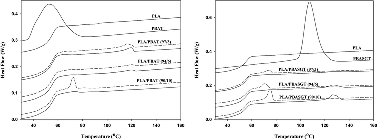 | ||
| Fig. 8 Cooling exotherms of PLA, PBAT, PBASG, PLA/PBAT, PLA/PBASGT. Solid lines – composites, dashed lines – blends. | ||
An important condition of effective conversion of the droplets of the minor polymer into fibers is phase immiscibility of polymer inclusions with polymer matrix.
According to the DSC analysis of PLA/PBAT and PLA/PBASGT (Fig. 9) blends as well as composites, the melting of the minor polymer phase is evidenced by a endothermic peak at about 130 °C (PBAT) or 164 °C (PBASGT).
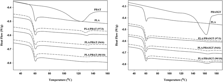 | ||
| Fig. 9 Melting endotherm of PLA, PBAT, PBASG, PLA/PBAT, PLA/PBASGT. Solid lines – composites, dashed lines – blends. | ||
Amorphous PLA is well characterized in Fig. 9 by a glass transition at around 60 °C. This transition is accompanied by a strong enthalpy relaxation originated from chain orientation during the extrusion process. Distinct melting peak of PBASGT or PBAT represents immiscibility of dispersed phase with the matrix, which has no melting peak due to the lack of crystallization. Moreover as compared to neat PBAT, the melting temperature of the PBAT inclusions in the PLA/PBAT blends or composites is 10–12 °C higher (Tables 3 and 4 in ESI†). This fact can be related to the presence of PLA that provides formation of more perfect/thick crystals of PBAT. Similar conclusion about immiscibility of PLA and PBAT or PLA and PBASGT can be drawn based on E′′ data from DMTA measurements (Fig. 4 in ESI†). Nanocomposites can be pelletized and the material can be used for further processing by extrusion, injection molding, thermoforming or other techniques without losing their superior properties provided that the temperature of processing does not exceed the melting temperatures of PBAT or PBASGT nanofibers. It can be concluded that the nanocomposites can be reprocessed without losing their properties, especially preserving yielding and plastic flow (Table 3 in ESI†).
4. Conclusions
The concept of the in situ generation of all-polymer nanocomposites is applied to PLA/PBASGT and PLA/PBAT blends. High shear rate and high elongation strain determine a shift of nonisothermal crystallization temperature by 25 °C (PBASGT) or 20 °C (PBAT) to a higher temperature. The centers of self-nucleation of PBASGT or PBAT that are responsible for the melt memory contribute also to shear-induced crystallization of polymer inclusions. Crystallization of polymer inclusions immediately at the processing temperature without cooling below the nonisothermal crystallization temperature during further processing determines minimization of relaxation processes in the in situ generated polymer fibers and conservation of the achieved degree of elongation of droplet inclusions into fibers. Green biopolymer–biopolymer nanocomposites combining biodegradability, biocompatibility, good strength of PLA and good toughness of PBASGT or PBAT are obtained. The advantages of fibrils/matrix morphology compared to droplets/matrix one, such as increased strength and stiffness of polymer inclusions, the presence of a network of physical entanglements between nanofibrils effectively transmitting mechanical stress, as well as improved interfacial compatibility resulting from a larger specific contact area between phases, contribute to the formation of a better complex of mechanical characteristics (yield stress, modulus, elongation at break and impact strength). Should it be mention that since PLA is amorphous its processing temperature is below the melting of crystalline fibrous PBAT and PBASGT. So the nanocomposites are further processable. An increase in the concentration of the high flexible polymers results in brittle–ductile transition in the PLA matrix. At 3 wt% of polymer inclusions characterized by droplets-like morphology, the crazing is intensified. Adding of 6 wt% of such polymer inclusions is associated with simultaneous development of crazes and shear bands. For 10 wt% of polymer inclusions, shear band formation becomes the main mechanism of plastic deformation. Transition from droplets/matrix to fibrils/matrix morphology determines a more rapid change in the main mechanism of plastic deformation. Even at 3 wt% of in situ generated polymer fibers, intensive crazing is accompanied by evolution of the shear bands. In the case of 6 and 10 wt% of in situ generated polymer fibers, the shear banding becomes the main mechanism of deformation. The formation of PBASGT or PBAT fibers results in additional spanning of the PLA craze surfaces and facilitates an enhancement of strength and plasticity of the PLA matrix.Conflicts of interest
There are no conflicts to declare.Acknowledgements
The project was financed from funds of the National Science Centre (Poland) on the basis of the decisions number DEC-2017/25/B/ST8/02059.References
- F. P. La Mantia and M. Morreale, Green composites: A brief review, Composites, Part A, 2011, 42, 579–588 CrossRef.
- O. Faruk, A. Bledzki, H. P. Fink and M. Sain, Progress report on natural fiber reinforced Composites, Macromol. Mater. Eng., 2014, 299, 9–26 CrossRef CAS.
- M. Kowalczyk, E. Piorkowska, S. Dutkiewicz and P. Sowinski, Toughening of polylactide by blending with a novel random aliphatic–aromatic copolyester, Eur. Polym. J., 2014, 59, 59–68 CrossRef CAS.
- Z. Bartczak, A. Galeski, M. Kowalczuk, M. Sobota and R. Malinowski, Tough blends of poly (lactide) and amorphous poly ([R, S]-3-hydroxy butyrate)–morphology and properties, Eur. Polym. J., 2013, 49, 3630–3641 CrossRef CAS.
- L. Quiles-Carrillo, N. Montanes, D. Garcia-Garcia, A. Carbonell-Verdu, R. Balart and S. Torres-Giner, Effect of different compatibilizers on injection-molded green composite pieces based on polylactide filled with almond shell flour, Composites, Part B, 2018, 147, 76–85 CrossRef CAS.
- J. Balart, V. Fombuena, O. Fenollar, T. Boronat and L. Sánchez-Nacher, Processing and characterization of high environmental efficiency composites based on PLA and hazelnut shell flour (HSF) with biobased plasticizers derived from epoxidized linseed oil (ELO), Composites, Part B, 2016, 86, 168–177 CrossRef CAS.
- L. Wang, J. Qiu, E. Sakai and X. Wei, The relationship between microstructure and mechanical properties of carbon nanotubes/polylactic acid nanocomposites prepared by twin-screw extrusion, Composites, Part A, 2016, 89, 18–25 CrossRef CAS.
- A. R. Kakroodi, Y. Kazemi, W. D. Ding, A. Ameli and C. B. Park, Poly (lactic acid)-based in situ microfibrillar composites with enhanced crystallization kinetics, mechanical properties, rheological behavior, and foaming ability, Biomacromolecules, 2015, 16, 3925–3935 CrossRef CAS.
- L. Xie, H. Xu, B. Niu, X. Ji, J. Chen, Z. M. Li, B. S. Hsiao and G. J. Zhong, Unprecedented access to strong and ductile poly (lactic acid) by introducing in situ nanofibrillar poly (butylene succinate) for green packaging, Biomacromolecules, 2014, 15, 4054–4064 CrossRef CAS.
- Yu. Voznyak, J. Morawiec and A. Galeski, Ductility of polylactide composites reinforced with poly (butylene succinate) nanofibers, Composites, Part A, 2016, 90, 218–224 CrossRef CAS.
- A. D. Kakroodi, Y. Kazemi, M. Nofar, B. Chul and C. B. Park, Tailoring poly (lactic acid) for packaging applications via the production of fully bio-based in situ microfibrillar composite films, Chem. Eng. J., 2017, 308, 772–782 CrossRef CAS.
- S. Fakirov, in Synth Polym Compos, ed. S. Bhattacharyya and S. Fakirov, Hanser Publications, Munich, 2012, p. 353 Search PubMed.
- W. Ding, Y. Chen, Z. Liu and S. Yang, In situ nano-fibrillation of microinjection molded poly (lactic acid)/poly (ε-caprolactone) blends and comparison with conventional injection molding, RSC Adv., 2015, 5, 92905–92917 RSC.
- P. Cassagnau and A. Michel, New morphologies in immiscible polymer blends generated by a dynamic quenching process, Polymer, 2001, 42, 3139–3152 CrossRef CAS.
- J. X. Li, J. Wu and C. M. Chan, Thermoplastic nanocomposites, Polymer, 2000, 41, 6935–6937 CrossRef CAS.
- M. Wojtczak, S. Dutkiewicz, A. Galeski and A. Gutowska, Classification of aliphatic-butylene terephthalate copolyesters in relation to aliphatic/aromatic ratio, Polymer, 2017, 113, 119–134 CrossRef CAS.
- A. Baji, S. C. Wong, T. Liu, T. Li and T. S. Srivatsan, Morphological and X-ray diffraction studies of crystalline hydroxyapatite-reinforced polycaprolactone, J. Biomed. Mater. Res., Part B, 2007, 81, 343–350 CrossRef.
- Y. He, T. Wu, J. Wie, Z. Fan and S. Li, Morphological investigation on melt crystallized polylactide homo-and stereocopolymers by enzymatic degradation with proteinase K, J. Polym. Sci., Part B: Polym. Phys., 2008, 46, 959–970 CrossRef CAS.
- J. Bojda and E. Piorkowska, Shear-induced nonisothermal crystallization of two grades of PLA, Polym. Test., 2016, 50, 172–181 CrossRef CAS.
- M. Wojtczak, S. Dutkiewicz, A. Galeski and E. Piorkowska, Structure and characterization of random aliphatic–aromatic copolyester, Eur. Polym. J., 2014, 55, 86–97 CrossRef CAS.
- A. M. Donald, E. J. Kramer and R. P. Kambour, Interaction of crazes with pre-existing shear bands in glassy polymers, J. Mater. Sci., 1982, 17, 1739–1744 CrossRef CAS.
- M. E. J. Dekkers and D. Heikens, Crazing and shear deformation in glass bead-filled glassy polymers, J. Mater. Sci., 1985, 20, 3873–3880 CrossRef CAS.
- M. Wojtczak, S. Dutkiewicz, L. Pietrzak, A. Galeski and E. Piorkowska, Nucleation and crystallization of random aliphatic-butylene terephtalate copolyester, Eur. Polym. J., 2015, 71, 289–303 CrossRef CAS.
Footnote |
| † Electronic supplementary information (ESI) available. See DOI: 10.1039/c9ra05919a |
| This journal is © The Royal Society of Chemistry 2019 |

