
 Open Access Article
 This Open Access Article is licensed under a
 Creative Commons Attribution 3.0 Unported Licence
Giant enhancement of tunable asymmetric transmission for circularly polarized waves in a double-layer graphene chiral metasurface
Jiaxin Zhouab,
Yueke Wang *ab,
Mengjia Luab,
Jian Dingab and
Lei Zhouab
*ab,
Mengjia Luab,
Jian Dingab and
Lei Zhouab
aOptical Information Science and Technology Department, Jiangnan University, Wuxi, Jiangsu 214122, China. E-mail: ykwang@jiangnan.edu.cn
bOptoelectronic Engineering and Technology Research Center, Jiangnan University, Wuxi, Jiangsu 214122, China
First published on 21st October 2019
Abstract
In this letter, we propose a structure based on double-layer graphene-based planar chiral metasurface with a J-shaped pattern to generate asymmetric transmission for circularly polarized waves in the mid-infrared region. Asymmetric transmission of the double-layer structure can reach to 16.64%, which is much larger than that of the monolayer. The mechanism of asymmetric transmission is attributed to enantiomerically sensitive graphene's surface plasmons. Besides, asymmetric transmission can be dynamically tuned by changing the Fermi energy and is affected by intrinsic relaxation time. All simulations are conducted by the finite element method. Our findings provide a feasibility of realizing photonic devices in tunable polarization-dependent operation, such as asymmetric wave splitters and circulators.
Introduction
In recent years, chiral metasurfaces have become more and more popular in many fields such as optics. Chirality means that an object cannot be coincident with its mirror image. Existing studies of chiral metamaterials mainly focus on circular1–4 and elliptical dichroism,5 asymmetric transmission for linearly polarized waves in three-dimensionally chiral planar structures6–9 and for circularly polarized waves in two-dimensionally planar chiral structures.10,11 Compared with conventional gyrotropy and optical Faraday effects, asymmetric transmission has completely different properties in planar chiral structures. Asymmetric transmission of chiral metasurfaces for circularly polarized waves can be defined as the total transmission difference between the same handedness waves propagating in the opposite directions or the opposite handedness waves propagating in the same direction.12 With the development of research on chirality with asymmetric transmission, electromagnetic devices applied for both linearly and circularly polarized waves have been designed, such as some polarization transformers, polarization analysers and polarization-controlled devices.13–16 They are widely used to promote the evolution of optical communication and photonics. The excitation of enantiomerically sensitive surface plasmons is a collective mode of electron oscillation at the interface of conductor and medium, which is in charge of asymmetric transmission for circularly polarized waves in planar chiral metasurfaces.17–19As a kind of promising electrically tunable plasmonic material, periodical graphene metasurfaces can excite graphene surface plasmons in the mid-infrared and terahertz (THZ) region.20–22 And for graphene metasurface, novel optical properties are dynamically tunable by changing the Fermi energy through voltage control or the changing intrinsic relaxation time through chemical doping.23–26 Compared with metallic surface plasmons, graphene surface plasmons have the advantages of low loss, and high localization.27 Thus, graphene will revolutionize metamaterials and metadevices, and promote the development of nano-optics.28 There are plenty of researches on metallic chiral metamaterials,29 but they are generally not tunable, which can be easily realized in graphene metasurface. Recently, people propose kinds of monolayer graphene chiral metasurface,30,31 and study the asymmetric transmission for circularly polarized waves. The researches of graphene planar chiral structure will deepen the understanding of the interaction between light and matter in planar chiral structure, which can be applied to tunable polarization sensitive devices, and circular polarizers. But the asymmetric transmission of monolayer graphene chiral metasurface is only up to 5%.
In this letter, we propose a double-layer graphene-based planar chiral metasurface structure to achieve giant enhancement of asymmetric transmission for circularly polarized waves incidence in mid-infrared region. In the monolayer metasurface which is composed of J-shaped hollow graphene patterns, the asymmetric transmission ΔT can reach a small value of 2.05%. When another J-shaped pattern, which is designed to be rotated by 90 degrees after being mirror symmetric operation with respect to the previous layer, is added, the asymmetric transmission ΔT can achieve 16.64%. The mechanism of asymmetric transmission can be explained with the enantiomerically sensitive graphene surface plasmons, which induce the charge-field excitations. Also, the peaks of asymmetric transmission blue shift with increasing Fermi level, and the values of peaks increase with increasing electron scattering time. Finite Element Method (FEM) simulations are conducted to verify our findings.
Methods and results
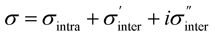
Firstly, we discuss the monolayer graphene metasurface, and one unit is shown in Fig. 1(a). Here, the graphene sheet is transferred to the quartz substrate, and is decorated with hollow periodic J-shaped patterns. Our proposed structure is two-dimensionally chiral due to non-mirror symmetry, which may lead to asymmetric transmission for circularly polarized waves. Here, the permittivity of the quartz substrate is 2.25. The period p of the structure is set to be 270 nm, and the other parameters of the pattern are displayed in the Fig. 1(b). The widths of the top side and the bottom side of J-shaped patterns are ax = 230 nm and m = 125 nm, respectively. The length of J-shaped pattern is ay = 210 nm, and the width of hollow area is w = 20 nm. Periodic boundary conditions are set along x and y directions for our periodical structure and perfectly matching layers are set in z direction to achieve the minimal reflection for the outgoing electromagnetic wave.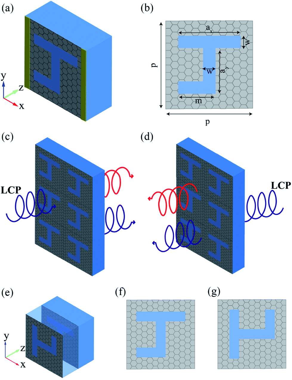 | ||
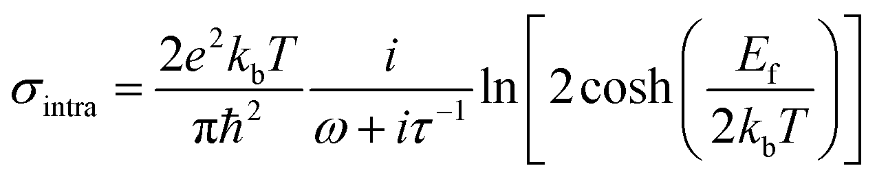
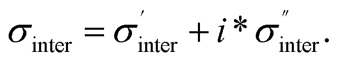
| Fig. 1 (a) The schematic diagram of one unit of the monolayer graphene-based planar chiral metasurface. (b) The geometric parameters of the hollow J-shaped pattern. LCP incident from the (c) front side and (d) back side of the monolayer graphene-based planar chiral metasurface. (e) One cell of double-layer J-shaped graphene-based planar chiral metasurface. The pattern of (f) the bottom layer and (g) the upper layer. | ||
According to the Kubo formula, the conductivity of graphene consists of two parts: intraband and interband elements:32
 | (1) |
 | (2) |
 Here,
Here, 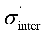 can be expressed as:
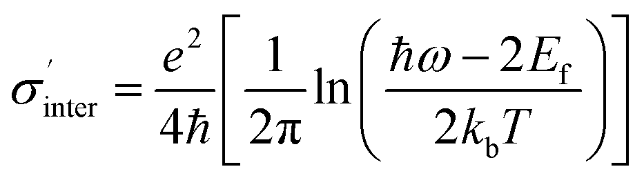 | (3) |
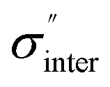 can be expressed as:
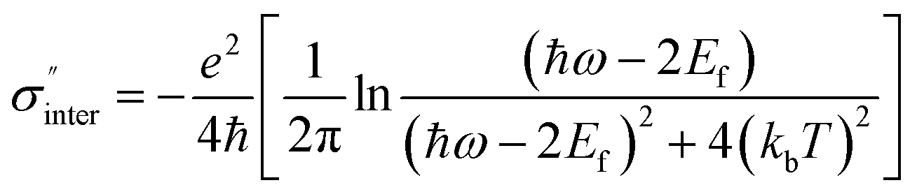 | (4) |
![[thin space (1/6-em)]](https://www.rsc.org/images/entities/char_2009.gif) 000 cm2 V–1 S−1, respectively,22,33 thus τ is 0.8 ps.
000 cm2 V–1 S−1, respectively,22,33 thus τ is 0.8 ps.
The pattern of the J-shaped graphene metasurface has a character of chirality, which can reveal asymmetric transmission when the incident circularly polarized waves have different handedness or propagation directions. Fig. 1(c) and (d) demonstrate the different incident directions of LCP waves, which are coming perpendicularly from the front and the back of monolayer graphene-based planar chiral metasurface. In the complex circular transmission matrices Ei = tijE0j, the indices i, j represents right-handed circularly polarized (RCP) or left-handed circularly polarized (LCP) components. The transmission matrix elements are defined as Tij = |tij|2. The circular transmission T can be applied to any dispersive optical system under the condition of coherent light incidence. The transmission matrix elements are the same for circularly polarized waves of opposite handedness propagating in opposite directions. It means that the LCP(RCP) waves incident forward equal to the RCP(LCP) waves incident backward. Thus, we can define the transmittances of the LCP waves with opposite propagation directions as
| Tf = |tLL|2 + |tRL|2 | (5) |
| Tb = |tRR|2 + |tLR|2 | (6) |
| ΔT = ΔLCPcirc = Tf − Tb = −ΔRCPcirc | (7) |
Thus, the asymmetric transmission is only decided by circular polarization conversion transmission.
Fig. 2(a) and (b) show the calculated results of the four transmission matrix elements when the Fermi energy Ef is fixed to be 0.80 eV, for the monolayer J-shaped graphene metasurface. Black and red lines represent LCP incidence along the forward and backward directions, respectively. It is found that the direct transmissions (TLL and TRR) always keeps the same with each other with the wavelength changing, and reaches minimum when the incident wavelength is 14.83 μm, shown as Fig. 2(a). It proves that graphene-based planar chiral metasurface is lack of circular dichroism. In Fig. 2(b), TRL is always a little larger than TLR with the wavelength ranging from 13 to 17 μm, and the maxima of TRL and TLR are 15.07% and 13.02% at 14.83 μm, respectively. Thus, the asymmetric transmission for LCP waves reaches the maximum value of 2.05% at the wavelength of 14.83 μm, as shown in Fig. 2(c). It is believed that the graphene surface plasmon is resonantly excited along the edges of the hollow J-shaped pattern at 14.83 μm, and in charge of the asymmetric transmission. For RCP incident waves, the asymmetric transmission is quite the contrary to that of LCP incidence based on eqn (7), shown as Fig. 2(d).
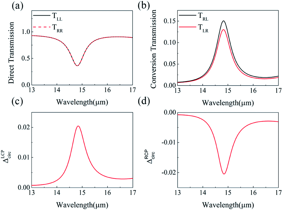 | ||
| Fig. 2 (a) Direct transmission TLL and TRR and (b) circular polarization conversion transmission TRL and TLR with wavelength for the monolayer J-shaped graphene metasurface. Asymmetric transmission for (c) LCP waves and (d) RCP waves. The Fermi energy is fixed at 0.80 eV. | ||
Although the asymmetric transmission has been obtained, the ΔT is small, compared with that of metallic planar chiral metamaterial structure.34,35 To realize larger asymmetric transmission, a double-layer structure is proposed based on the monolayer graphene-based J-shaped metasurface structure. Fig. 1(e) shows the structure composed of two graphene-based planar metasurface layers with J-shaped patterns. The pattern of the bottom layer is shown as Fig. 1(f), which is the same with the monolayer structure of Fig. 1(b); while the upper layer shown as Fig. 1(g) is the pattern of the bottom J-shaped pattern being clockwise rotated by 90 degrees after mirror symmetric transformation about y-axis. The medium between the two graphene layers is quartz, and the thickness of the quartz is 125 nm. The LCP waves are still coming perpendicularly from the front and the back of graphene-based planar chiral metasurfaces, respectively.
Fig. 3(a) and (b) show the calculated results of the four transmission matrix elements, when the Fermi energy Ef is fixed to be 0.80 eV for the double-layer structure shown as Fig. 1(e). Fig. 3(a) shows that TLL and TRR are still identical, which proves that asymmetric transmission is independent of direct transmission. In Fig. 3(b), the transmission matrix element TRL is slightly higher than that of the monolayer chiral metasurface shown in Fig. 2(b), while TLR goes down sharply to almost zero at the wavelength of 14.90 μm. Compared with the monolayer J-shaped metasurface, the resonant wavelength of graphene surface plasmon redshifts a little. Due to the existence of the near to zero value of TLR, the asymmetric transmission ΔT can be increased a lot. As shown in the Fig. 3(c), the maximum of ΔT can reach 16.64% at the wavelength of 14.90 μm, which is much larger than 2.05% of the monolayer graphene-based planar chiral metasurface. Similarly, the asymmetric transmission peak of RCP incident waves reaches −16.64%, just the opposite of LCP. The giant enhancement of circular asymmetric transmission suggests that the structure of double-layer J-shaped graphene metasurface can greatly improve chirality.
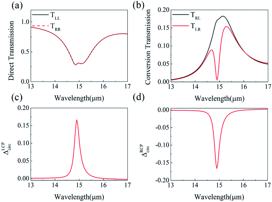 | ||
| Fig. 3 (a) Direct transmission, (b) conversion transmission matrix elements, and the asymmetric transmission for (c) LCP waves and (d) RCP waves of double-layer graphene-based planar chiral metasurface with wavelength changing. The Fermi energy is fixed at 0.80 eV. | ||
In order to understand the physical mechanisms behind the asymmetric transmission, the induced electric field in the hollow area of the bottom layer of graphene metasurface is studied in Fig. 4 and the induced electric vector field is indicated by red arrows. At the resonance wavelength, a standing wave of current oscillations is excited by electromagnetic radiation. This coupled oscillation of the electron density and electromagnetic field is a localized plasmon. Plasmonic excitation of chiral structure is different from that of ordinary metamaterials since it is enantiomerically sensitive.36 The excitation level is decided by the direction and polarization state of the incident waves. Here, graphene localized surface plasmon is excited along the J-shaped edge because the electric field is enhanced around the J-shaped edge shown in Fig. 4. Here, the asymmetric transmission is attributed to the enantiomerically sensitive graphene surface plasmons. When the LCP (or RCP) at the resonance wavelength is incident on the graphene metasurface from the forward (or the backward) direction, the enantiomerically graphene surface plasmon is excited, enhances the local electric field, and excites the induced electric field in the substrate, which determines the radiation (direct transmission, and conversion transmission). The striking difference between plasmonic excitations of opposite handedness leads to the different induced electric field. With greater chirality, the induced electric field is more different and the difference of the circular polarization conversion between the opposite handedness will be stronger. The components Ey of the induced electric field for LCP(RCP) incidences can reflect the excitation level of localized plasmon, and explain the difference between TLR and TRL. Here, the yellow and green arrows was painted to demonstrate the components Ey along y-directions as shown in Fig. 4. Fig. 4(a) and (b) show the induced electric field distribution under the monolayer graphene metasurface in the substrate. The green arrows for the RCP incidence are stronger than that of the LCP incidence for the monolayer metasurface structure, which indicates the suppression of circular polarization conversion is stronger. Thus, TLR is smaller than TRL, and an asymmetric transmission (ΔT = TRL − TLR) of 2.05% is achieved for the monolayer metasurface structure. Fig. 4(c) and (d) show the induced electric field distribution under the double-layer graphene metasurface in the substrate when the incident wavelength is 14.90 μm. The induced electric field components Ey for the LCP incidence indicated by yellow arrows in Fig. 4(c) are stronger than those in Fig. 4(a), which indicates that the suppression of circular polarization conversion is smaller. Thus, TRL of double-layer increases to 17.13%, compared with 15.07% of the monolayer. As shown in the Fig. 4(d), more electric fields indicated by the green arrows and less electric fields indicated by the yellow arrows than those of Fig. 4(b) means that the electric field is weakly coupling to free space, scattering is low and suppression of circular polarization conversion is much stronger than that of monolayer metasurface.17,36 Thus, TLR is near to zero, and the asymmetric transmission of the double-layer metasurface can be greatly increased and ΔT can reach 16.64%.
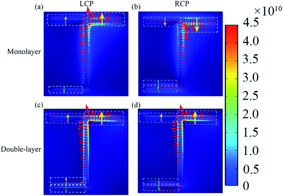 | ||
| Fig. 4 The induced electric field in the hollow area of the bottom layer of graphene chiral planar metasurface at the resonance wavelengths (a) LCP and (b) RCP waves propagating along the forward direction for the monolayer structure when the wavelength is 14.83 μm; (c) LCP and (d) RCP waves propagating along the forward direction for the double-layer structure when the wavelength is 14.90 μm. | ||
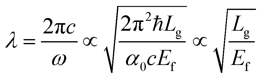
To study the dynamical tunability of asymmetric transmission, we changed the Fermi energy and intrinsic relaxation time of graphene layers. When increasing the Fermi energy from 0.76 to 1.00 eV, the peak of asymmetric transmission has a blue shift changing from 15.30 to 13.30 μm, as shown in Fig. 5(a). It suggests that graphene-based planar chiral metasurface layer structure has a feasibility of realizing polarization sensitive devices in a wide wavelength range. This blue shift behaviour can be interpreted by the following: the excitation of graphene surface plasmonic wave vector is satisfied with the equation Kspp = ħω2/2α0Efc ∝ 1/Lg37 where α0 = e2/ħc is the fine structure constant. The resonant wavelength λ can be written as:
 | (8) |
000 cm2 V–1 S−1, so intrinsic relaxation time τ can vary from 0.24 to 0.80 ps. With the increase of intrinsic relaxation time τ, the peak value of the asymmetric transmission increases from 5.95% to 16.64%, and the peak position remains unchanged, always at the wavelength of 14.90 μm. This increase of the asymmetric transmission peak value with increasing electron scattering time τ is caused by the reduced free-carrier loss in graphene, which can lead to a increase in the circular polarization conversion transmission TRL but no change of TLR. Therefore, the frequency peak position of asymmetric transmission can be tuned because the Fermi energy can be changed by tuning the gate voltage, compared with the metallic chiral metamaterials. For tuning the Fermi energy of graphene in the potential experiments, we can cover the structure with a layer of ion gel following the procedure described in ref. 38. A top gate gold contact is fabricated on the ion gel layer and the bottom gate is connected to silica bottom. The fermi energy of the graphene nanostructure could be tuned by applying a bias voltage.39
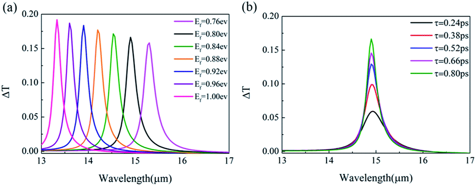 | ||
| Fig. 5 (a) The relation between the asymmetric transmission ΔT and wavelength under different Fermi energy. (b) The relation between ΔT and wavelength under different scattering time τ, when Ef is 0.8 eV. Other parameters are the same with that of Fig. 1(e). | ||
Other double-layer structures of J-shaped pattern have been also studied, and circular polarization conversion are calculated, when Ef is fixed to be 0.80 eV. Fig. 6(a), (d) and (g) show the upper patterns of the three typical kinds of double-layer structures, which are the same with the bottom layer pattern, the bottom layer pattern being rotated by 90 degrees and the bottom layer pattern being mirror rotated about y-axis, respectively. Fig. 6(b), (e) and (h) show the circular polarization conversion of the three kinds of two-layer structures, it is found that the difference between TLR and TRL varies with wavelength. For the structures of Fig. 6(a) and (g), the asymmetric transmission can reach maximum 5.19% and 7%, when λ locates at 15.1 and 14.8 μm, shown as Fig. 6(c) and (i). And for the structure of 90 degrees rotation, the asymmetric transmission almost disappears. Thus, the largest asymmetric transmission can be obtained for the double-layer structure of Fig. 1(e).
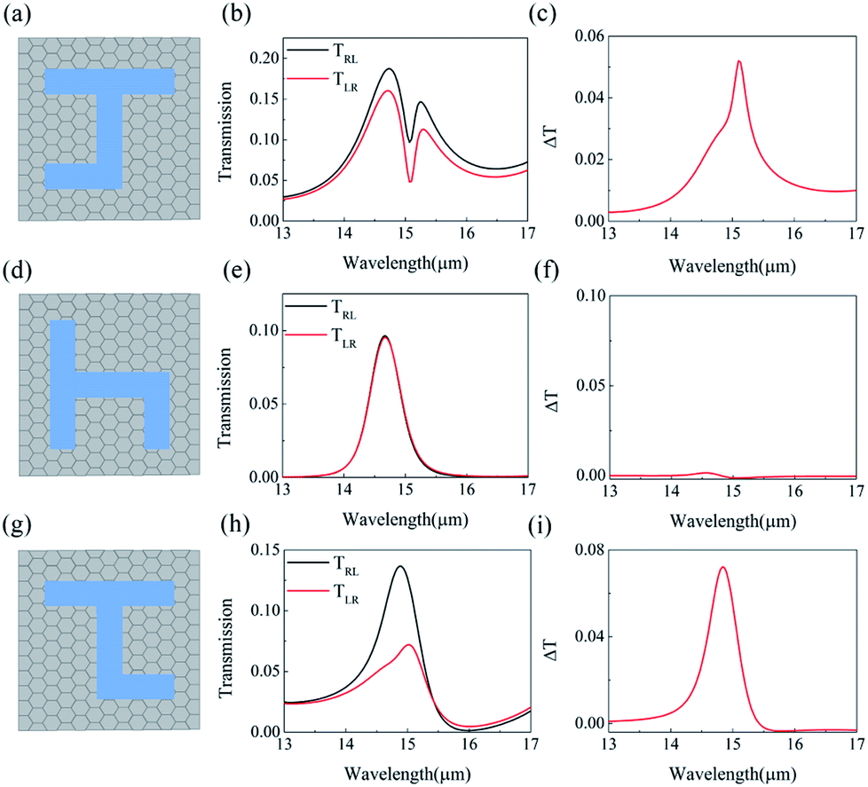 | ||
| Fig. 6 The upper patterns of the three typical kinds of double-layer structures, which are the same with the bottom layer pattern (a), the bottom layer pattern being rotated by 90 degree (d) and the bottom layer pattern being mirror rotated about y-axis (g), respectively. The conversion transmissions (b), (e) and (h) and the asymmetric transmissions (c), (f) and (i) for structures of (a), (d), and (g), respectively. | ||
Conclusions
In summary, we demonstrated and studied the double-layer graphene-based planar chiral metasurfaces structure. Through FEM numerical simulation, we chose the most suitable orientation of double-layer graphene pattern, and the asymmetric transmission can reach to 16.64%, which is much larger than that of the monolayer. In addition, the induced electric field below the graphene chiral metasurfaces are analyzed for understanding the physical mechanism of asymmetric transmission. We attribute the asymmetric transmission for circularly polarized waves to the enantiomerically sensitive plasmonic excitations. Besides, the peak of asymmetric transmission could have frequency shift and amplitude changes when the Fermi energy and intrinsic relaxation times of graphene are changed. We believe our findings can be applied to tunable polarization sensitive devices, circular polarizers and other fields.Conflicts of interest
There are no conflicts to declare.Acknowledgements
This project was supported by National Natural Science Foundation of China under Grant No. 1148081606193050, Ministry of Education of the People's Republic of China under 1148081606193200, the Fundamental Research Funds for the Central Universities under Grant No. JUSRP115A15, JUSRP21935 and JUSRP51628B, and the Undergraduate Innovation Training Program of Jiangnan University of China under no. 1145210232186110.Notes and references
- A. B. Khanikaev, N. Arju, Z. Fan, D. Purtseladze, F. Lu, J. Lee, P. Sarriugarte, M. Schnell, R. Hillenbrand, M. A. Belkin and G. Shvets, Nat. Commun., 2016, 7, 12045 CrossRef CAS
.
- D. Vestler, I. Shishkin, E. A. Gurvitz, M. E. Nasir, A. Ben-Moshe, A. P. Slobozhanyuk, A. V. Krasavin, T. Levi-Belenkova, A. S. Shalin, P. Ginzburg, G. Markovich and A. V. Zayats, Opt. Express, 2018, 26, 17841–17848 CrossRef CAS
- X. T. Kong, L. Khosravi Khorashad, Z. Wang and A. O. Govorov, Nano Lett., 2018, 18, 2001–2008 CrossRef CAS PubMed
- B. Liu and Y. Jiang, Appl. Phys. Lett., 2018, 112, 173503 CrossRef
- J. Hofbrucker, A. V. Volotka and S. Fritzsche, Phys. Rev. Lett., 2018, 121, 053401 CrossRef CAS
- X. Shang, X. Zhai, L. Wang, M. He, Q. Li, X. Luo and H. Duan, Appl. Phys. Express, 2017, 10, 052602 CrossRef
- C. Menzel, C. Helgert, C. Rockstuhl, E.-B. Kley, A. Tunnermann, T. Pertsch and F. Lederer, Phys. Rev. Lett., 2010, 104, 253902 CrossRef CAS
- J. Shi, X. Liu, S. Yu, T. Lv, Z. Zhu, H. Ma and T. Cui, Appl. Phys. Lett., 2013, 102, 191905 CrossRef
- T. Lv, Y. Li, H. Ma, Z. Zhu, Z. Li, C. Guan, J. Shi, H. Zhang and T. Cui, Sci. Rep., 2016, 6, 23186 CrossRef CAS
- W. Ji, T. Cai, G. Wang, H. Li, C. Wang, H. Hou and C. Zhang, Opt. Express, 2019, 27, 2844–2854 CrossRef CAS
- O. Arteaga, J. Sancho-Parramon, S. Nichols, B. M. Maoz, A. Canillas, S. Bosch, G. Markovich and B. Kahr, Opt. Express, 2016, 24, 2242–2252 CrossRef CAS
- V. A. Fedotov, P. L. Mladyonov, S. L. Prosvirnin, A. V. Rogacheva, Y. Chen and N. I. Zheludev, Phys. Rev. Lett., 2006, 97, 167401 CrossRef CAS
- W. Shen, C. Hu, S. Huo, Z. Sun, S. Fan, J. Liu and X. Hu, Opt. Lett., 2018, 43, 1255–1258 CrossRef CAS
- Y. Cheng, R. Gong and L. Wu, Plasmonics, 2017, 12, 1113–1120 CrossRef CAS
- C. Guo, F. Liu, S. Chen, C. Feng and Z. Zeng, Commun. Surv. Tutorials, IEEE, 2017, 19, 125–166 Search PubMed
- T. Low and P. Avouris, ACS Nano, 2014, 8, 1086–1101 CrossRef CAS
- E. Plum, V. A. Fedotov and N. I. Zheludev, Appl. Phys. Lett., 2009, 94, 131901 CrossRef
- R. Singh, E. Plum, C. Menzel, C. Rockstuhl, A. K. Azad, R. A. Cheville, F. Lederer, W. Zhang and N. I. Zheludev, Phys. Rev. B: Condens. Matter Mater. Phys., 2009, 80, 153104 CrossRef
- N. Parappurath, F. Alpeggiani, L. Kuipers and E. Verhagen, ACS Photonics, 2017, 4, 884–890 CrossRef CAS
- D. Jin, T. Christensen, M. Soljačić, N. X. Fang, L. Lu and X. Zhang, Phys. Rev. Lett., 2017, 118, 245301 CrossRef
- Q. Guo, R. Yu, C. Li, S. Yuan, B. Deng, F. Javier García de Abajo and F. Xia, Nat. Mater., 2018, 17, 986–992 CrossRef CAS
- M. Jablan, H. Buljan and M. Soljačić, Phys. Rev. B: Condens. Matter Mater. Phys., 2009, 80, 245435 CrossRef
- V. Semenenko, S. Schuler, A. Centeno, A. Zurutuza, T. Mueller and V. Perebeinos, ACS Photonics, 2018, 5, 3459–3465 CrossRef CAS
- X. He, Carbon, 2015, 82, 229–237 CrossRef CAS
- J. I.-J. Wang, D. Rodan-Legrain, L. Bretheau, D. L. Campbell, B. Kannan, D. Kim, M. Kjaergaard, P. Krantz, G. O. Samach, F. Yan, J. L. Yoder, K. Watanabe, T. Taniguchi, T. P. Orlando, S. Gustavsson, P. Jarillo-Herrero and W. D. Oliver, Nat. Nanotechnol., 2019, 14, 120–125 CrossRef CAS
- H. Liu, Y. Liu and D. Zhu, J. Mater. Chem. A, 2011, 21, 3335–3345 RSC
- C. Wang and D. Astruc, Prog. Mater. Sci., 2018, 94, 306–383 CrossRef CAS
- Y. Chen, J. Zhu, Y. Xie, N. Feng and Q. H. Liu, Nanoscale, 2019, 11, 9749–9755 RSC
- L. Wu, Z. Yang, Y. Cheng, M. Zhao, R. Gong, Y. Zheng, J. Duan and X. Yuan, Appl. Phys. Lett., 2013, 103, 021903 CrossRef
- Z. Li, W. Liu, H. Cheng, S. Chen and J. Tian, Opt. Lett., 2016, 41, 3142–3145 CrossRef CAS
- Y. Huang, Z. Yao, F. Hu, C. Liu, L. Yu, Y. Jin and X. Xu, Carbon, 2017, 119, 305–313 CrossRef CAS
- K. S. Novoselov, A. K. Geim, S. V. Morozov, D. Jiang, Y. Zhang, S. V. Dubonos, I. V. Grigorieva and A. A. Firsov, Science, 2004, 306, 666–669 CrossRef CAS
- N. Papasimakis, S. Thongrattanasiri, N. I. Zheludev and F. J. García de Abajo, Light: Sci. Appl., 2013, 2, e78 CrossRef
- C. Pan, M. Ren, Q. Li, S. Fan and J. Xu, Appl. Phys. Lett., 2014, 104, 121112 CrossRef
- B. Lin, J. Guo, P. Chu, W. Huo, Z. Xing, B. Huang and L. Wu, Phys. Rev. Appl., 2018, 9, 024038 CrossRef CAS
- V. A. Fedotov, A. S. Schwanecke and N. I. Zheludev, Nano Lett., 2007, 7, 1996–1999 CrossRef CAS
- F. H. L. Koppens, D. E. Chang and F. Javier García de Abajo, Nano Lett., 2011, 11, 3370–3377 CrossRef CAS
- C. F. Chen, C. H. Park, B. W. Boudouris, J. Horng, B. Geng, C. Girit, A. Zettl, M. F. Crommie, R. A. Segalman, S. G. Louie and F. Wang, Nature, 2011, 471, 617–620 CrossRef CAS PubMed
- Z. Fang, S. Thongrattanasiri, A. Schlather, Z. Liu, L. Ma, Y. Wang, P. M. Ajayan, P. Nordlander, N. J. Halas and F. J. García de Abajo, ACS Nano, 2013, 7, 2388–2395 CrossRef CAS
| This journal is © The Royal Society of Chemistry 2019 |