 Open Access Article
Synthesis and characterization of a novel ruthenium(II) trisbipyridine complex magnetic nanocomposite for the selective oxidation of phenols
Zhengxin Feiab,
Feng Chena,
Mingqiang Zhonga,
Jianping Qiub,
Weidong Li *c and
Seyed Mohsen Sadeghzadeh
 de
de
aCollege of Material Science and Engineering, Zhejiang University of Technology, Hangzhou 310014, China
bJinhua Polytechnic, Jinhua 321007, China
cPolytechnic Institute of Qianjiang College, Hangzhou Normal University, Hangzhou, 310018, China. E-mail: lwd@hznu.edu.cn
dNew Materials Technology and Processing Research Center, Department of Chemistry, Neyshabur Branch, Islamic Azad University, Neyshabur, Iran
eYoung Researchers and Elite Club, Neyshabur Branch, Islamic Azad University, Neyshabur, Iran
First published on 6th September 2019
Abstract
Anchoring ruthenium(II) trisbipyridine complex [Ru(Bpy)3]2+ into a magnetic dendritic fibrous silica nanostructure produces an unprecedented strong nanocatalyst, FeNi3/DFNS/[Ru(Bpy)3]2+. Impressive oxidation of phenols to 1,4-benzoquinones catalyzed by FeNi3/DFNS/[Ru(Bpy)3]2+ is obtained in acetonitrile and water solution with molecular dioxygen as oxidant. Exclusively, apparently inert phenols such as phenol itself and mono-alkyl-substituted phenols are impressively oxidized to produce 1,4-benzoquinones through activation of the C–H bond in the position para to the carbon–oxygen bond under mild conditions. In addition, the production of industrially significant quinones that are known intermediates for vitamin combinations is investigated and studied FeNi3/DFNS/[Ru(Bpy)3]2+ magnetic nanoparticles were produced, and their properties were investigated by AFM, FTIR, XRD, TGA, SEM, TEM, and VSM.
Introduction
Recently, the use of surfactant on soft template has led to the production of mesoporous silica with dendritic silica fiber morphology (DFNS). Silicas possessing this morphology are being tested experimentally as support materials for catalysis and adsorption processes. The outward radial widening of these silicas provides higher surface area for reactants to access the functional materials more efficiently. In addition to that, DFNS has intrinsic mesoporous properties, is thermally stable and exhibits high activity. The synthesis of DFNS requires a microemulsion system that contains surfactant, oil and water. Furthermore, the particle size and morphology of DFNS can be easily manipulated by introducing co-surfactant and various cosolvents.1–7The alloy FeNi3 is magnetic and is utilized for its high permeability, low energy losses, high temperature and high saturation magnetism. Nevertheless, this nano adsorbent is subject to rusting and so researchers commonly utilize functionalized metal oxides and polymers as well as antioxidants. The coating of SiO2 with FeNi3 nanoparticles may impressively enhance the electrical contact of materials in high-frequency applications. Currently, distinct approaches are utilized for providing nanocomposites of magnetic alloys and their nanoparticles. Nevertheless, in most cases, they need excessive as well as inappropriate conditions such as vacuum, inert atmosphere and sometimes hydrogen, high pressure and temperature. Moreover, studying the risks associated with Fe nanoparticles is a priority.8–14
Recently, half-sandwich complexes of organoruthenium have been much studied because of their catalytic and pharmacological characteristics.15,16 Their reactivity, biological activity17,18 and also their catalytic activity may possibly be modified using appropriate ligand selection.19–21 Loading them onto macromolecular systems such as dendrimers, metallocages, liposomes, and nanoparticles equipped Ru(arene) and other metal complexes with the capacity to target tumors.22 By using catalysts on macromolecular supports, problems such as separation of catalyst from the obtained products, and recycling of the catalyst may be solved,23 as was observed in the study by Süss-Fink et al., which was performed for Ru/superparamagnetic iron oxide nanoparticles (SPIONs),24 as well as that by Fan and colleagues relating to Ru(arene) organometallics.25 Moreover, such enhancement opens up opportunities in this field such as molecular nanomagnet development and also single molecule magnet preparation.26,27
The selective oxidation of phenols is of major significance for the production of 1,4-benzoquinones, main intermediates for the production of vitamins E and K. Different oxidant/catalyst combinations like O2 or H2O2/CuCl2, particularly with different co-catalysts, are chosen in this oxidation approach. Nevertheless, the basic difficulty of this approach is that the use of homogeneous catalysts causes issues concerning separation and recycling of the catalyst as well as purification of products. Therefore, the development of more impressive as well as ‘‘green’’ catalysts for the selective oxidation is currently a big challenge.28–32
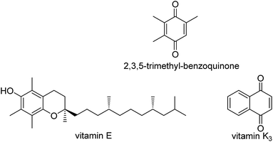
In previous studies, some teams showed that the C–H bond reactivity of phenols in the para-position varied according to the substituents on the benzene ring.33,34 Commonly, when the number of alkyl groups is higher than 3, the C–H bond of these phenols has amplified reactivity.34 The method for oxidation of phenols to 1,4-benzoquinones is relatively straightforward. Multi-alkyl-1,4-benzoquinones are particularly reactive and side-reactions can be occur under oxidation conditions, but the C–H bond in the para-position of phenol and in mono-alkyl-substituted phenols is generally inert. Few methods are impressive under mild conditions. Moreover, 1,4-benzoquinone as well as mono-alkyl-1,4-benzoquinones are commonly more active than phenol and mono-alkyl substituted phenols; therefore, over-oxidation generally leads to reduced selectivity. However, it is desirable to develop effective catalysts for the optimized activation of the C–H bond in the para-position of inert phenols towards dioxygen. The synthesis of quinones that are considered intermediates in the production of vitamins is of popular concern in organic industry.35–38 The selective oxidation of appropriate arenes to their respective quinones is the basic synthetic stage in the production of vitamin K3 (menadione) and 2,3,5-trimethylbenzoquinone (TMBQ), an intermediate for producing vitamin E, as shown in Scheme 1. Both of the aforementioned vitamins are important food additives, and are produced on a several thousand-ton scale yearly. Moreover, oxidation of arenes to quinones is of biological significance,39–41 in photosynthesis as well as in the respiratory chain.
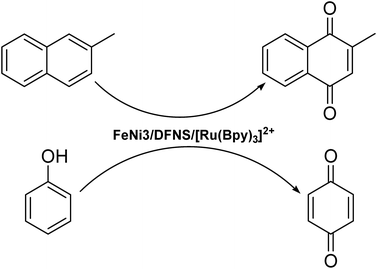
In the present study, a Ru(II) trisbipyridine complex is introduced into the fiber core of DFNS and used in the oxidation of phenols and production of vitamin K3. This new material has high hydrothermal stability, high surface area, and large pore volume. In addition, it shows dramatically greater catalytic activity as well as a greatly enhanced lifetime in comparison with amorphous SiO2 in the selective oxidation of phenols to 1,4-benzoquinones under moderate conditions, as seen in Scheme 2.
Experimental
Materials and methods
High purity chemicals were procured from Fluka and Merck. 2,3,6-Trimethylphenol (95%), 2,3,5-trimethylphenol (99%), 3,5-dimethylphenol (>99%), 2,6-dimethylphenol (99%), 2-methylphenol (>99%), 3-methylphenol (99%), 2-methoxyphenol (98%), 2-tert-butylphenol (99%), 2-fluorophenol (98%), 2-chlorophenol (>99%) and 2-iodophenol (98%) were obtained from Merck. The Electrothermal 9100 apparatus was utilized for the determination of uncorrected melting points in open capillaries. A VERTEC 70 spectrometer (Bruker) in transmission mode was used for the determination of Fourier-transform infrared (FTIR) spectra. Samples were pulverized and pelleted with spectroscopic grade KBr. Determination of size and structure of nanoparticles was done using transmission electron microscopy (TEM; Phillips CM10) operated at 100 kV. The crystallographic structures of nanoparticles were determined using powder X-ray diffraction (Bruker D8 Advance model) with Cu kα radiation. Thermal gravimetry analysis (TGA) (NETZSCH STA449F3) was utilized under nitrogen atmosphere with a heating rate of 10 °C min−1. 1H and 13C NMR spectra were determined with a Bruker DRX-300 AVANCE spectrometer and a Bruker DRX-400 AVANCE spectrometer. The NMR spectra for the two elements were recorded at 300.13 and 75.46 MHz, and 400.22 and 100.63 MHz, respectively. A Heraeus CHN-O-Rapid analyzer was used to perform elemental analyses for carbon, hydrogen and nitrogen. Thin-layer chromatography (TLC) was performed on silica gel polygramSILG/UV 254 plates and used for the determination of product purity and for monitoring reactions. A Shimadzu GCMS-QP5050 mass spectrometer was used to record the mass spectra.Total approach for the synthesis of FeNi3 MNPs
The procedure for the preparation of FeNi3 magnetic nanoparticles (MNPs) involved dissolving 0.01 mol FeCl2·4H2O and 0.03 mol NiCl2·6H2O in 300 mL of distilled water and the subsequent addition of 1.0 g of polyethylene glycol (PEG, MW 6000). To achieve the pH range of 12 ≤ pH ≤ 13, sodium hydroxide (NaOH) was added to the solution. Next, hydrazine hydrate (N2H4·H2O) at 80% concentration was added to the suspension in varied quantity. The suspension was left to react continuously for 24 h at room temperature. The pH of the suspension was maintained at 12 ≤ pH ≤ 13 with periodic dosing of NaOH. After that, the solid phase of the resultant mixture was filtered out to obtain black FeNi3 MNPs and rinsed with ionized water multiple times.42Total approach for the synthesis of FeNi3/SiO2 MNPs
An aqueous solution containing 80 mL of ethanol, 20 mL of deionized water and 2.0 mL of 28 wt% concentrated ammonia aqueous solution (NH3·H2O) was prepared. FeNi3 MNPs (0.02 mol) were dispersed in the mixture and 0.20 g of tetraethyl orthosilicate (TEOS) was added subsequently. The mixture was vigorously stirred for 24 h. The solid phase of the resultant mixture was filtered off and washed several times before being dried in atmospheric conditions at 60 °C.42Total approach for the synthesis of FeNi3/DFNS MNPs
Solution A was prepared as 30 mL of aqueous solution containing 0.3 g urea and a dispersion of 0.25 g of FeNi3/SiO2. The mixture was placed in an ultrasonic bath for 1 h. Solution B was prepared by adding 0.5 g cetylpyridinium bromide (CPB) into 0.75 mL of n-pentanol and 30 mL of cyclohexane. Solution A and solution B were mixed and stirred at room temperature, and 1.25 g TEOS was added in a dropwise manner. The mixture was continuously stirred for 1 h at room temperature and placed in an oven at 120 °C for 5 h to incite reaction. The completed reaction was cooled to room temperature before applying strong magnetic force for the isolation of FeNi3/DFNS core–shell microspheres. The solid phase was then washed several times with water and acetone. The washed solid was dried in a drying oven at 40 °C overnight and calcined at 550 °C for 5 h in atmospheric conditions.42Total approach for the synthesis of FeNi3/DFNS/3-bromopropyl MNPs
FeNi3/DFNS (200 mg) was mixed via ultrasonication with 20 mL of THF followed by the addition of 20 mmol of NaOH. After that, 22 mmol of 3-bromopropyl trimethoxysilane was added into the mixture at room temperature and stirred for 16 h at 50 °C. The resultant mixture was filtered and washed with ethanol and deionized water. The filtered solids were then dried under vacuum at 50 °C for 3 h.Total approach for the synthesis of FeNi3/DFNS/Bpy MNPs
FeNi3/DFNS/3-bromopropyl (200 mg) was diffused into a solution (80 mL) of ethanol, deionized water (20 mL) and 28 wt% concentrated aqueous ammonia (NH3·H2O, 2.0 mL) and finally 20 mmol of 2,2′-bipyridinyl-4,4′-diol was added. After intense stirring, the suspension produced was filtered and washed repeatedly several times, and then dried at a temperature of 50 °C in the presence of air.Total approach for the synthesis of FeNi3/DFNS/[Ru(Bpy)3]2+ MNPs
3.0 mg of RuCl3·3H2O and 70 mg of FeNi3/DFNS/Bpy (0.041 mmol) were dissolved into a wet DMF/EtOH 4/1 (10 mL) solution and the reaction mixture was heated to 70 °C for 72 hours. The reaction mixture was cooled to room temperature and concentrated under vacuum. The residue was dissolved in CH2Cl2 and also washed with distilled water. A saturated solution of 10 mL NH4PF6 was added and the solid obtained was separated out by using an external magnet. After that it was dried under vacuum.Total approach for oxidation of phenol
The selected phenol (1 mmol) and 10 mg of FeNi3/DFNS/[Ru(Bpy)3]2+ MNPs in 10 mL of acetonitrile/water 100/8 (v/v) were placed in a flask which was then charged with pure oxygen at a pressure of 2 MPa. The mixture obtained was stirred at a temperature of 40 °C for 1 hour. The solution was diluted with ethyl acetate after the reaction was complete. The catalyst was separated out using an external magnet. The obtained solution was dried using sodium sulfate. Then, the excess solvent was removed under reduced pressure to provide the respective 1,4-benzoquinone. The substrate conversions and product yields were quantified by gas chromatography (GC) using biphenyl as the internal standard. Each experiment was reproduced at least three times. The experimental error in the determination of the substrate conversions and product yields normally did not exceed 2%.Total approach for the synthesis vitamin K3
2-Methyl naphthalene (10 mmol) compound, 2 mL glacial acetic acid, and 0.1 mL H2O2 as well as 1 mg FeNi3/DFNS/[Ru(Bpy)3]2+ MNPs were stirred while being heated under reflux in 20 mL acetonitrile for around 8 hours. The catalyst was separated out using an external magnet. Solvent evaporation of the filtrate at decreased pressure provided the crude product. Vitamin K3 was isolated using GC on silica gel, eluted with petroleum ether/EtOAc (3![[thin space (1/6-em)]](https://www.rsc.org/images/entities/char_2009.gif) :
:![[thin space (1/6-em)]](https://www.rsc.org/images/entities/char_2009.gif) 1).
1).
Results and discussion
In the present work, magnetic DFNS solution was produced according to reported methods and reacted with 3-bromopropyl trimethoxysilane, followed by reductive amination to make the corresponding co-immobilized [Ru(Bpy)3]2+. This process can be observed in Scheme 3.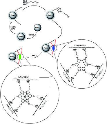 | ||
| Scheme 3 The process of co-immobilization of [Ru(Bpy)3]2+ on 3-bromopropyl trimethoxysilane functionalized FeNi3/DFNS nanoparticles. | ||
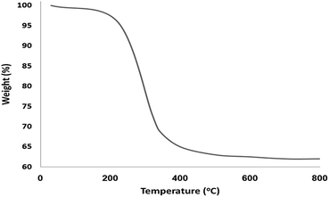
The morphology and the physical structure of FeNi3/DFNS and FeNi3/DFNS/[Ru(Bpy)3]2+ MNPs were analysed with field-emission scanning electron microscopy (FESEM) and TEM (Fig. 1). As shown in Fig. 1a and c, the FeNi3/DFNS possesses a core FeNi3 particle, a nonporous silica layer and silica fibres, and the samples comprise spheres of uniform size with diameters of ∼300 nm with a wrinkled radial structure. Scrutiny of TEM and FESEM images indicated that the FeNi3/DFNS/[Ru(Bpy)3]2+ consists of dendrimeric fibers with thicknesses of 5–8 nm ordered in three dimensions to create walls, which can allow straightforward access to the large surface area available. From FESEM and TEM analyses of FeNi3/DFNS/[Ru(Bpy)3]2+ MNPs, it can be seen that this arrangement is not altered after changing the morphology of the MNPs (Fig. 1b and d). Fig. 2 demonstrates the TGA of FeNi3/DFNS/[Ru(Bpy)3]2+ MNPs. The removal of the solvent chemisorbed and physisorbed on the surface of the FeNi3/DFNS/[Ru(Bpy)3]2+ material led to weight loss. In addition, weight loss of almost 29.1 wt% in the range 250–450 °C was related to the organic group derivatives. The reduction in weight at this range of temperature can be rationalized as being due to oxidation of ruthenium(II) complexes. In fact, the residual mass after the decomposition of FeNi3/DFNS/[Ru(Bpy)3]2+ MNPs is due to the vacated FeNi3/DFNS NPs.
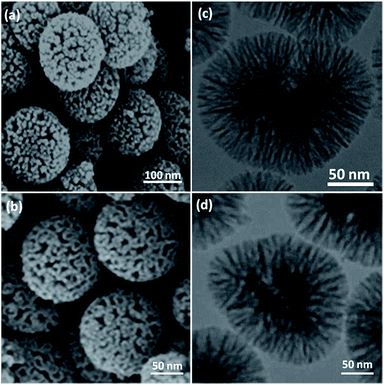 | ||
| Fig. 1 FESEM images of FeNi3/DFNS MNPs (a) and FeNi3/DFNS/[Ru(Bpy)3]2+ MNPs (b); TEM images of FeNi3/DFNS MNPs (c) and FeNi3/DFNS/[Ru(Bpy)3]2+ MNPs (d). | ||
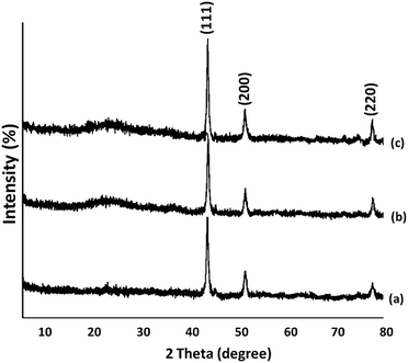
The X-ray diffraction patterns for FeNi3, FeNi3/DFNS, and FeNi3/DFNS/[Ru(Bpy)3]2+ MNPs are shown in Fig. 3. All spectra have in common the (111), (200), and (220) diffraction peaks in proper accord with the information in JCPDS card no. 19-0629 for the FeNi3 component of the samples (Fig. 3a). In addition to these iron oxide peaks, the XRD patterns of nanoparticles of the FeNi3/DFNS core–shell contained a wide peak at low diffraction angle that related to amorphous silica (as can be seen in Fig. 3b). Fig. 3c shows an XRD pattern for the FeNi3/DFNS/[Ru(Bpy)3]2+ MNPs that was unchanged from that of FeNi3/DFNS.
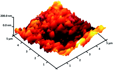
The FeNi3/DFNS/[Ru(Bpy)3]2+ MNPs surface roughness was investigated by atomic force microscopy (AFM). Fig. 4 shows the topographic picture for FeNi3/DFNS/[Ru(Bpy)3]2+ MNPs. As can be observed in Fig. 4, the highest regions, indicated by the brighter yellowish white color, were enhanced by decreasing T/W, suggesting an increase in the roughness of the catalyst surface.
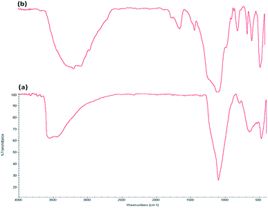
The FTIR spectra demonstrate the presence of silanols, phosphate groups, and hydroxyl organic groups in both FeNi3/DFNS MNPs (Fig. 5a) and FeNi3/DFNS/[Ru(Bpy)3]2+ MNPs (Fig. 5b). In the case of FeNi3/DFNS the wide absorption zones at 1099 and 3561 cm−1 are ascribed to Si–O–Si asymmetric stretching and OH respectively. Two peaks at 799 and 467 cm−1 are present in Fig. 5a, for Si–O–Si symmetrical stretching and bending, respectively. These peaks show the linkage of [Ru(Bpy)3]2+ onto the surface of FeNi3/DFNS. The composite FeNi3/DFNS/[Ru(Bpy)3]2+ shows bands at 1195, 799 and 467 cm−1. In the 3000–3550 cm−1 range, a strong and wide absorption band can be seen, which corresponds to –OH stretching vibrations. The peaks at 3120 and 2980 cm−1 that can be observed in Fig. 5b are due to stretching of the aromatic and aliphatic carbon-hydrogen bonds.
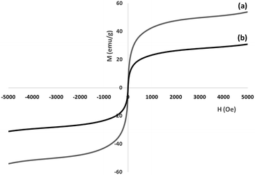
Vibrating sample magnetometry (VSM) was used for the determination of the nanoparticles' magnetic properties, with the magnetization curves of the obtained nanocomposite recorded at 300 K. In Fig. 6, it is shown that no residual magnetism is detected, thus paramagnetic characteristics are exhibited by the nanocomposites. Saturation magnetization values of 53.8 and 24.1 emu g−1 were determined for FeNi3 and FeNi3/DFNS/[Ru(Bpy)3]2+ MNPs, respectively. Responsivity towards an external magnetic field and the ability for quick redispersion upon removal of the magnetic field are characteristic of paramagnetic nanocomposites with high magnetization values. The resultant nanocomposite exhibited good magnetic responsivity, suggesting potential application for targeting and separation.
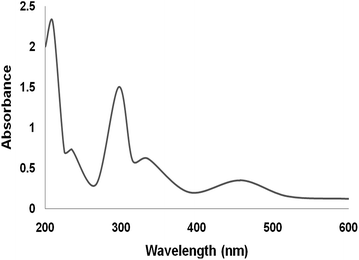
The UV-vis spectra of neat complex and the supported Ru(II) catalysts are given in Fig. 7. The spectra of the supported ruthenium catalysts showed features similar to those of the neat complex. The bands at 210 and 325 nm can be attributed to the charge transfer transition of salen ligand. The band at 475 nm is due to ligand-to-metal charge transfer transition of Ru(II) salen complex. On immobilization of Ru salen complex, all the characteristic bands appeared in its spectra. The UV-vis spectra confirmed the immobilization of Ru salen complex on the supports.
The Brunauer–Emmett–Teller (BET) nitrogen physisorption analysis showed that the specific surface areas of FeNi3/DFNS and FeNi3/DFNS/[Ru(Bpy)3]2+ are around 721, and 403 m2 g−1, respectively. The lower surface area of FeNi3/DFNS/[Ru(Bpy)3]2+ compared with FeNi3/DFNS may be due to the [Ru(Bpy)3]2+. Fig. 8 indicates the nitrogen adsorption as well as desorption isotherms of FeNi3/DFNS supported catalysts. The compound FeNi3/DFNS shows a type IV isotherm and also a hysteresis loop of H1-type which suggests the presence of mesopores. The pore size estimated using the desorption section of the nitrogen isotherm using the Barrett–Joyner–Halenda (BJH) method showed a narrow pore distribution peaking at around 11 nm for FeNi3/DFNS (see Table 1). The large mesopore amount of FeNi3/DFNS along with its high capacity can accomodate [Ru(Bpy)3]2+, which possesses a comparatively big molecular size.
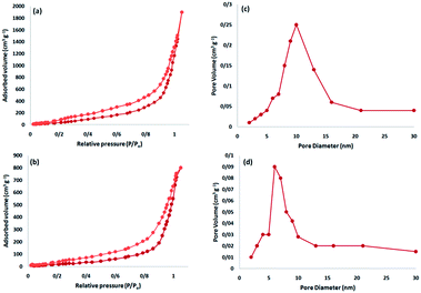 | ||
| Fig. 8 Adsorption–desorption isotherms of the FeNi3/DFNS NPs (a), and FeNi3/DFNS/[Ru(Bpy)3]2+ (b); and BJH pore size distributions of the FeNi3/DFNS NPs (c), and FeNi3/DFNS/[Ru(Bpy)3]2+ MNPs (d). | ||
| Catalyst | SBET (m2 g−1) | Va (cm3 g−1) | DBJH (nm) |
|---|---|---|---|
| FeNi3/DFNS | 721 | 3.7 | 11 |
| FeNi3/DFNS/[Ru(Bpy)3]2+ | 403 | 2.9 | 7 |
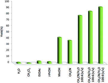
Different solvents were examined for the oxidation of phenol in the presence of FeNi3/DFNS/[Ru(Bpy)3]2+ MNPs, with the outcomes indicated in Fig. 9. Usual solvents such as ethyl acetate, water, isopropanol, and dichloromethane had no influence on the reaction. Methanol as a solvent produced a higher yield than did acetonitrile. It is important to note that though no reaction occurred in water, mixing water with acetonitrile caused a considerable enhancement in the production of 1,4-benzoquinone. The yield of 1,4-benzoquinone obtained was close to 93% in a mixture of acetonitrile and water. No 1,2-benzoquinone or chlorophenol was made in this reaction (only different unidentified compounds). The product yield was enhanced from 79% to 93% when the volume of water was increased from 4 to 8 mL (CH3CN/H2O [100![[thin space (1/6-em)]](https://www.rsc.org/images/entities/char_2009.gif) :
:![[thin space (1/6-em)]](https://www.rsc.org/images/entities/char_2009.gif) 8 (v/v)]).
8 (v/v)]).
As can be observed in Table 2, the optimum temperature required for performing the reaction was investigated. After studying various temperatures, it was found that 40 °C was the most appropriate temperature for this reaction. Temperatures higher than around this did not increase production. Although increasing the temperature promoted the reaction, serious side-reactions occurred at over 40 °C. Another factor that can be examined for the demonstrated reaction is the amount of FeNi3/DFNS/[Ru(Bpy)3]2+ MNPs to be used. The reaction was performed at 2 h at the temperature of 40 °C, in the presence of catalyst (8, 10, 12, and 14 mg). As can be seen in Table 2, in the absence of catalyst, no 1,4-benzoquinone was produced. Using different amounts of FeNi3/DFNS/[Ru(Bpy)3]2+ MNPs as catalyst led to variation in yield. The reaction using 8 mg of catalyst produced an 80% yield after 2 h duration. Increasing the amount of catalyst to 10 mg increased the yield of 1,4-benzoquinone to about 93%. Amounts of FeNi3/DFNS/[Ru(Bpy)3]2+ MNPs higher than 10 mg did not further increase the yield. Entries 6, 9 and 10 indicate the effects of time. The product yield increased on changing the reaction time from 0.5 h to 1 h. In addition, Table 2 indicates the influences of oxygen pressure. The yield of 1,4-benzoquinones was highly enhanced when oxygen pressure was increased from 0.5 bar to 2.0 bar owing to the increased oxygen concentration in the reaction mixture. By increasing the oxygen pressure to 3.5 bar, the phenol concentration is diluted and the reaction activity decreased.
| Entry | Temperature (°C) | Catalyst (mg) | Time (h) | O2 pressure (MPa) | Yielda (%) |
|---|---|---|---|---|---|
| a Isolated yield. | |||||
| 1 | r.t. | 14 | 2 | 3.0 | — |
| 2 | 30 | 14 | 2 | 3.0 | 71 |
| 3 | 40 | 14 | 2 | 3.0 | 93 |
| 4 | 50 | 14 | 2 | 3.0 | 93 |
| 5 | 40 | 12 | 2 | 3.0 | 93 |
| 6 | 40 | 10 | 2 | 3.0 | 93 |
| 7 | 40 | 8 | 2 | 3.0 | 80 |
| 8 | 40 | — | 2 | 3.0 | — |
| 9 | 40 | 10 | 1 | 3.0 | 93 |
| 10 | 40 | 10 | 0.5 | 3.0 | 39 |
| 11 | 40 | 10 | 1 | 0.5 | 11 |
| 12 | 40 | 10 | 1 | 1 | 52 |
| 13 | 40 | 10 | 1 | 1.5 | 81 |
| 14 | 40 | 10 | 1 | 2.0 | 93 |
| 15 | 40 | 10 | 1 | 2.5 | 93 |
| 16 | 40 | 10 | 1 | 3.5 | 91 |
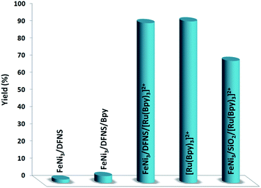
In order to study the performance of the catalyst, various control experiments were done; the data obtained are presented in Fig. 10. Firstly, the reaction was performed using FeNi3/DFNS, and it was found that none of the favorable product was made in 1 h reaction time. In addition, when FeNi3/DFNS/Bpy was utilized as the catalyst, a reaction could not be seen. The Bpy cannot catalyze the reaction under moderate reaction conditions. Following these negative results, we carried on the investigation to enhance the amount of product by adding the ruthenium(II). It is important to note that there is not a high variation between the yields obtained when the reaction was performed with FeNi3/DFNS/[Ru(Bpy)3]2+ MNPs and [Ru(Bpy)3]2+ catalyst, but [Ru(Bpy)3]2+ is not reusable. These results prove that the reaction is basically catalyzed using [Ru(Bpy)3]2+ functional groups within the nanostructure of FeNi3/DFNS. The nano-sized particles increase the presented surface of the active catalyst, therefore increasing the contiguity between catalyst and reactants, mimicking homogeneous catalysts. Nanoparticles of FeNi3/DFNS/[Ru(Bpy)3]2+ were utilized in the subsequent studies due to their appropriate high selectivity, reactivity, and easy separation. In addition, the activity and selectivity of the nano-catalyst may be managed by tailoring chemical and physical characteristics such as composition, shape, and size, as well as morphology. To investigate the exact effect of the presence of DFNS in the catalyst, the MNPs of FeNi3/DFNS/[Ru(Bpy)3]2+ were compared with FeNi3/SiO2/[Ru(Bpy)3]2+ MNPs, which possess identical compositions but distinct structures. When FeNi3/SiO2/[Ru(Bpy)3]2+ was utilized as the catalyst, the yield of the desired product was near to the mean value; however, the product for FeNi3/DFNS/[Ru(Bpy)3]2+ was better.
Different phenols were tested, and the outcomes are presented in Table 3. Generally, the reactivity of phenols depended on the number of alkyl groups in the benzene ring. Full conversion of 2,3,5,6-tetramethylphenol to yield 95% tetramethyl-1,4-benzoquinone was obtained at a temperature of 25 °C and a pressure of 2.0 bar for 1 hour. When 3,5-dimethylphenol was utilized, 90% production of 2,6-dimethyl-1,4-benzoquinone was achieved. A yield of 85% was obtained for 2,6-dimethylphenol under identical conditions. For 2,3,6-trimethylphenol, 92% production of trimethyl-1,4-benzoquinone was achieved. A similar outcome (94% yield) was determined for 2,3,5-trimethylphenol under identical conditions. A yield of 91% tert-butyl-1,4-benzoquinone were found for 2-tert-butylphenol. Under the same conditions, 89% of 2-methoxyphenol was converted to methyl-1,4-benzoquinone. In experiments using phenols with electron-withdrawing groups, such as halogen, no reaction was observed even after prolonged time.
| Entry | Substrate | Product | Yield (%) |
|---|---|---|---|
| a Isolated yield. | |||
| 1 |  |
 |
95 |
| 2 |  |
 |
92 |
| 3 |  |
 |
94 |
| 4 |  |
 |
90 |
| 5 |  |
 |
85 |
| 6 |  |
 |
89 |
| 7 |  |
 |
87 |
| 8 |  |
 |
91 |
| 9 |  |
 |
89 |
| 10 |  |
 |
— |
| 11 |  |
 |
— |
| 12 |  |
 |
— |
| 13 |  |
 |
— |
The effect of various solvents for production of vitamin K3 was investigated. For polar protic solvents, like water, ethanol, methanol and isopropanol, none of the desired product was formed. Hence, the production of the cross-coupling is comparatively poor for polar aprotic solvents like CHCl3, DMF, DMSO and CH2Cl2 as well as EtOAc. In the present paper, it was determined that heating with acetonitrile is very effective compared with utilizing organic solvents and produces green conditions for vitamin K3 production (see Table 4).
| Entry | Solvent | Yieldb (%) |
|---|---|---|
| a Reaction conditions: 2-methyl naphthalene (10 mmol), glacial acetic acid (2 mL), H2O2 (0.1 mL) and FeNi3/DFNS/[Ru(Bpy)3]2+ MNPs (2 mg) were stirred together while being heated under reflux in solvent (20 mL) for 10 hours.b Isolated yields. | ||
| 1 | H2O | — |
| 2 | MeOH | — |
| 3 | EtOH | — |
| 4 | i-PrOH | — |
| 5 | Dioxane | — |
| 6 | n-Hexane | — |
| 7 | THF | 17 |
| 8 | Toluene | 61 |
| 9 | CH2Cl2 | 35 |
| 10 | CHCl3 | 38 |
| 11 | DMSO | 43 |
| 12 | CH3CN | 93 |
| 13 | EtOAc | 23 |
| 14 | DMF | 67 |
| 15 | Solvent-free | — |
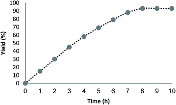
In this paper, the crucial role of temperature was investigated for vitamin K3 production in the presence of the MNPs of FeNi3/DFNS/[Ru(Bpy)3]2+ as catalyst. The most appropriate temperature in the case of this reaction was obtained by heating under reflux to improve the performance of the reaction. This indicated the catalytic activity is sensitive to the temperature of reaction. The amount of catalyst is a significant parameter in the considered reaction to obtain vitamin K3. No yield was obtained in the absence of the catalyst. When 0.2–0.8 mg of FeNi3/DFNS/[Ru(Bpy)3]2+ MNPs was used in this reaction, production of vitamin K3 was achieved under mild conditions. The best result was obtained when the model reaction was performed in the presence of 1 mg of FeNi3/DFNS/[Ru(Bpy)3]2+ MNPs. Further increasing the amount of catalyst did not enhance the yield in the model reaction (Fig. 11). Under the optimized conditions, GC (gas chromatography) was used to analyse the minimum reaction time necessary in the presence of FeNi3/DFNS/[Ru(Bpy)3]2+ MNPs (1 mg, showing that good yields of vitamin K3 may be obtained at 8 h Fig. 12).
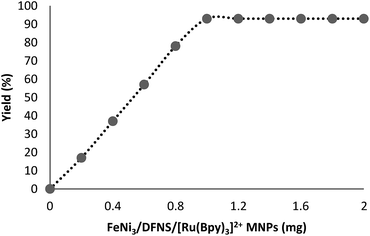 | ||
| Fig. 11 Effect of increasing amount of FeNi3/DFNS/[Ru(Bpy)3]2+ MNPs on the preparation of vitamin K3. | ||
We consider that the following hypothesis based on phenol is reasonable (Fig. 13): FeNi3/DFNS/[Ru(Bpy)3]2+ is oxidized by dioxygen as ruthenium(II), which oxidizes phenols to produce phenoxy radicals; the produced radical intermediates react with O2 to form 1,4-benzoquinone and H2O. Since phenol and o-mono-alkyl substituted phenols are inert, strong conditions such as higher temperature are required for the activation of the C–H bond in the para-position of these phenols. Because the radical intermediates of phenol and inert o-alkyl phenols produced during reaction are really active, a high pressure of dioxygen is necessary to keep dioxygen at a higher concentration in solution, which scavenges the intermediates to form the final products. That too high a pressure of dioxygen gives no clear improvement is evidence for this.
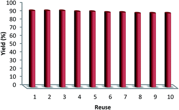
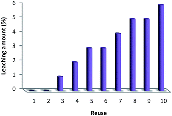
The reusability of a catalyst is a significant property in the case of green chemistry. Hence, the reusability of MNPs of FeNi3/DFNS/[Ru(Bpy)3]2+ was investigated under optimal conditions for the aerobic oxidation of phenol. After performing the reaction, the solid MNPs of FeNi3/DFNS/[Ru(Bpy)3]2+ were directly separated from the liquid reaction zone, magnetically, as when the reaction mixture is placed near a magnet, the solid readily separates from the solution in a few seconds. After cleaning with solvent, the catalyst can quickly be reused. Fig. 14 indicates the results of reusing the catalyst for 10 consecutive runs. The yield of product obtained was 90% at the tenth run, which means only a 3% drop in performance was seen in comparison with the fresh catalyst (93%). In addition, the amount of ruthenium leached into the solution for oxidation of phenol after each run was evaluated using ICP. The catalyst indicated very little leaching in each run: 0.6% metal leaching was discovered after the tenth run, so showing the durability of the catalyst under the reaction conditions, as illustrated in Fig. 15.
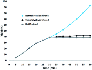
In addition, two studies were performed to clarify the heterogeneous nature of the catalyst. Firstly, we did a hot filtration experiment on the oxidation of phenol under optimum conditions and determined that around 39% of the catalyst was magnetically removed in situ after 30 min of reaction. In addition, the reactants were able to tolerate more reaction. The outcome was that, after the heterogeneous catalyst had been removed, the free catalyst remaining was feebly active, and a conversion of about 42% was obtained after 1 hour of the oxidation of phenol. This proved that the catalyst worked heterogeneously during the reaction and showed just slight leaching. Secondly, to confirm the heterogeneous form of the catalyst, mercury poisoning was additionally performed. Mercury(0) was used directly or synthesized in situ, and dramatically deactivated the metal catalyst on the active surface, so reducing the catalytic activity. The experiment conducted is proof of the heterogeneous nature of the catalyst. This test was performed with the aforesaid model reaction under optimal conditions. After 30 min of the reaction, about 300 molar mercury was released into the reaction mixture. The reaction mixture was stirred for more than 1 hour, during which period no further conversion was seen. The kinetic scheme of the reaction in the presence of Hg(0) is shown in Fig. 16. The negative outcomes obtained from both of the heterogeneity experiments (Hg(0) poisoning as well as hot filtration) suggested that the solid catalyst is really heterogeneous and no measurable ruthenium is leached upon oxidation of phenol.
Finally, we checked whether the structure of the recovered catalyst was maintained after 10 runs for the catalytic oxidation of phenol under the determined optimum conditions using EDX, XRD, VSM, TEM, and FESEM (Fig. 17). The UV-vis spectrum for the retrieved catalyst retained the attendant parameters, so vouching for the integrity of the catalyst within the reactions, as observed in Fig. 17a. As seen in Fig. 17b, the XRD pattern of the recovered catalyst proved that the catalyst structure remained totally intact during recycling. The catalyst sticks to the applied magnetic zone and can be easily prepared to be used again in the reaction mixture just like the fresh catalyst (Fig. 17c). It is worth noting that the nanocatalyst did not show any morphological changes in the TEM and FESEM images obtained from the recovered catalyst (Fig. 17d and e).
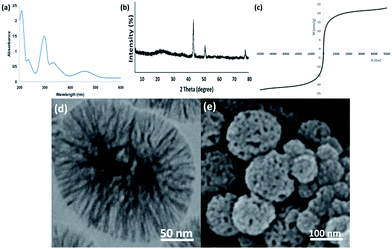 | ||
| Fig. 17 (a) EDX, (b) XRD, (c) VSM, (d) TEM, and (e) FESEM images of the recovered FeNi3/DFNS/[Ru(Bpy)3]2+ MNPs after the 10th run for oxidation of phenol. | ||
Conclusions
A very impressive hybrid catalyst was produced based on heterogeneous materials consisting of essentially different catalytic kinds. The hybrid catalyst was finely specified, and a complex formed by co-immobilization of ruthenium(II) on the FeNi3/DFNS fibers was demonstrated. FeNi3/DFNS/[Ru(Bpy)3]2+ showed appropriate catalytic activity in the case of phenol oxidation for synthesis of 1,4-benzoquinone derivatives as well as for eco-friendly production of vitamin K3. This green approach has some noteworthy eco-friendly properties, such as the simplicity of catalyst reclamation from the reaction mixture using a magnet, the use of molecular O2 as a non-toxic oxidant, and the synthesis of water as a by-product. Bio-catalysts (heterogeneous form) may improve the performance of the catalytic method in green organic synthesis, particularly accompanied by environmentally friendly solvents.Conflicts of interest
There are no conflicts to declare.Acknowledgements
This work was funded by the Zhejiang Provincial Natural Science Foundation of China (Grant No. LQ15E080007), the Jinhua Science and Technology Development Foundation of China (Grant No. 2018-3-002), and the Qianjiang College Natural Science Foundation of China (2019QJJL03).Notes and references
- H. Shekari, M. Sayadi, M. Rezaei and A. Allahresani, Surf. Interfaces, 2017, 8, 199–205 CrossRef CAS.
- A. Maity and V. Polshettiwar, ChemSusChem, 2017, 10, 3866–3913 CrossRef CAS.
- S. M. Sadeghzadeh, RSC Adv., 2015, 5, 68947–68952 RSC.
- U. Patil, A. Fihri, A. H. Emwas and V. Polshettiwar, Chem. Sci., 2012, 3, 2224–2229 RSC.
- V. Polshettiwar, J. ThivolleCazat, M. Taoufik, F. Stoffelbach, S. Norsic and J. M. Basset, Angew. Chem., Int. Ed., 2011, 50, 2747–2751 CrossRef CAS.
- A. Fihri, D. Cha, M. Bouhrara, N. Almana and V. Polshettiwar, ChemSusChem, 2012, 5, 85–89 CrossRef CAS.
- A. Fihri, M. Bouhrara, U. Patil, D. Cha, Y. Saih and V. Polshettiwar, ACS Catal., 2012, 2, 1425–1431 CrossRef CAS.
- C. Chao, Y. F. Zhao, H. J. Guan, G. X. Liu, Z. G. Hu and B. Zhang, Environ. Eng. Sci., 2017, 34, 762–770 CrossRef CAS.
- J. Su, J. J. Fu, Q. Wang, C. Silva and A. Cavaco-Paulo, Crit. Rev. Biotechnol., 2018, 38, 294–307 CrossRef CAS.
- D. M. Mate and M. Alcalde, Biotechnol. Adv., 2015, 33, 25–40 CrossRef CAS.
- J. R. Jeon and Y. S. Chang, Trends Biotechnol., 2013, 31, 335–341 CrossRef CAS.
- S. M. Sadeghzadeh, R. Zhiani and S. Emrani, New J. Chem., 2018, 42, 988–994 RSC.
- A. Das and S. S. Stahl, Angew. Chem., 2017, 56, 8892–8897 CrossRef CAS.
- K. Engström, E. V. Johnston, O. Verho, K. P. J. Gustafson, M. Shakeri, C. W. Tai and J. E. Bäckvall, Angew. Chem., 2013, 125, 14256–14260 CrossRef.
- B. S. Murray, M. V. Babak, C. G. Hartinger and P. J. Dyson, Coord. Chem. Rev., 2016, 306, 86–114 CrossRef CAS.
- C. S. Allardyce and P. J. Dyson, Dalton Trans., 2016, 45, 3201–3209 RSC.
- M. Hanif and C. G. Hartinger, Future Med. Chem., 2018, 10, 615–617 CrossRef CAS.
- A. A. Nazarov, C. G. Hartinger and P. J. Dyson, J. Organomet. Chem., 2014, 751, 251–260 CrossRef CAS.
- J. M. Gichumbi and H. B. Friedrich, J. Organomet. Chem., 2018, 866, 123–143 CrossRef CAS.
- A. D. Liang, J. Serrano-Plana, R. L. Peterson and T. R. Ward, Acc. Chem. Res., 2019, 52, 585–595 CrossRef CAS.
- R. Matheu, M. Z. Ertem, C. Gimbert-Surinach, X. Sala and A. Llobet, Chem. Rev., 2019, 119, 3453–3471 CrossRef CAS.
- P. Thangavel, B. Viswanath and S. Kim, Int. J. Nanomed., 2017, 12, 2749–2758 CrossRef CAS.
- J. Suriboot, H. S. Bazzi and D. E. Bergbreiter, Polymers, 2016, 8, 140 CrossRef.
- F.-A. Khan and G. Süss-Fink, Eur. J. Inorg. Chem., 2012, 727–732 CrossRef CAS.
- L. Wu, Y.-M. He and Q.-H. Fan, Adv. Synth. Catal., 2011, 353, 2915–2919 CrossRef CAS.
- L. Rosado Piquer, E. Jiménez Romero, Y. Lan, W. Wernsdorfer, G. Aromí and E. C. Sañudo, Inorg. Chem. Front., 2017, 4, 595–603 RSC.
- R. J. Holmberg, A.-J. Hutchings, F. Habib, I. Korobkov, J. C. Scaiano and M. Murugesu, Inorg. Chem., 2013, 52, 14411–14418 CrossRef CAS.
- W. Bonrath and T. Netscher, Appl. Catal., A, 2005, 280, 55–73 CrossRef CAS.
- W. Bonrath, M. Eggersdorfer and T. Netscher, Catal. Today, 2007, 121, 45–57 CrossRef CAS.
- N. N. Trukhan, A. Yu. Derevyankin, A. N. Shmakov, E. A. Paukshtis, O. A. Kholdeeva and V. N. Romannikov, Microporous Mesoporous Mater., 2001, 44–45, 603–608 CrossRef CAS.
- N. N. Trukhan, V. N. Romannikov, E. A. Paukshtis, A. N. Shmakov and O. A. Kholdeeva, J. Catal., 2001, 202, 110–117 CrossRef CAS.
- O. A. Kholdeeva, N. N. Trukhan, M. P. Vanina, V. N. Romannikov, V. N. Parmon, J. Mrowiec-Bialon and A. B. Jarzebski, Catal. Today, 2002, 75, 203–209 CrossRef CAS.
- H. Xin, L. Hu, J. Yu, W. Sun and Z. An, Catal. Commun., 2017, 93, 1–4 CrossRef CAS.
- L. Hu, J. Yu, H. Xin and Z. An, ChemistrySelect, 2017, 2, 949–952 CrossRef.
- S. Urus, M. Keles and O. Serindag, J. Inorg. Organomet. Polym., 2010, 20, 152–160 CrossRef CAS.
- S. Urus, M. Keles and O. Serindag, Phosphorus, Sulfur Silicon Relat. Elem., 2010, 185, 1416–1424 CrossRef CAS.
- J. Kowalski, J. Płoszynska and A. Sobkowiak, Catal. Commun., 2003, 4, 603–608 CrossRef CAS.
- E. Shimanskaya, V. Doluda, M. Sulman, V. Matveeva and E. Sulman, Chem. Eng. J., 2014, 238, 206–209 CrossRef CAS.
- D. Chadar, M. Camilles, R. Patil, A. Khan, T. Weyhermüller and S. Salunke-Gawali, J. Mol. Struct., 2015, 1086, 179–189 CrossRef CAS.
- O. A. Anunziata, A. R. Beltramone and J. Cussa, Appl. Catal., A, 2004, 270, 77–85 CrossRef CAS.
- M. Florea, R. S. Marin, F. M. Palasanu, F. Neatu and V. I. Pârvulescu, Catal. Today, 2015, 254, 29–35 CrossRef CAS.
- R. Zhiani, S. M. Saadati, M. Zahedifar and S. M. Sadeghzadeh, Catal. Lett., 2018, 148, 2487–2500 CrossRef CAS.
| This journal is © The Royal Society of Chemistry 2019 |

