
 Open Access Article
 This Open Access Article is licensed under a Creative Commons Attribution-Non Commercial 3.0 Unported Licence
Research on the thermal conductivity and dielectric properties of AlN and BN co-filled addition-cure liquid silicone rubber composites
Zhenzhen Ou,
Feng Gao,
Huaijun Zhao,
Shumeng Dang and
Lingjian Zhu *
*
Xi'an University of Technology, Xi'an 710048, Shaanxi, China. E-mail: zlj_zhy@xaut.edu.cn; Tel: +86-029-82312861
First published on 13th September 2019
Abstract
The present work aims at studying the thermal and dielectric properties of addition-cure liquid silicone rubber (ALSR) matrix composites using boron nitride (BN) and aluminum nitride (AlN) as a hybrid thermal conductive filler. Composite samples with different filler contents were fabricated, and the density, thermal conductivity, thermal stability, dielectric properties, and volume resistivity of the samples were measured. According to the experimental results, the density, thermal conductivity, dielectric constant and dielectric loss tangent values all increased with the increasing addition of filler. When the weight fraction of hBN filler was 50 wt%, the thermal conductivity of composites was 0.554 W (m−1 K−1), which is 3.4 times higher than that of pure ALSR. The corresponding relative permittivity and dielectric loss were 3.98 and 0.0085 at 1 MHz, respectively. Furthermore, TGA results revealed that the AlN/BN hybrid filler could also improve the thermal stability of ALSR. The volume resistivity of ALSR composites was higher than that of pure ALSR. The addition of fillers improved the thermal properties of ALSR and had little effect on its insulation properties. This characteristic makes ALSR composites attractive in the field of insulating materials.
1 Introduction
With the development of microelectronic integration technology and application under high frequency and high power conditions, electrical equipment is constantly becoming smaller, which causes the heat production per unit area of electronic equipment to increase rapidly.1–3 According to Bar-Cohen et al., the stability of electronic devices will decrease by 10% with every 2 °C increase in temperature.4 Therefore, effective dissipation of accumulated heat is important to ensure the stability and lifetime of the electronic equipment. The research on the thermal conductivity of electronic packaging materials is becoming more and more important. With the advantages of excellent electrical insulation, chemical resistance, weather resistance, hydrophobicity, low shrinkage and no by-product release during cross-linking, addition-cure liquid silicone rubber (ALSR) is thought to be a good packaging material in high-voltage electrical equipment, although it has low thermal conductivity (about 0.125–0.25 W (m−1 K−1)).5,6 At present, the thermal conductivity of polymers for electronic packaging is reinforced by filling with high thermal conductivity but electrically insulating particles,7,8 such as aluminum nitride (AlN),9 boron nitride (BN),10,11 silicon carbide (SiC),12 and alumina (Al2O3).13 There have been many studies on the influences of particle size and geometry, surface treatment and orientation of fillers on the thermal conductivity of polymer-based composites.14–17 For example, Liu et al. studied the effects of BN nanoplates as filler on the thermal diffusivity/conductivity, electrical breakdown strength, mechanical performance, dielectric behaviour, and hydrophobicity properties of high temperature vulcanized silicone rubber.18 It was reported that after adding BN nanoplates the thermal conductivity could be increased by 30%, the electrical breakdown strength and hydrophobicity were also improved. Aluminum nitride was added as thermal conductive filler at weight fractions of 16.67 wt%, 21.05 wt%, and 28.57 wt% to pristine silicone rubber in ref. 19. Thermal conductivity of all three aluminum nitride/silicone rubber composites were increased 27.9%, 41.4%, and 43.7% than that of the pristine silicone rubber. It has already been explored that the better performance can be achieved by using two or more traditional fillers. Kim et al. reported that the synergistic effect of spherical Al2O3 and BN nanoplatelets for efficient thermal transport in polymer composites.20 Addition of BN nanoplatelets boosted thermal conductivity of Al2O3-containing polymer composites up to 3.6 W (m−1 K−1) which was more than double the thermal conductivity of pristine polymer composites without BN nanoplatelets. Zha et al. focused on the effect of micro-Si3N4 and nano-Al2O3 mixture on thermal conductivity, dielectric and mechanical properties of the SR composites. With the addition of micro-Si3N4–nano-Al2O3 mixture at 30 vol% (Si3N4/Al2O3 = 26/4), the composites showed high thermal conductivity of 1.6 W (m−1 K−1), low relative dielectric permittivity of 5.3 and high breakdown strength of 85 MV m−1.21 However, the research on ALSR is mainly focused on its tracking resistance, flame retardancy22–24 and thermal degradation mechanism.25There are few studies on filling ceramic particles to improve the thermal conductivity of ALSR. In this work, commercially available boron nitride and aluminum nitride was investigated as the hybrid thermal filler to prepare ALSR composites. The synergistic effect of boron nitride and aluminum nitride on the thermal conductivity, thermal stability, breakdown strength, dielectric properties, and volume resistivity before and after thermal aging of the ALSR composites were investigated.
2 Materials and methods
2.1 Materials
Vinyl-terminated poly-dimethylsiloxane (Vi-PDMS, viscosity 1000 cSt and vinyl content 0.96 wt%), poly-hydromethylsiloxane (PHMS, viscosity 20–30 cSt and hydride content 0.3 wt%) were purchased from Zhejiang Xin'an Chemical Industry Group Co., Ltd., China. Platinum(0)-1,3-divinyl-1,1,3,3-tetramethyldisiloxane complex solution (Karstedt's catalyst, platinum content 3000 ppm), 1-ethynyl-1-cyclohexanol (inhibitor), and 3-aminopropyl triethoxysilane (KH550) were purchased from Shanghai Aladdin Biochemical Technology Co., Ltd., China.Hexagonal boron nitride (h-BN; thermal conductivity, 33 W (m−1 K−1); relative dielectric permittivity, 4.0; average sizes, 0.5 μm; density, 2.25 g cm−3; purity, 99.9%) and aluminium nitride (thermal conductivity, 240 W (m−1 K−1); relative dielectric permittivity, 4.0; average sizes, 10 μm; density, 3.26 g cm−3) were purchased from Ke Gong Metallurgy Material Co., China.
Absolute ethanol (purity, 99.7%) was obtained from Sinopharm Chemical Reagent Co., Ltd. (Shanghai, China). Distilled water was self-prepared in the laboratory.
2.2 Surface modification
Silane coupling agent KH550 was used to pre-treat the surfaces of the ALN and BN particles to ensure better dispersion and reduce thermal resistance of filler and matrix. At first, 0.75 g of KH-550 was mixed in 20 g of absolute ethanol, and mechanical stirrer was used to stir mixed solution to achieve sufficient hydrolysis of the coupling agent. Then, 50 g of ALN particles or BN particles were dispersed in 300 g of absolute ethanol by sonication for 60 min. After that, the hydrolysed coupling agent added dropwise to the mixed solution of filler and ethanol. The obtained mixture was put into a water bath at 80 °C and stirred with mechanical stirrer for 4 hours. Finally, the mixture was filtered and dried in a vacuum oven at 110 °C for 12 hours.2.3 Sample preparation
Vi-PDMS, PHMS, ALN, BN, 1-ethynyl-1-cyclohexanol and Karstedt's catalyst were sequentially mixed, using a mechanical stirrer with 700 rpm in rotation speed for 120 min. Among them, the molar ratio of Vi-PDMS to PHMS satisfied nSi-Vi![[thin space (1/6-em)]](https://www.rsc.org/images/entities/char_2009.gif) :nSi-H = 1:1.2 and the weight ratio of ALN to BN fillers in the composites were fixed at 8:2. After stirring, the mixture was poured into stainless steel molds and degassed until all air bubbles vanished. Finally, the moulds were kept in the vacuum oven at 120 °C for 120 minutes to achieve curing. The total fraction of the ALN and BN fillers in the composites was varied from 0 wt%, 10 wt%, 20 wt%, 30 wt%, 40 wt% and 50 wt%.
:nSi-H = 1:1.2 and the weight ratio of ALN to BN fillers in the composites were fixed at 8:2. After stirring, the mixture was poured into stainless steel molds and degassed until all air bubbles vanished. Finally, the moulds were kept in the vacuum oven at 120 °C for 120 minutes to achieve curing. The total fraction of the ALN and BN fillers in the composites was varied from 0 wt%, 10 wt%, 20 wt%, 30 wt%, 40 wt% and 50 wt%.
2.4 Characterization
The fracture surface morphology of the composites was observed by scanning electron microscopy (SEM, TESCAN MAIA3, Czech Republic) after being coated with gold.The density of AlN/BN/ALSR composites was measured by Archimedes principle. The specific measurement method is as follows: the mass of the sample in the air (m1) and in the distilled water (m2) were respectively measured at room temperature by using an analytical balance (precision, 0.1 mg; BSA124S, Sartorius, Germany), and the sample density could be calculated by the relation
| ρ = ρwm1/(m1 − m2) |
Based on the laser flash method, the thermal conductivity (λ) of the samples can be calculated:
| λ = α × Cp × ρ, |
Thermo gravimetric analysis (TGA) was conducted on Synchronous thermal analyser (STA449F5, NETZSCH, German). The weight of samples were 5–10 mg and temperature range was from 30 °C to 800 °C with a heating rate of 10 °C min−1.
The dielectric constant and dielectric loss of samples were measured using precision impedance analysers (WK6500B, Wayne Kerr, United Kingdom) and dielectric constant detector (S916, Shanghai Aiyi Electronic Equipment Co. Ltd., China) in the frequency range from 1 kHz to 1 MHz at the temperature of 25 °C.
The volume resistivity was measured using high resistance meter (ZC36, Shanghai Anbiao Electronics Co., Ltd., China) on DC voltage of 500 V, power frequency 50 Hz, temperature 25 °C. Thermal aging of the samples were carried out at 100 °C in an oven, and the aging times were 40 d, 70 d, 100 d, and 150 d.
3 Results and discussion
3.1 Density
Fig. 1 shows the density of at different filler contents. It can be seen that the density of the ALSR composites is improved with the increasing addition of AlN/BN fillers, which is mainly due to the higher density of the mixed filler than the pure silicone rubber. It is also apparent from Fig. 1 that the density of the ALSR composite is approximately linear with the content of the mixed filler. Furthermore, due to the higher porosity in composites with higher filler content, the increase of density tends to decrease with the increase of filler proportion.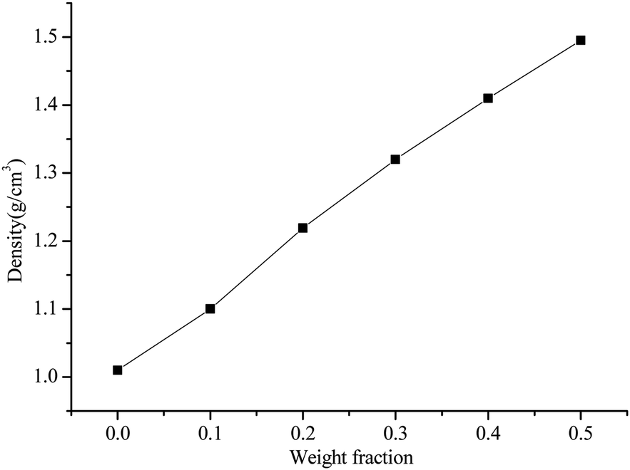 | ||
| Fig. 1 Density of AlN/BN/ALSR composites with different filler loading. | ||
3.2 Thermal conductivities of ALSR composites
The thermal conductivity coefficient for the AlN/BN/ALSR composites at different filler contents are shown in Fig. 2.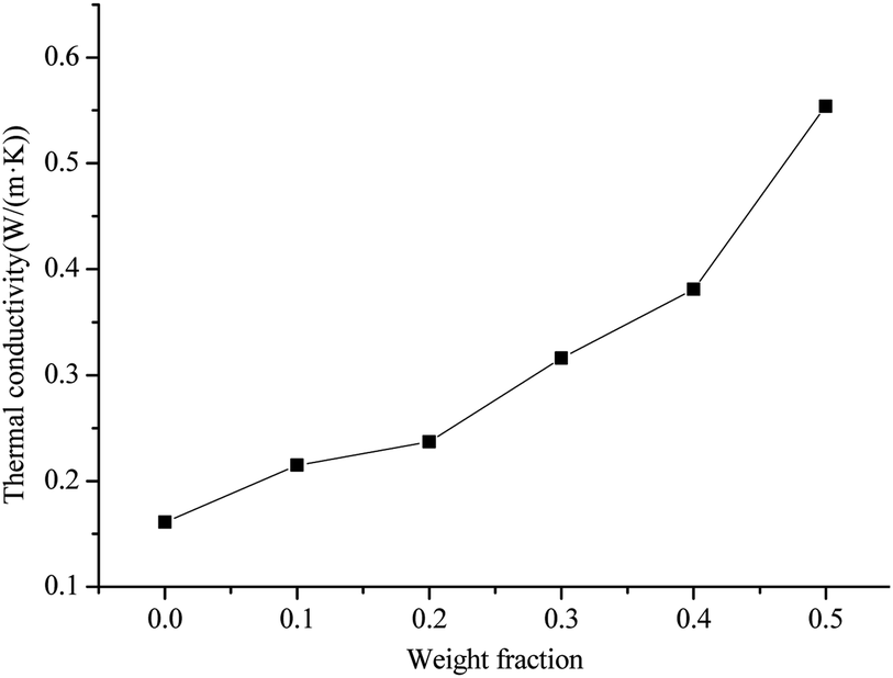 | ||
| Fig. 2 Thermal conductivity of AlN/BN/ALSR composites with different filler loading. | ||
It can be seen that thermal conductivity coefficient of AlN/BN/ALSR composites is effectively improved after the addition of the filler, and increases as the ALN/BN loading increases. It can also be observed that the thermal conductivity coefficient of the ALSR composite increases slowly when the AlN/BN hybrid filler loading is less than 20 wt%. The thermal conductivity of composites with 20 wt% AlN/BN loading is 0.237 W (m−1 K−1), which is only 1.48 times higher than that of pure ALSR (0.160 W (m−1 K−1)). The main reason for this phenomenon is that at low filler loading, AlN and BN particles are randomly dispersed within the ALSR matrix (Fig. 3(a)), and wrapped and separated by the ALSR matrix. The fillers are isolated from each other and do not form the heat conduction chain. The thermal conductivity of fillers does not contribute much to the thermal conductivity of ALSR composites.20,26 The thermal conductivity of the composite is mainly determined by the polymer matrix itself. After the AlN/BN filler content is higher than 20% by weight, the thermal conductivity begins to increase rapidly. The thermal conductivity of composites with 50 wt% AlN/BN loading is 0.554 W (m−1 K−1), which is 2.34 times higher than that of 20 wt% ALSR composites. This is because as the filler content increases, the possibility of touching and connection between the AlN/BN particles increases (Fig. 3(b) and (c)), and effective thermally conductive channels & networks of AlN/BN begins to form, resulting in a much reduced thermal contact resistance and rapid improvement of the thermal conductivity of AlN/BN/ALSR composites.
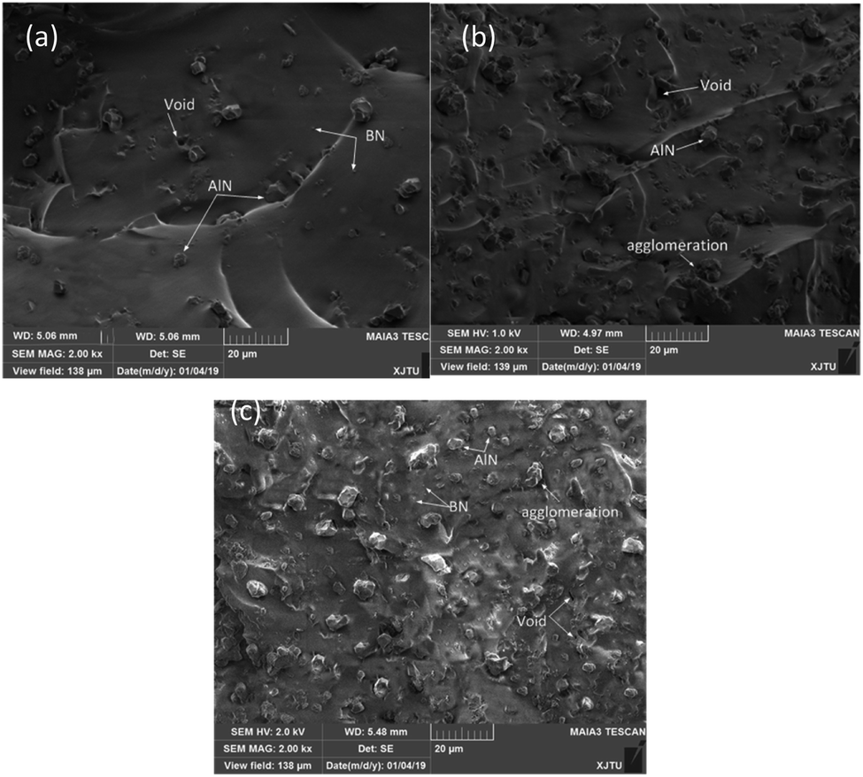 | ||
| Fig. 3 SEM images of the fractured cross-section of the AlN/BN/ALSR composites with (a) 10 wt% AlN/BN filled and (b) 30 wt% AlN/BN filled (c) 50 wt% AlN/BN filled. | ||
3.3 Thermal stability of ALSR composites
Thermal stability of the ALSR composites was investigated by thermal gravimetric analysis. The TGA and DTG curves of pure ALSR and ALSR composites under air atmosphere are shown in Fig. 4, and the characteristic data of those curves is shown in Table 1. As demonstrated, the thermal degradation of pure ALSR can be clearly divided into two stages. The first stage of thermal decomposition starts at about 312 °C, and the temperature for peak degradation is about 360 °C. The weight loss at this stage is mainly due to the oxidation of the methyl group in the ALSR chain, which initiates the melting and depolymerisation of the ALSR chain.27 The second stage starts at 405 °C and the temperature for peak degradation is about 495 °C. The weight loss at this stage is mainly attributed to the methyl groups broke away from the chains and the increased depolymerisation of the ALSR chain.28,29 When the temperature reached 800 °C, the residue amount of pure ALSR was 36.88%. For BN/AlN/ALSR composite, the thermal weight loss process can also be divided into two stages, and as the filler content increases, the limit between the two-stage thermal weight losses gradually decreases. Furthermore, the characteristic temperature of 5% weight loss (T5) of ALSR composites is slightly lower than that of pure ALSR, the mass loss of the first stage thermal decomposition increases, and the peak decomposition temperature of the second stage thermal decomposition decreases. There are three reasons for this phenomenon: (1) the addition of fillers affects the addition reaction of Vi-PDMS and PHMS, which reduces the polymerization degree and increases the vulcanized low molecular weight polymers;25 (2) the volatilization temperature of the solvent and adsorbed water brought by the filler is low; (3) the defects including voids and cracks caused by fillers and matrix may also have a negative impact on the thermal degradation process.10 At the same time, because the decomposition temperature and specific heat capacity of AlN and BN particles are higher than that of ALSR, the peak decomposition temperature of first stage of thermal decomposition of BN/AlN/ALSR composite is higher than that of pure ALSR, and the residual weight at 800 °C increases largely. In summary, the addition of fillers has both positive and negative effects. Compared to pure ALSR, the temperature at 5% weight loss is slightly lower, but the high temperature residue weight is significantly increased. And the T5 showed an upward trend with the increase of fillers. Therefore, the thermal stability of the BN/AlN/ALSR composite is improved at high temperatures as a whole.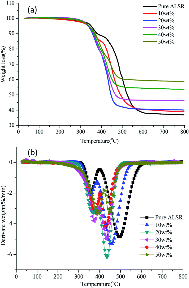 | ||
| Fig. 4 TGA (a) and DTG (b) curves of AlN/BN/ALSR composites with different filler content under air atmosphere. | ||
| Samples | Temperature for 5% weight loss T5 (°C) | Temperature for the first peak degradation T1max (°C) | Temperature for the second peak degradation T2max (°C) | Residual weight at 800 °C (wt%) |
|---|---|---|---|---|
| Pure ALSR | 350.74 | 360 | 495 | 36.88 |
| 10 wt% | 338.51 | 355 | 455 | 38.88 |
| 20 wt% | 336.73 | 366 | 435 | 40.00 |
| 30 wt% | 339.66 | 374 | 435 | 46.30 |
| 40 wt% | 341.20 | 378 | 427 | 53.64 |
| 50 wt% | 341.22 | 394 | 444 | 58.76 |
3.4 Dielectric properties of ALSR composites
The dependence of relative dielectric constant and dielectric loss on frequency of BN/AlN/ALSR composites at different filler content is shown in Fig. 5. The frequency range is from 1 kHz to 1000 kHz. From Fig. 5, it can be seen that the relative permittivity and dielectric loss of BN/AlN/ALSR composites increases with filler loading. This is because that for BN/AlN/ALSR composite, besides the dipole polarization of the rubber chain segments, the interfacial polarization caused by the addition of high dielectric constant fillers into the rubber matrix also enhances the relative permittivity and dielectric loss of the ALSR composites.30–32 Moreover, from Fig. 5(a), it is obviously that the relative permittivity of the composite samples does not show appreciable differences within the measured frequency range, since there is hardly any change in the polarization mechanism. It can also be observed in Fig. 5(b), the dielectric loss of samples decreases firstly and then increases with increasing frequency. The dielectric loss of ALSR composite mainly includes the conductance loss and relaxation polarization loss. When the measured frequency is low, the dipole polarization and the interface polarization can keep up with the change of the electric field, so the loss of relaxation polarization is small.33,34 The conductance loss caused by leakage current is the main loss. As the frequency increases, the conductance loss decreases inversely, but the relaxation polarization loss increases gradually because the dipole polarization and the interfacial polarization fail to catch up with the change cycle of the electric field. Therefore, dielectric loss increases gradually after a stable period of time. In summary, although the dielectric constant and dielectric loss of the composite sample increase with the increase of filler loading, the value is still low. Taking 50 wt% composite samples as an example, its dielectric constant is 4.0 and dielectric loss is 0.0085 at 1 MHz. Therefore, the ALSR composite can be used as encapsulation material for power electronic components.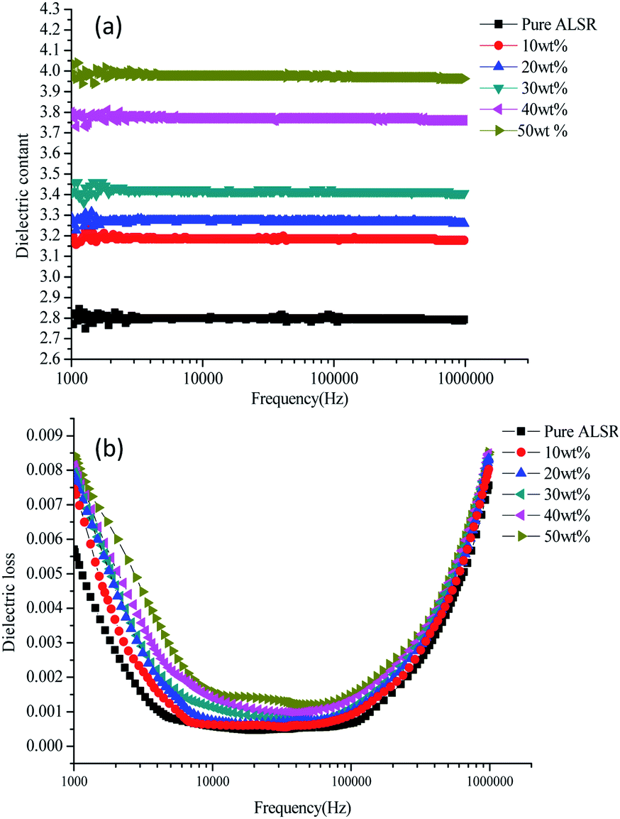 | ||
| Fig. 5 Dielectric constant (a) and dielectric loss (b) curves of AlN/BN/ALSR composites. | ||
3.5 Volume resistivity of ALSR composites
The volume resistivity of the polymer material mainly depends on the concentration, mobility and charge amount of carrier. The concentration of the movable carrier in the polymer composite is determined by the matrix itself, and the addition of the ceramic particles will not increase the movable load. The volume resistivity of the BN/AlN/ALSR composite before thermal aging as a function of the filler loading is shown in Fig. 6(a). It can be seen from Fig. 6(a) that the volume resistivity of the samples filled with BN/AlN filler is higher than that of pure ALSR, and increases first and then decreases as the BN/AlN filler loading increases. The volume resistivity of the ASLR composite increases as the filler loading is low, which can be attributed to a decrease in carrier mobility. There are two main reasons for the decrease of carrier mobility.35–37 One is that the BN/AlN filler adsorbs some carriers in ALSR, which reduces the number of carriers in the sample. Another is that the addition of fillers introduces a large number of traps between the interface of the filler and the rubber matrix. Then the movable carriers are trapped by the traps on the interface, which makes the carrier mobility decrease. As the filler loading increases, the interface regions between adjacent particles may overlap. Then a local conductive channel is formed and the movable carriers are transported along the conductive channel. After obtaining sufficient energy under the applied electric field, the barrier is jumped over to participation in conduction, resulting in a decrease in resistivity.38 With the increase of filling fraction, the change of carrier mobility becomes smaller and smaller, and the volume resistivity tends to be stable.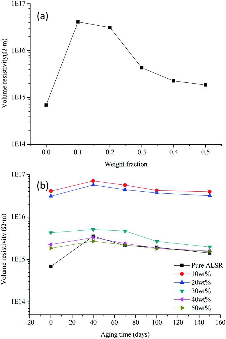 | ||
| Fig. 6 Volume resistivity before thermal aging (a) and after thermal aging (b) curves of AlN/BN/ALSR composites. | ||
The volume resistivity of the BN/AlN/ALSR composite after thermal aging as a function of the aging time is shown in Fig. 6(b). It can be seen from Fig. 6(b) that the volume resistivity of all samples increases first and then decreases with the increase of aging time. This is attributed to the fact that in the early stage of the thermal aging, the low molecular weight gradually precipitates under the action of heat, and the internal re-crosslinking reaction of the material predominates, resulting in a decrease in the number and mobility of carriers which would make an increase in volume resistivity.39 With the prolongation of thermal aging time, the degree of thermal degradation inside the composite material is gradually increased, leading to the breakage of the main chain, side chain, cross-linking bonds of ALSR, and the generation of a large number of free radicals and polar groups. This greatly increases the number and mobility of carriers, and significantly reduces the volume resistivity. It can also be seen from Fig. 6(b) that compared with the ALSR composites, the volume resistivity of pure ALSR varies most with thermal aging time. The ALSR composite sample, regardless of the filling amount of the inorganic filler, the volume resistivity does not change much with the thermal aging time. This may be because the thermal stability of the ALSR composites increases after the addition of the fillers, which inhibits the re-crosslinking reaction and the degradation reaction to a certain extent, so that the volume resistivity of the composite material does not change much with the thermal aging time.
4 Conclusions
In this research, AlN and BN co-filled ALSR with the purpose of being applied in insulation packaging of high voltage power electronic devices was studied, and the effects of the filling fraction of AlN and BN with a fixed weight ratio of 8:2 on various properties of the composites were discussed. The main conclusions are as follows.
The thermal conductivity of AlN/BN/ALSR composites increase with the filler content increase, the maximum value can reach 3.4 times of pure ASLR. The TGA results reveal that although the temperature of 5% weight loss is slightly lower than that of pure ALSR, the residual amount is greatly increased at 800 °C. Therefore, the overall thermal stability has increased slightly.
The volume resistivity of AlN/BN/ALSR composites before thermal aging increases first and then decreases with the increase of filler content, and is higher than that of pure ALSR. The volume resistivity of AlN/BN/ALSR composites after thermal aging increases first and then decreases with the increase of aging time, and pure ALSR varies the most than that of ALSR composites.
The dielectric constant and dielectric loss of AlN/BN/ALSR composites increases with the increase of filler loading. The dielectric constant of 3.98 and dielectric loss of 0.0085 is obtained for 50 wt% of AlN/BN/ALSR composites at 1 MHz, which satisfies the applications in the field of insulation packaging.
Conflicts of interest
There are no conflicts to declare.Acknowledgements
This work was supported by the National Science and Technology Major Project of the Ministry of Science and Technology of China (No. 2017YFF0104403).References
- R. Heiderhoff, A. Makris and T. Riedl, Mater. Sci. Semicond. Process., 2016, 43, 163–176 CrossRef CAS.
- H. Chen, V. V. Ginzburg, Y. Jian, Y. Yang, L. Wei, H. Yan, L. Du and B. Chen, Prog. Polym. Sci., 2016, 59, 41–85 CrossRef CAS.
- Z. Pan, S. Rui, S. Zhu, Y. Kang, B. Huang and L. Zhu, J. Adhes. Sci. Technol., 2018, 32, 1–14 CrossRef.
- A. Bar-Cohen, A. Kraus and S. Davidson, Mech. Eng., 1983, 105, 53–59 Search PubMed.
- C.-C. Kuo and J.-X. Lin, Int. J. Adv. Manuf. Technol., 2019, 101, 615–625 CrossRef.
- E. Delebecq and F. Ganachaud, ACS Appl. Mater. Interfaces, 2012, 4, 3340–3352 CrossRef CAS.
- C. Huang, Q. Xin and R. Yang, Mater. Sci. Eng., R, 2018, 132, 1–22 CrossRef.
- C. Yu, J. Zhang, T. Wei and D. F. Xiao, RSC Adv., 2018, 8, 21948–21967 RSC.
- Y. Ying, Z. Chi, B. Tang, E. Li and S. Zhang, J. Mater. Sci.: Mater. Electron., 2018, 29, 14890–14896 CrossRef.
- J. Gu, X. Meng, Y. Tang, L. Yang, Z. Qiang and K. Jie, Composites, Part A, 2017, 92, 27–32 CrossRef CAS.
- T. Huang, X. Zeng, Y. Yao, R. Sun, F. L. Meng, J. B. Xue and C. P. Wong, RSC Adv., 2017, 7, 23355–23362 RSC.
- S. Na, H. Pan, X. Hou, S. Cui, L. Shi and D. Peng, RSC Adv., 2017, 7, 46306–46312 RSC.
- Z. Wang, Y. Cheng, H. Wang, M. Yang, Y. Shao, X. Chen and T. Tanaka, J. Mater. Sci., 2017, 52, 4299–4308 CrossRef CAS.
- G. Duan, Y. Wang, J. Yu, J. Zhu and Z. Hu, Front. Mater. Sci., 2019, 13, 64–76 CrossRef.
- Y. Guo and S. N. Leung, Mater. Chem. Phys., 2018, 214, 221–228 CrossRef CAS.
- R. Seokgyu, O. Taeseob and K. Jooheon, RSC Adv., 2018, 8, 22846–22852 RSC.
- D. Kuscer, I. Bantan, M. Hrovat and B. Malič, J. Eur. Ceram. Soc., 2017, 37, 739–746 CrossRef CAS.
- P. Liu, L. Li, L. Wang, T. Huang, Y. Yao and W. Xu, J. Alloys Compd., 2019, 774, 396–404 CrossRef CAS.
- L. K. Namitha, S. Ananthakumar and M. T. Sebastian, J. Mater. Sci.: Mater. Electron., 2015, 26, 891–897 CrossRef CAS.
- Y. K. Kim, J. Y. Chung, J. G. Lee, Y. K. Baek and P. W. Shin, Composites, Part A, 2017, 98, 184–191 CrossRef CAS.
- J. Zha, Z. Dang, W. Li, Y. Zhu and G. Chen, IEEE Trans. Dielectr. Electr. Insul., 2014, 21, 1989–1996 CAS.
- J. Qiu, X. Lai, W. Fang, H. Li and X. Zeng, Polym. Degrad. Stab., 2017, 144, 176–186 CrossRef CAS.
- Y. Li, X. Zeng, X. Lai, H. Li and W. Fang, Polym. Test., 2017, 63, 92–100 CrossRef CAS.
- A. R. Verma and B. S. Reddy, IEEE Trans. Dielectr. Electr. Insul., 2018, 25, 46–52 CAS.
- W. Fang, X. Zeng, X. Lai, H. Li, C. Xie, W. Chen and Y. Zhang, IEEE Trans. Dielectr. Electr. Insul., 2017, 23, 3668–3675 Search PubMed.
- S. He, J. Hu, C. Zhang, J. Wang, L. Chen, X. Bian, J. Lin and X. Du, Polym. Test., 2018, 67, 295–301 CrossRef CAS.
- E. Delebecq, S. Hamdani, J. Raeke, J. M. Lopez and F. Ganachaud, ACS Appl. Mater. Interfaces, 2011, 3, 869–880 CrossRef CAS.
- C. Xie, X. Zeng, W. Fang, X. Lai and H. Li, Polym. Degrad. Stab., 2017, 142, 263–272 CrossRef CAS.
- G. Camino, S. M. Lomakin and M. Lazzari, Polymer, 2001, 42, 2395–2402 CrossRef CAS.
- M. T. Nazir, T. Phung, M. Hoffman and S. Yu, Mater. Lett., 2017, 209, 421–424 CrossRef.
- L. K. Namitha, S. Ananthakumar and M. T. Sebastian, J. Mater. Sci.: Mater. Electron., 2014, 26, 891–897 CrossRef.
- F. Rogti, A. Mekhaldi and C. Laurent, IEEE Trans. Dielectr. Electr. Insul., 2008, 15, 1478–1485 CAS.
- N. Shang, Q. Chen and X. Wei, Materials, 2018, 11, 403–414 CrossRef.
- M. Donnay, S. Tzavalas and E. Logakis, Compos. Sci. Technol., 2015, 110, 152–158 CrossRef CAS.
- P. G. Ren, S. Y. Hou, F. Ren, Z. P. Zhang, Z. F. Sun and L. Xu, Composites, Part A, 2016, 90, 13–21 CrossRef CAS.
- P. G. Ren, X. H. Si, Z. F. Sun, F. Ren, L. Pei and S. Y. Hou, J. Polym. Res., 2016, 23, 21 CrossRef.
- J. Zhao, F. Du, W. Cui, P. Zhu, X. Zhou and X. Xie, Composites, Part A, 2014, 58, 1–6 CrossRef CAS.
- P. Chu, H. Zhang, J. Zhao, F. Gao, Y. Guo, B. Dang and Z. Zhang, Composites, Part A, 2017, 99, 139–148 CrossRef CAS.
- Y. Wang, C. Wang, Z. Zhang and K. Xiao, Nanomaterials, 2017, 7, 320–333 CrossRef.
| This journal is © The Royal Society of Chemistry 2019 |