
 Open Access Article
 This Open Access Article is licensed under a Creative Commons Attribution-Non Commercial 3.0 Unported Licence
Packaging vertically aligned carbon nanotubes into a heat-shrink tubing for efficient removal of phenolic pollutants†
Seung Min Moona,
Hyegi Minb,
Sanghwan Parkb,
Anar Zhexembekovab,
Jung Ki Suhc and
Chang Young Lee *ab
*ab
aSchool of Life Sciences, Ulsan National Institute of Science and Technology (UNIST), Ulsan 44919, Republic of Korea. E-mail: cylee@unist.ac.kr
bSchool of Energy and Chemical Engineering, Ulsan National Institute of Science and Technology (UNIST), Ulsan 44919, Republic of Korea
cCenter for Analytical Chemistry, Division of Chemical and Medical Metrology, Korea Research Institute of Standards and Science (KRISS), Daejeon 34113, Republic of Korea
First published on 17th July 2019
Abstract
Owing to their extremely high surface-to-volume ratio, carbon nanotubes (CNTs) are excellent adsorbents for the removal of organic pollutants. However, retrieval or collection of the CNTs after adsorption in existing approaches, which utilize CNTs dispersed in a solution of pollutants, is often more challenging than the removal of pollutants. In this study, we address this challenge by packaging vertically aligned CNTs into a PTFE heat-shrink tubing. Insertion of CNTs into the tubing and subsequent thermal shrinkage densified the CNTs radially by 35% and also reduced wrinkles in the nanotubes. The CNT-based adsorption tube with a circular cross-section enabled both easy functionalization of CNTs and facile connection to a source of polluted water, which we demonstrated for the removal of phenolic compounds. We purified and carboxylated CNTs, by flowing a solution of nitric acid through the tubing, and obtained adsorption capacities of 115, 124, and 81.2 mg g−1 for 0.5 g L−1 of phenol, m-cresol, 2-chlorophenol, respectively. We attribute the high adsorption capacity of our platform to efficient adsorbate-CNT interaction within the narrow interstitial channels between the aligned nanotubes. The CNT-based adsorption tubes are highly promising for the simple and efficient removal of phenolic and other types of organic pollutants.
Introduction
The removal of organic wastes is important in mitigating environmental pollution. Among various approaches, including flocculation,1 ion exchange,2 ozonation,3 and reverse-osmosis,4 adsorption has been widely used because of its convenience, low cost, and high efficiency for capturing organic pollutants. Previous studies have used charcoal, clay, zeolite, activated carbon, and silica gel as adsorbents.5 Graphene oxide-based composites have also been reported useful for the removal of organic contaminants and rare earth elements.6,7 Carbon nanotubes (CNTs) have been recently demonstrated to be efficient adsorbents because of their extremely high surface area, reaching 700–800 m2 g−1 for double-walled CNTs,8 as well as their atomically smooth surface causing velocity slip on the surface.9 The selectivity and capacity of the CNT adsorbents can also be tuned by chemical modifications.10CNT-based adsorbents have typically been prepared in the form of CNT powders dispersed in solutions of adsorbates. Owing to the hydrophobicity of CNTs, such a process requires the use of surfactants or functionalization of the nanotubes, which may cause undesired degradation of the adsorbent properties. Retrieval or collection of the powdery CNTs after adsorption imposes further challenges to utilizing CNTs as adsorbents.11 Another popular platform for CNT-based adsorbents is a membrane consisting of CNTs embedded in a polymeric matrix. As the use of only the interior channels of CNTs suffers from high transmembrane pressure for operation,12 researchers have employed membranes utilizing both the interior and exterior walls of CNTs, which not only operate at lower pressure but provide a larger surface area for the effective adsorption of pollutants.13 However, the membrane platform requires specific facilities for operation,14,15 and its fluidic interface with the adsorbate solution or analytical instruments is inconvenient due to the planar geometry of the CNT membrane. Therefore, it is necessary to devise a CNT-based adsorbent platform that ensures both the efficient adsorption of organic pollutants and facile connection with other platforms.
Phenolic compounds are released into the environment while manufacturing industrial products such as plastic, leather, paint, and pharmaceuticals. As the phenolic compounds pose a significant environmental hazard,16,17 their concentration in industrial effluents is restricted to less than 0.001 ppm by the World Health Organization (WHO).18 Developing technologies for the removal of phenolic pollutants is therefore highly important.
In this study, we developed a CNT-based adsorption tube by packaging a vertically aligned CNT forest into a heat-shrink tubing. A tubular platform with a circular cross-section enables convenient connection with fluids at the upstream, which we demonstrate by connecting the platform to aqueous solutions of phenolic compounds. The adsorption capacities for phenol and m-cresol were increased by 1.5 and 2 times, respectively, compared with values obtained in other studies. We attribute such enhanced performance to the alignment of CNTs in the flow direction as well as to the tight spacing between CNTs caused by heat-shrinkage, ensuring efficient adsorbate–adsorbent interaction. The platform also allows the convenient functionalization of sidewalls of CNTs. Purified and carboxylated CNTs, prepared by flowing a nitric acid solution through the adsorption tube, further improved the adsorption capacity of the adsorption tube. Here, we validated the performance of the CNT-based adsorption tube using phenolic compounds as model pollutants, but numerous studies reporting excellent adsorption capability of CNTs suggest that our platform will be applicable to removal of a broad range of organic and inorganic pollutants.19,20
Materials and methods
Synthesis of vertically aligned carbon nanotubes (VA-CNTs)
VA-CNTs were synthesized by catalytic chemical vapor deposition (CVD) as reported previously.21 Circular patterns with diameter of 1.6 mm were made on silicon wafers (DASOM RMS, Korea) by photolithography. Subsequently, a 10 nm Al2O3 film was deposited by RF sputtering (SRN-120, SORONA, Korea), followed by the deposition of a 1 nm-thick film of Fe by an e-beam evaporator (WC-4000, WOOSUNG Hi-vac, Korea). Vertically aligned multi-walled CNTs (MWNTs) were then synthesized in a custom-made CVD system under a flow of 600 sccm of argon, 400 sccm of hydrogen, 100 sccm of ethylene, and a trace amount of water vapor at 820 °C for 30 min. Transmission electron microscopy (TEM) images showed that the CNTs had outer and inner diameters of 7.71 ± 2.24 nm and 5.25 ± 1.57 nm, respectively (Fig. S1†).Fabrication of CNT-based adsorption tubes
A forest of VA-CNTs with a forest diameter of 1.6 mm was carefully detached from the silicon substrate using tweezers. The CNT forest was inserted into a PTFE heat-shrink tubing of diameter 1.7 mm, and heat treatment was performed at 300 °C or higher using a soldering iron. To purify and carboxylate the CNTs (Fig. S2 and S3†), the adsorption tube containing pristine VA-CNTs was connected to a PharMed® BPT tube (Masterflex, Germany), following which a 20% (w/w) nitric acid solution (Sigma Aldrich, USA) heated at 80 °C was supplied by a peristaltic pump (FH10, Masterflex, Germany) for 1 h. The schematic for the fabrication is shown in Fig. 1. | ||
| Fig. 1 Experimental scheme of fabricating CNT-based adsorption tube. | ||
Chemicals
Phenol, m-cresol, and 2-chlorophenol were purchased from Sigma Aldrich (USA). A 0.5 g L−1 phenol solution was prepared by dissolving phenol in deionized (DI) water (Milli-Q, Millipore, USA) for flow-rate-dependent experiments. For pH-dependent experiments, 0.5 g L−1 phenol, m-cresol, and 2-chlorophenol solutions were prepared, and the pH was adjusted using 1 M NaOH and 1 M HCl solutions. For experiments at varied initial concentrations, 30 g L−1 phenol and 20 g L−1 m-cresol and 2-chlorophenol solutions were prepared as stock solutions and diluted to obtain the desired concentration. The pH values of the solutions were adjusted based on the results of the pH-dependent experiments.Characterization of CNT-based adsorption tubes
The morphology of the CNTs within the adsorption tube was imaged using a cold field emission scanning electron microscopy (FE-SEM, S4800, Hitachi, Japan). Concentrations of adsorbates during the adsorption experiments were confirmed using a gas chromatography (GC, 7890B system, Agilent, USA) with a flame ionization detector and a DB-1 column (Agilent, USA). The oven temperature was maintained at 200 °C, and the injection port and detector were maintained at 250 °C and 280 °C, respectively. For GC analysis, 1 μL of the phenol sample was mixed with 9 μL of acetone, and 3 μL of the m-cresol and 2-chlorophenol samples were each mixed with 7 μL of acetone. For quantitative analysis, calibration curves were created by selecting five points within the concentration range.Adsorption experiment
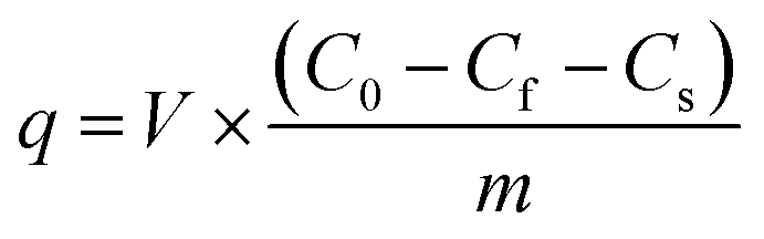
For pre-conditioning the CNT-based adsorption tubes, DI water was flowed for 10 min and pH-adjusted DI water was flowed for 5 min using the peristaltic pump. The adsorption tubes were connected to a gas-tight syringe (Hamilton, USA) using a tubing (Upchurch, USA). This assembled syringe was installed on a syringe pump (KDS 100, KD Scientific, USA).The adsorption experiments were conducted using solutions of phenolic compounds with different concentrations. These measurements were performed using both pristine and acid-treated CNTs to study the role of functional groups in the adsorption process. The flow rate through the adsorption tube was chosen by measuring the adsorption capacity for phenol at flow rates ranging from 10 μL h−1 to 1000 μL h−1 for the pristine and acid-treated CNTs. In the adsorption experiments, the target solution was flowed at 1000 μL h−1 until the solution reached the end of the CNTs, following which the flow rate was changed to a predetermined value. After changing the flow rate, 10 μL of the sample was collected. The adsorption capacity was calculated by subtracting the final concentration from initial concentration as per the following equation:
Results and discussion
Fig. 2 shows the optical microscopy images and SEM images acquired to observe the morphological changes in the CNTs. Upon mechanical densification by heat-shrinkage, the diameter of the CNT forest decreased from 1.7 mm to 1.1 mm (Fig. 2a), corresponding to a shrinkage ratio of ∼35%. The microscopic view of the VA-CNTs shows that the CNTs were highly wrinkled prior to densification, but were aligned better and exhibited significantly reduced wrinkles after densification (Fig. 2b). The pore size was estimated based on simple calculation and SEM images (Fig. S4†). Two types of pores are present in our CNT-based adsorption tube; the interstitial pores between individual CNTs and the pores between bundles of CNTs. For CNTs with diameter of 7 nm and the inter-tube distance within a bundle of 0.334 nm, we estimated based on previous studies22–24 that interstitial pores are 2.34 nm in diameter. The pores between CNT bundles have a large variation in diameter with the maximum of ∼370 nm as determined by SEM images. Brunauer, Emmett and Teller (BET) analysis (Fig. S5†) shows a local maximum at pore diameter of 2.9 nm, which corresponds to the estimated interstitial pores. The larger pores in BET measurement correspond to the ones between CNT bundles. The average pore diameter was 12.6 nm, and specific surface area was 317.1 m2 g−1.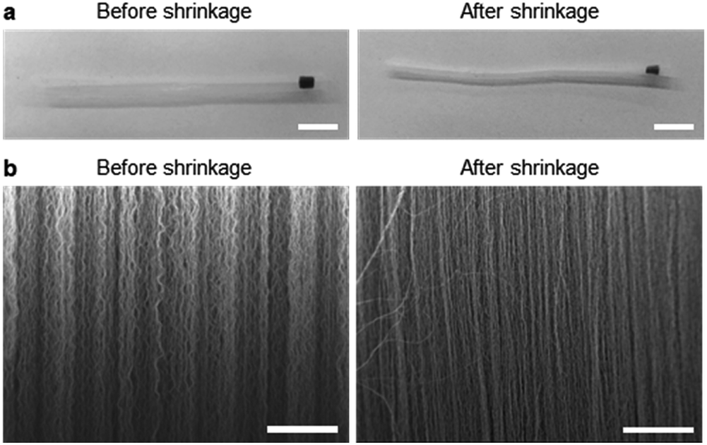 | ||
| Fig. 2 VA-CNTs packaged into a heat-shrink tubing. (a) Optical images of the VA-CNTs in a heat-shrink tubing before and after the heat treatment. Scale bar: 5 mm. (b) SEM images of the VA-CNTs in a heat-shrink tubing before and after the heat treatment. Scale bar: 5 μm. | ||
Fig. 3 shows the dependence of the adsorption capacity of the pristine and acid-treated CNTs on the flow rates of the phenol solution. For both types of CNTs, the maximum adsorption capacity for phenol (0.5 g L−1) was obtained at 10 μL h−1; 43.3 mg g−1 for the pristine and 109 mg g−1 for the acid-treated CNTs. Here, the linear velocity of the solution at 10 μL h−1 was 66 μm min−1, corresponding to a flux of 3.92 L m−2 h−1. Reducing the flow rate further would increase the adsorption capacity but would not be practical due to the extremely low flux. With the flow rate fixed at 10 μL h−1, the effect of solution pH was explored at pH values of 3, 5, 7, 9, and 11. For phenol (0.5 g L−1) and m-cresol (0.5 g L−1), both pristine and acid-treated CNTs showed an overall decrease in the adsorption capacity at pH ≥ 9, whereas the adsorption capacity of 2-chlorophenol (0.5 g L−1) decreased at pH ≥ 7 (Fig. 4a, left). Such pH dependence was more pronounced in the acid-treated CNTs than in the pristine CNTs (Fig. 4a, right). The results can be explained based on the pKa values of phenol (9.88), m-cresol (10.09), and 2-chlorophenol (8.48).25,26 The hydroxyl groups in phenolic compounds become deprotonated and negatively charged when pH > pKa. At low pH, protonation of CNTs occurs in the presence of pre-adsorbed oxygen molecules on CNTs,27 and π–π or cation–π interactions28 would dominate the adsorption, resulting in high adsorption capacity. At high pH, phenolic compounds become negatively charged. For pristine CNTs, having negligible hydroxyl or carboxyl groups as confirmed by X-ray photoelectron spectroscopy (XPS) (Fig. S3†), the negative charge would make the cation–π interaction weaker and decrease the adsorption capacity. Acid-treated CNTs become negatively charged by the deprotonation of carboxyl groups, and an electrostatic repulsion between CNTs and phenolic compounds decreases the adsorption capacity,29–34 which also explains why the adsorption capacity of acid-treated CNTs is more pH-sensitive. We also considered the effect of hydrophobic interaction in our system. According to the octanol–water partition coefficient (2-chlorophenol > m-cresol > phenol), 2-chlorophenol is the most hydrophobic among the three adsorbates, but the adsorption capacity of CNTs was the highest for m-cresol (m-cresol > phenol > 2-chlorophenol) as shown in Table S1.† The result suggests that hydrophobic interaction is not significant.
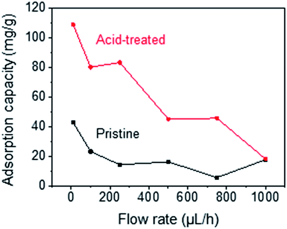 | ||
| Fig. 3 Dependence of adsorption capacity of pristine and acid-treated CNTs on flow rates of phenol solution. | ||
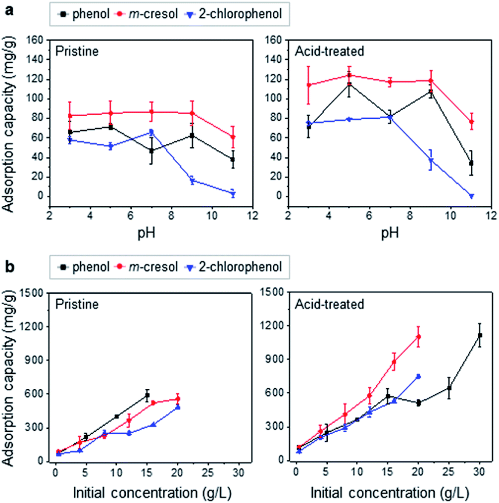 | ||
| Fig. 4 Adsorption of phenolic pollutants on CNT-based adsorption tube. (a) Adsorption capacity of pristine (left) and acid-treated (right) CNTs at different pH values. (b) Adsorption capacity of pristine (left) and acid-treated (right) CNTs at varied initial concentrations. | ||
To further confirm that the acid treatment improves the performance of adsorption tube, the adsorption capacity was measured at varied adsorbate concentrations while maintaining the pH at 5 for phenol and m-cresol and pH at 7 for 2-chlorophenol. Adsorption isotherms dictate that the adsorption capacity increase at higher adsorbate concentrations until all the adsorption sites on CNTs become occupied. Note that we estimated the adsorption capacity by comparing the amount of adsorbates before and after adsorption. Hence, when all the sites are occupied and no further adsorption occurs, the adsorption capacity cannot be estimated. Fig. 4b (left) shows the adsorption capacities of pristine VA-CNTs for the three phenolic compounds at varied initial concentrations. The values increased at higher concentrations as expected, and the maximum measurable adsorption capacities were 589 mg g−1, 558 mg g−1, and 483 mg g−1 for phenol, m-cresol, and 2-chlorophenol, respectively. For the acid-treated CNTs, the adsorption capacity was significantly higher for all the compounds, reaching 1120 mg g−1 at 30 g L−1 for phenol, 1100 mg g−1 at 20 g L−1 for m-cresol, and 748 mg g−1 at 20 g L−1 for 2-chlorophenol (Fig. 4b, right). For m-cresol and 2-chlorophenol, the adsorption capacity above 20 g L−1 could not be tested because of their limited solubility in water.
The enhancement in adsorption capacity by the acid treatment is opposite to that observed in previous studies, which reported that nitric acid treatment formed –COOH and –OH functional groups on the CNTs. Such functionalization caused a higher affinity of CNTs to water molecules than to adsorbates, thus decreasing the adsorption capacity of the CNTs.35,36 However, the acid treatment in this study was conducted under mild conditions using 20% (w/w) and 80 °C nitric acid. This mild acid treatment focuses more on the purification of CNTs rather than their heavy functionalization, as supported by previous studies.37–39 Purification removes amorphous carbons and catalysts, thereby exposing adsorption sites on CNTs and improving the adsorption capacity (Fig. S6†).
Note that both the interior and the exterior of CNTs are available for molecular adsorption, but the pressure drop is expected to be much higher across the interior than the exterior. Previous studies reported that the minimal pressure required for water to enter and exit the interior of CNTs is 120 bar and 1000 bar, respectively.40,41 In a separate measurement performed by us but not included in this work, we did not find any evidence of water flow through the interior of CNTs embedded into an epoxy matrix at 1 bar across the nanotubes. Hence, we concluded that most of the adsorption should take place on the exterior of CNTs.
The long-term stability and re-usability of the CNT-based adsorption tube need to be considered. The CNT-based adsorption tube in dry state can be stored indefinitely without any degradation of its performance. CNTs used in our study vary between freshly synthesized and 6 month-old, and we did not observe any difference in the adsorption capacity. However, once the CNTs are wetted by liquid, either for acid treatment or for adsorption experiments, nanotubes need to be stored in a solvent to prevent their drying and subsequent densification. In densified CNTs, channeling through enlarged pores between CNT bundles may dominate the flow, thereby significantly lowering the adsorption capacity. As for the re-usability, our CNT-based adsorption tube is considered disposable because of low cost and convenience of its fabrication. When necessary, however, it would be possible to regenerate CNTs by heat treatment or rinse with solvent.42–44
Finally, the adsorption capacities of the CNT-based adsorption tubes were compared with those from previous studies (Table 1).45–50 The CNT-based adsorption tubes showed outstanding adsorption capacities for phenolic compounds. As for the adsorption of phenol and m-cresol, the pristine CNTs in this study showed a comparable performance to chemically modified CNTs reported previously. When the CNTs in our adsorption tube were acid-treated, the adsorption capacity increased by 1.5 times for phenol and 2.3 times for m-cresol, compared to the best values obtained under similar conditions in previous studies. We attribute such a high adsorption capacity to the vertical alignment of CNTs and their densification by heat-shrinkage, which create a large number of adsorption sites on the inner and outer walls, groove sites, and interstitial channels between CNTs. In particular, the number of interstitial channels is drastically higher in the densified VA-CNTs than in the individual or randomly entangled CNTs in other systems.51 Studies on gas-phase adsorption reported that aligned CNTs have higher adsorption capacities than aggregated CNTs.52,53 The results are further supported by Monte Carlo simulations on the adsorption capacity of ethyl benzene, which decreased as the distance between CNTs increased.54
| Adsorbate | Adsorbent | Optimized experimental condition | Adsorption capacity (mg g−1) | Ref. | |
|---|---|---|---|---|---|
| Solution condition | Initial conc. (mg L−1) | ||||
| Phenol | HNO3 & H2SO4 purified MWNTs | pH 4.65 | 50 | 64.60 | 45 |
| HNO3 & KMnO4 MWNTs | 25 °C | 500 | 76.92 | 46 | |
| KOH etch + annealed CNTs | pH 6, 22 °C | 10–1750 | 64.10 | 47 | |
| MWNTs | 25 °C | — | 64.56 (qmax) | 48 | |
| Oxidized SWNTs | 25 °C | 10–60 | 30.86 | 30 | |
| Pristine MWNTs | pH 5 | 500 | 71.6 | This work | |
| HNO3-treated MWNTs | pH 5 | 500 | 115 | This work | |
| p-Cresol | Al2O3-coated MWNT | — | 25–200 | 54.05 | 49 |
| m-Cresol | Pristine MWNTs | PH 5 | 500 | 85.4 | This work |
| HNO3-treated MWNTs | PH 5 | 500 | 124 | This work | |
| 2-Chlorophenol | NH3-treated MWNTs | 25 °C | 50–500 | 110.3 | 50 |
| Activated CNTs | 22 ± 1 °C, pH 6 | 10–1750 | 239.8 (qmax) | 47 | |
| SWNTs | 25 ± 3 °C | 2 | 24.9 (qmax) | 34 | |
| Pristine MWNTs | PH 7 | 500 | 65.9 | This work | |
| HNO3-treated MWNTs | PH 7 | 500 | 81.2 | This work | |
Thus, we validated the performance of the CNT-based adsorption tube using phenolic compounds as model pollutants. Numerous studies reporting the excellent adsorption capability of CNTs suggest that our platform will be applicable to the removal of a wide range of organic and inorganic pollutants.19,20 Note however, that in terms of 2-chlorophenol adsorption, the performance of our adsorption tube was not impressive, but can be improved by appropriate functionalization.
Conclusions
In this study, CNT-based adsorption tubes aligned with the flow direction were fabricated by packaging VA-CNTs into a PTFE heat-shrink tubing, which removed wrinkles in the nanotubes and helped enhance their adsorption capacity for phenolic compounds. The adsorption tube, which has a tubular structure with circular cross-section, can be easily connected not only with adsorbate solutions but with chemicals for functionalization of CNTs. A mild treatment with nitric acid greatly improved the adsorption capacity of the adsorption tube, by purifying CNTs and making them more hydrophilic. Compared with previously reported CNT-based adsorbents, in the form of CNT membranes or CNTs dispersed in adsorbate solution, our platform has advantages in terms of high adsorption capacity as well as the convenience of forming a fluidic interface with other platforms. This adsorption tube prepared by the heat-shrinkage of VA-CNTs has immense potential for further optimization, and will be applicable to the removal of a wide range of organic and inorganic pollutants with high efficiency and convenience.Conflicts of interest
There are no conflicts to declare.Notes and references
- Y.-H. Shen, Water Res., 2002, 36, 1107–1114 CrossRef CAS.
- T. C. Jorgensen and L. R. Weatherley, Water Res., 2003, 37, 1723–1728 CrossRef CAS.
- T. E. Agustina, H. M. Ang and V. K. Vareek, J. Photochem. Photobiol., C, 2005, 6, 264–273 CrossRef CAS.
- L. Malaeb and G. M. Ayoub, Desalination, 2011, 267, 1–8 CrossRef CAS.
- M. Ahmaruzzaman, Adv. Colloid Interface Sci., 2008, 143, 48–67 CrossRef CAS.
- X. R. Zhao, X. Xu, X. Y. Jiang, J. Teng and J. G. Yu, Desalin. Water Treat., 2019, 148, 188–194 CrossRef.
- X. R. Zhao, X. Xu, J. Teng, N. Zhou, Z. Zhou, X. Y. Jiang, F. P. Jiao and J. G. Yu, Ecotoxicol. Environ. Saf., 2019, 176, 11–19 CrossRef CAS.
- A. Peigney, C. Laurent, E. Flahaut, R. R. Bacsa and A. Rousset, Carbon, 2001, 39, 507–514 CrossRef CAS.
- S. Joseph and N. R. Aluru, Nano Lett., 2008, 8, 452–458 CrossRef CAS.
- O. G. Apul and T. Karanfil, Water Res., 2015, 68, 34–55 CrossRef CAS.
- X. Ren, C. Chen, M. Nagatsu and X. Wang, Chem. Eng. J., 2011, 170, 395–410 CrossRef CAS.
- B. J. Hinds, N. Chopra, T. Rantell, R. Andrews, V. Gavalas and L. G. Bachas, Science, 2004, 303, 62 CrossRef CAS.
- B. Lee, Y. Baek, M. Lee, D. H. Jeong, H. H. Lee, J. Yoon and Y. H. Kim, Nat. Commun., 2015, 6, 7109 CrossRef CAS.
- B. Sarkar, S. Mandal, Y. F. Tsang, P. Kumar, K.-H. Kim and Y. S. Ok, Sci. Total Environ., 2018, 612, 561–581 CrossRef CAS PubMed.
- K. P. Lee, T. C. Arnot and D. Mattia, J. Membr. Sci., 2011, 370, 1–22 CrossRef CAS.
- H. Babich and D. L. Davis, Regul. Toxicol. Pharmacol., 1981, 1, 90–109 CrossRef CAS.
- A. Kahru, A. Maloverjan, H. Sillak and L. Põllumaa, Environ. Sci. Pollut. Res., 2002, 9, 27–33 CrossRef.
- I. P. o. C. Safety, W. H. Organization, U. N. E. Programme and I. L. Organisation, Phenol Health and Safety Guide, World Health Organization, 1994 Search PubMed.
- Ihsanullah, A. Abbas, A. M. Al-Amer, T. Laoui, M. J. Al-Marri, M. S. Nasser, M. Khraisheh and M. A. Atieh, Sep. Purif. Technol., 2016, 157, 141–161 CrossRef CAS.
- V. K. Gupta and T. A. Saleh, Environ. Sci. Pollut. Res., 2013, 20, 2828–2843 CrossRef CAS.
- K. Hata, D. N. Futaba, K. Mizuno, T. Namai, M. Yumura and S. Iijima, Science, 2004, 306, 1362–1364 CrossRef CAS.
- Y. Saito, T. Yoshikawa, S. Bandow, M. Tomita and T. Hayashi, Phys. Rev. B: Condens. Matter Mater. Phys., 1993, 48, 1907–1909 CrossRef CAS.
- F. Darkrim and D. Levesque, J. Chem. Phys., 1998, 109, 4981–4984 CrossRef CAS.
- M. S. Dresselhaus, G. Dresselhaus and R. Saito, Carbon, 1995, 33, 883–891 CrossRef CAS.
- K. Yang, L. Zhu, B. Lou and B. Chen, Chemosphere, 2005, 61, 116–128 CrossRef CAS.
- P. J. Pearce and R. J. J. Simkins, Can. J. Chem., 1968, 46, 241–248 CrossRef CAS.
- M. S. Strano, C. B. Huffman, V. C. Moore, M. J. O'Connell, E. H. Haroz, J. Hubbard, M. Miller, K. Rialon, C. Kittrell, S. Ramesh, R. H. Hauge and R. E. Smalley, J. Phys. Chem. B, 2003, 107, 6979–6985 CrossRef CAS.
- D. A. Dougherty, Science, 1996, 271, 163–168 CrossRef CAS.
- D. Lin and B. Xing, Environ. Sci. Technol., 2008, 42, 7254–7259 CrossRef CAS.
- M. de la Luz-Asunción, V. Sánchez-Mendieta, A. L. Martínez-Hernández, V. M. Castaño and C. Velasco-Santos, J. Nanomater., 2015, 2015, 14 Search PubMed.
- R. K. Singh, S. Kumar, S. Kumar and A. Kumar, J. Hazard. Mater., 2008, 155, 523–535 CrossRef CAS.
- H. Hadjar, B. Hamdi and C. O. Ania, J. Hazard. Mater., 2011, 188, 304–310 CrossRef CAS.
- M. A. Salam, M. Mokhtar, S. N. Basahel, S. A. Al-Thabaiti and A. Y. Obaid, J. Alloys Compd., 2010, 500, 87–92 CrossRef CAS.
- H. Ding, X. Li, J. Wang, X. Zhang and C. Chen, J. Environ. Sci., 2016, 43, 187–198 CrossRef.
- G. D. Sheng, D. D. Shao, X. M. Ren, X. Q. Wang, J. X. Li, Y. X. Chen and X. K. Wang, J. Hazard. Mater., 2010, 178, 505–516 CrossRef CAS PubMed.
- W. Wu, W. Chen, D. Lin and K. Yang, Environ. Sci. Technol., 2012, 46, 5446–5454 CrossRef CAS PubMed.
- P.-X. Hou, C. Liu and H.-M. Cheng, Carbon, 2008, 46, 2003–2025 CrossRef CAS.
- H. Hu, B. Zhao, M. E. Itkis and R. C. Haddon, J. Phys. Chem. B, 2003, 107, 13838–13842 CrossRef CAS.
- A. G. Rinzler, J. Liu, H. Dai, P. Nikolaev, C. B. Huffman, F. J. Rodríguez-Macías, P. J. Boul, A. H. Lu, D. Heymann, D. T. Colbert, R. S. Lee, J. E. Fischer, A. M. Rao, P. C. Eklund and R. E. Smalley, Appl. Phys. A: Mater. Sci. Process., 1998, 67, 29–37 CrossRef CAS.
- J. H. Walther, K. Ritos, E. R. Cruz-Chu, C. M. Megaridis and P. Koumoutsakos, Nano Lett., 2013, 13, 1910–1914 CrossRef CAS.
- A. Kalra, S. Garde and G. Hummer, Proc. Natl. Acad. Sci. U. S. A., 2003, 100, 10175 CrossRef CAS.
- T. Han, Y. Xiao, M. Tong, H. Huang, D. Liu, L. Wang and C. Zhong, Chem. Eng. J., 2015, 275, 134–141 CrossRef CAS.
- H. Wei, S. Deng, Q. Huang, Y. Nie, B. Wang, J. Huang and G. Yu, Water Res., 2013, 47, 4139–4147 CrossRef CAS PubMed.
- S. Li, Y. Gong, Y. Yang, C. He, L. Hu, L. Zhu, L. Sun and D. Shu, Chem. Eng. J., 2015, 260, 231–239 CrossRef CAS.
- M. H. Dehghani, M. Mostofi, M. Alimohammadi, G. McKay, K. Yetilmezsoy, A. B. Albadarin, B. Heibati, M. AlGhouti, N. M. Mubarak and J. N. Sahu, J. Ind. Eng. Chem., 2016, 35, 63–74 CrossRef CAS.
- L. Y. Jun, N. M. Mubarak, M. J. Yee, L. S. Yon, C. H. Bing, M. Khalid and E. C. Abdullah, J. Ind. Eng. Chem., 2018, 67, 175–186 CrossRef CAS.
- P. Strachowski and M. Bystrzejewski, Colloids Surf., A, 2015, 467, 113–123 CrossRef CAS.
- K. Yang, W. Wu, Q. Jing and L. Zhu, Environ. Sci. Technol., 2008, 42, 7931–7936 CrossRef CAS.
- J. Jaafari, M. G. Ghozikali, A. Azari, M. B. Delkhosh, A. B. Javid, A. A. Mohammadi, S. Agarwal, V. K. Gupta, M. Sillanpää, A. G. Tkachev and A. E. Burakov, J. Ind. Eng. Chem., 2018, 57, 396–404 CrossRef CAS.
- Q. Liao, J. Sun and L. Gao, Carbon, 2008, 46, 553–555 CrossRef CAS.
- D. J. Babu and J. J. Schneider, Chem. Ing. Tech., 2017, 89, 1273–1287 CrossRef CAS.
- D. J. Babu, M. Lange, G. Cherkashinin, A. Issanin, R. Staudt and J. J. Schneider, Carbon, 2013, 61, 616–623 CrossRef CAS.
- D. Zilli, P. R. Bonelli and A. L. Cukierman, Nanotechnology, 2006, 17, 5136–5141 CrossRef.
- S. Tasharrofi, H. Taghdisian and A. Golchoobi, J. Mol. Graphics Modell., 2018, 81, 86–96 CrossRef CAS.
Footnote |
| † Electronic supplementary information (ESI) available. See DOI: 10.1039/c9ra03948a |
| This journal is © The Royal Society of Chemistry 2019 |