
 Open Access Article
 This Open Access Article is licensed under a Creative Commons Attribution-Non Commercial 3.0 Unported Licence
Development of core–sheath structured smart nanofibers by coaxial electrospinning for thermo-regulated textiles
Liqiang Yi†
a,
Yan Wang†a,
Yini Fanga,
Ming Zhang *a,
Juming Yaoa,
Lina Wanga and
Jaromir Marekb
*a,
Juming Yaoa,
Lina Wanga and
Jaromir Marekb
aSilk Institute, College of Materials and Textiles, Zhejiang Sci-Tech University, Hangzhou 310018, China. E-mail: ylq1615642853@outlook.com; amywang1021@hotmail.com; 2016339901214@mails.zstu.edu.cn; zhangming@zstu.edu.cn; yaoj@zstu.edu.cn; lnwang@zstu.edu.cn; Tel: +86-571-86843871
bInstitute for Nanomaterials, Advanced Technologies and Innovations, Technical University of Libere, Czech Republic. E-mail: jaromir.marek@tul.cz
First published on 15th July 2019
Abstract
It is of great significance to develop phase change materials (PCMs) with high performance. The reported PCMs usually possess serious defects like low heat capacity and poor thermal stability. Here, core–sheath structured nanofibers with polyvinyl butyral (PVB) as the sheath and octadecane as the core were fabricated by melt coaxial electrospinning. Pure octadecane without any solvents was used as the core solution, thus, the optimal sample possessed very high latent heat up to 118 J g−1. We studied the influence of core feed rate and PVB solution concentration on the encapsulation rate, and the highest encapsulation rate was found when the PVB concentration was 10% and core feed rate was 0.08 mL h−1. And hexagonal cesium tungsten bronze (CsxWO3, a near infrared absorber) was introduced into the optimal sample partly to improve its conversion efficiency of solar to thermal energy, and partly absorb uncomfortable infrared light; the composite phase change material also possessed high latent heat up to 96.9 J g−1. In addition, 100 thermal cycle test proved that with a minor latent heat decrease, the prepared core–sheath structured smart nanofibers had good thermal stability, which overcomes the leakage problem of pure octadecane. Additionally, the 9 wt% CsxWO3-loaded sample had an increase in tensile strength and elongation compared with the sample without CsxWO3, indicating the good compatibility between CsxWO3 and PVB.
1. Introduction
Smart fibers are fabricated by incorporating functional materials into artificial fibers, which can respond to various external stimuli, such as mechanical forces, electricity, light, heat and so on.1–4 Various smart fibers have been reported to be used in fields such as skin care products, wound dressing products, physiological parameter monitoring, deodorant fabrics and energy storage.5–9 Particularly, energy storage fibers have attracted the attention of many researchers.Phase change material is a substance able to provide latent heat during phase transition at a constant temperature.10 As renewable energy sources, PCMs has great application prospect in solving energy crisis and environmental pollution11,12 and has been applied in solar energy storage, textile garment, food packaging, buildings, industrial waste heat recovery and other fields.13–17 PCMs include inorganic, organic compounds and mixture of organic and inorganic. Some PCMs, such as inorganic compounds, are limited by their defects like high supercooling degree, phase segregation and corrosion potential.18,19 Moreover, organic compound such as polyethylene glycol (PEG) has high water solubility,20 which limits its development. Octadecane is a good candidate of thermo-regulated material because of its high latent heat and low supercooling degree, though, like other solid–liquid PCMs, the leakage during phase change process is unavoidable, which block its application in energy storage.21,22
According to previous research, form-stable PCMs can be obtained by many approaches, such as microencapsulate, filling porous nanofibers,23 sol–gel24 and electrospinning. The size of PCMs capsule has a great influence on their melting behavior. For large-size capsule, the temperature between boundary and core part may not be the same, thus restraining the heat transfer.25 Therefore, nanofibers with small diameter can improve the thermal permeability of low-thermal conductivity PCMs. Electrospinning is a convenient and simple way to get ultrafine fibers, and the fibers have great advantages like small diameter, light weight and high specific surface area.26 Conventional electrospinning of a PCM/polymer blend solution27 may cause a removal of PCMs in the blended fiber by washing and wiping,28 but coaxial electrospinning, using in-line needles to feed different solutions, which can receive core–sheath structured nanofibers and perform good thermal stability. For example, Wan et al. chose isopropyl palmitate as core material and polyacrylonitrile as sheath material, while the latent heat was 30.8 J g−1.29 Do et al. prepared eicosane-loaded nanofibers, the latent heat was 77 J g−1.30 Wilson et al. fabricated PVOH/PCM nanofibers, and the latent heat was just 48.6 J g−1.31 Apparently, the latent heat of all the above prepared nanofibers are not very high, thus, there is great potential for development in the fabrication of core–sheath structured fibers with higher latent heat.
Lu et al. have prepared core–sheath structured nanofiber with PW as core and PAN as sheath, and CsxWO3 was loaded into the fiber,32 but they just studied the influence of core feed rate on the morphology, and kerosene solution of PW was used as the core solution, so the latent heat of the final composite phase change material was only 60.31 J g−1. In this study, the core–sheath structured nanofibers was fabricated by melt coaxial electrospinning, and we studied the influence of core feed rate and PVB solution concentration on the encapsulation rate. Pure liquid octadecane was used as core solution, so the final latent heat of the composite phase change material can be as high as 96.9 J g−1. As we all know, near-infrared light accounts for more than half of solar energy, to improve the efficiency of converting solar energy to thermal energy, CsxWO3 was successfully incorporated into it. In addition, 100-thermal cycle test on the optimized sample was performed and the conclusion demonstrated the prepared core–sheath structured smart nanofibers had good thermal stability. Additionally, the 9 wt% CsxWO3-loaded sample has an increase in tensile strength and elongation compared with the sample without CsxWO3. This study has certain reference for the synthesis of comfortable thermo-regulated textiles.
2. Experimental
2.1. Materials
Polyvinyl butyral (PVB, B-98, Mw = 40![[thin space (1/6-em)]](https://www.rsc.org/images/entities/char_2009.gif) 000–70000) and petroleum ether were purchased form Aladdin Chemistry Co., Ltd. Octadecane (99%, melting point is about 28.2 °C) was purchased from Macklin Biochemical Technology Co., Ltd. Ethanol was purchased form Hangzhou Gaojing Fine Chemical Industry Co., Ltd. CsxWO3 was supplied by Shanghai Buwei Applied Material Technology Co., Ltd.
000–70000) and petroleum ether were purchased form Aladdin Chemistry Co., Ltd. Octadecane (99%, melting point is about 28.2 °C) was purchased from Macklin Biochemical Technology Co., Ltd. Ethanol was purchased form Hangzhou Gaojing Fine Chemical Industry Co., Ltd. CsxWO3 was supplied by Shanghai Buwei Applied Material Technology Co., Ltd.
2.2. Fabrication of the core–sheath structured smart nanofibers
To obtain the sheath solution, PVB with different concentrations of 10, 12 and 14 wt% was added into ethanol with magnetic stirring for 24 h. CsxWO3 was added into 10% PVB solution with concentration 3, 6 and 9 wt%, followed by ultrasonic for 2 h and magnetic stirring for 24 h. The concentric stainless-steel needles were consisted of an outer needle and an inner needle. For the outer needle, outer/inner diameters were 1.49/1.01 mm and for the inner needle, outer/inner diameters were 0.72/0.41 mm. The sheath feed rate was 0.5 mL h−1, and the core feed rate was adjusted as 0.06, 0.08, 0.1, 0.12 mL h−1 respectively. The applied voltage was 16.3–18.9 kV and the distance from tip to collector was about 11 cm. To melt octadecane, the ambient temperature was controlled at 50 °C. Finally, the prepared samples were dried at room temperature for 24 h to remove the remaining solvent.2.3. Thermal cycle test
100-thermal cycle test in a thermostatic oven between 25 and 50 °C was performed to investigate the thermal stability of the smart fibers. The films were first heated to 50 °C to melt octadecane, and then cooled down to room temperature.2.4. Characterization methods
The morphologies of the prepared nanofibers were observed by field emission scanning electron microscope (FE-SEM, ULTRA55, Zeiss), and the acceleration voltage was 3 kV. Before observation, all the samples were pre-soaked in petroleum ether for 24 h and then coated with a thin layer of gold. To obtain cross-sectional FE-SEM image of PVB@Octa (PVB@Octa means core–sheath structured, with PVB sheath and octadecane core fibers), the samples were soaked in liquid nitrogen for a while to make it brittle, then cut with a sharp knife, and soaked in petroleum ether for 24 h and then coated with a thin layer of gold. The diameters of 30 random fibers were measured by ImageJ software, and their mean values were calculated. Transmission electron microscope (TEM, JEM-2100, JOEL) was used to investigate the core–sheath structure of the prepared nanofibers and the acceleration voltage was 200 kV. The TEM samples were prepared by depositing nanofibers onto 400-mesh carbon-coated Cu grids and then soaking in petroleum ether for 24 h. Differential scanning calorimetry (DSC, Q2000) was implemented in nitrogen flow, the samples were heated from 0 to 50 °C and then cooled from 50 to 0 °C, the heating and cooling rate were 10 K min−1. UV/VIS/NIR spectrophotometer (UH4150) was used to study the light transmittance of the samples. PVB, PVB@Octa, PVB@Octa@Cs9% (PVB means pure electrospinning PVB film, PVB@Octa@Cs9% means CsxWO3-loaded PVB@Octa, all PVB concentration was 10%) were photographed by infrared imager after 20 s irradiation by an IR lamp to directly see the absorption of near-infrared light by the samples. (The samples were put on a glass slide and the distance from samples to bulb was about 10 cm and the samples were cut into about 0.5 cm × 0.5 cm × 0.04 cm pieces.) Tensile property was measured by multifunctional mechanical tester (KES-G1) with extension rate of 0.1 cm s−1 at 25 °C. The samples were cut into 0.5 × 2 cm pieces, the thickness of the membrane was measured separately and accurate to 1 μm. Each sample was tested in triplicate.3. Results and discussion
Briefly, the core–sheath structured smart fibers were fabricated via coaxial electrospinning technique, as shown in Fig. 1, sheath solution and core solution were poured into two individual 10 mL plastic syringe connected to two in-line stainless-steel needles. The sheath solution was connected with the outer needle, and the core solution was connected with the inner needle. When a high voltage was applied, the tension generated by the charges that accumulated on the surface of the polymer solution caused the polymer solution to form a jet with the core solution. During the jet process, the solvent vaporized and the fibers could be obtained on the roller collector. | ||
| Fig. 1 Schematic illustration of the coaxial electrospinning technique. | ||
Fig. 2 shows the mean diameter of fibers with different PVB solution concentration and core feed rate. It clearly shows that the diameter of the fibers gradually increases with the increase of PVB solution concentration, this is because that the viscosity of PVB solution increases with the increase of PVB solution concentration, and high viscosity results in big diameter. When the concentration is constant, the increase of core feed rate has no great influence on the diameter.
 | ||
| Fig. 2 Three dimensional histogram of mean fiber diameter at different PVB concentration and core feed rate. | ||
As shown in Fig. 3, PVB solution concentration and core feed rate have a great influence on the morphology of the fibers. The fibers show a cylindrical and bead-free morphology with PVB concentration of 10% and core feed rate of 0.08 mL h−1. While when the core feed rate increases to 0.1 and 0.12 mL h−1, the fibers become uneven, and spindle-like beads appear. Similarly, at concentration of 12 and 14%, the fibers are cylindrical and bead-free when the core feed rates are 0.08 and 0.1 mL h−1, but when the core feed rate increases to 0.12 mL h−1, spindle-like structure appears. This may be due to the fact that as the core feed rate increases, there is too much core material inside the fibers, and the viscosity of the polymer solution is not high enough, resulting in this uneven structure, and part of the octadecane has not been incorporated, which can be proven by DSC analyses. The solution to this problem is to increase the concentration of the polymer solution, as shown in Fig. 3d–f. When the core feed rate is 0.1 mL h−1 and the concentration is 10%, the fibers have spindle-like beads, as the concentration increases to 12 and 14%, the fibers become rod-shaped. This is because the viscosity of the solution increases with the increase of PVB solution concentration, which makes it easier for the sheath to remain uniform when the core layer is stretched. The increase of the concentration will also increase the diameter of the fibers, which to some extent also makes the spindle-like structure not easy to appear.
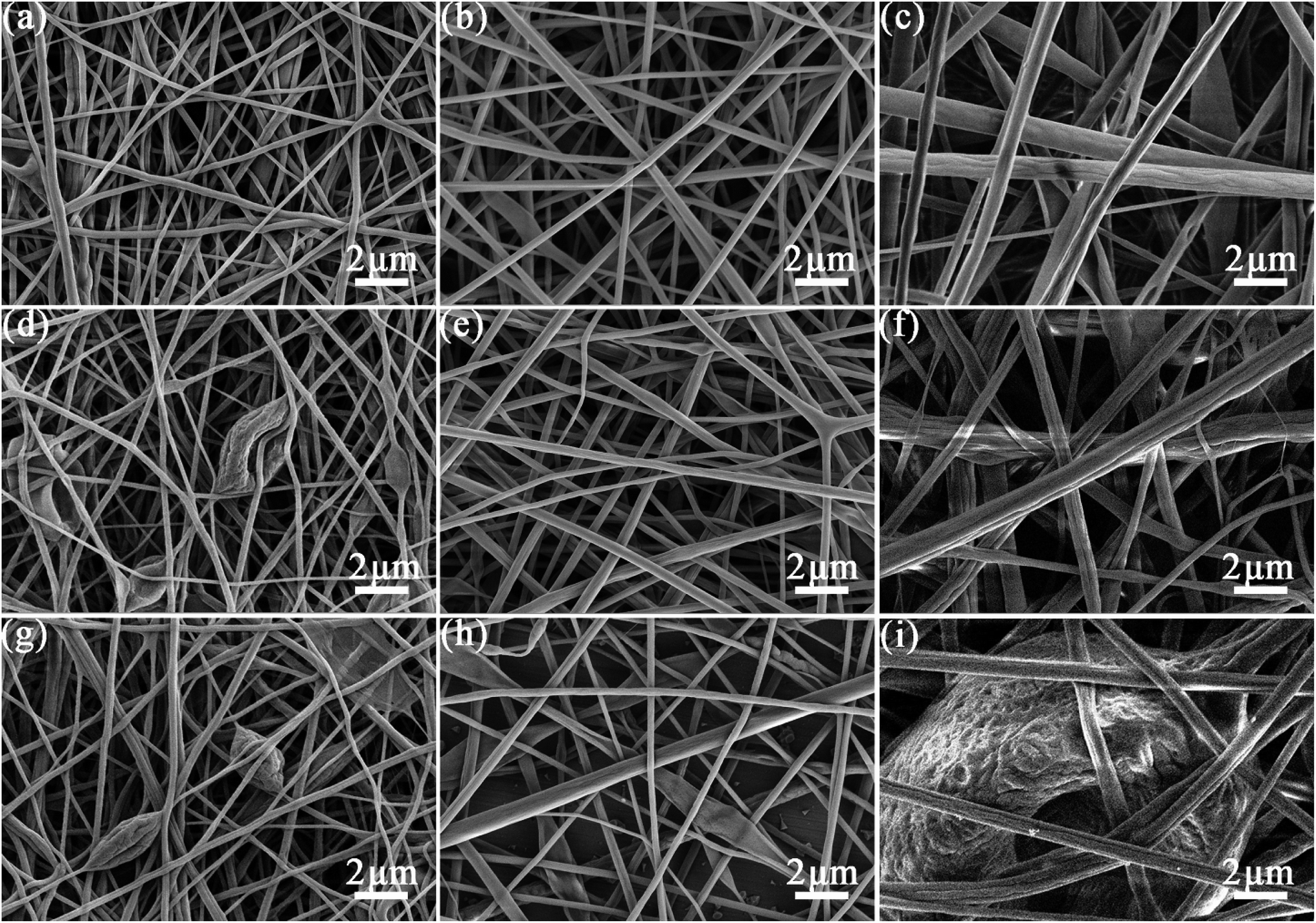 | ||
| Fig. 3 FE-SEM images of the electrospun core–sheath structured nanofibers with different core feed rates: (a–c) 0.08 mL h−1; (d–f) 0.1 mL h−1; (g–i) 0.12 mL h−1; samples with different PVB concentration (wt%): (a, d and g) 10%; (b, e and h) 12%; (c, f and i) 14%. | ||
Table 1 is the DSC analyses data of samples with different PVB solution concentration and core feed rate and Fig. 4 is the DSC curves of all PVB@Octa samples, pure PVB and pure octadecane. We can get the conclusion that at a certain concentration, the latent heat increases with the increase of core feed rate, and finally it will reach a plateau, which may be the highest encapsulation rate under this experimental condition. For example, at concentration of 12%, the latent heat increases a lot when core feed rate goes up from 0.06 mL h−1 to 0.1 mL h−1, while when the core feed rate rises from 0.1 mL h−1 to 0.12 mL h−1, the latent heat increases only a little, similar situation happens when PVB concentrations are 10% and 14%, with the increase of core feed rate, the latent heat of the fibers at various concentrations will reach to around 130 J g−1 and be stable, but the morphologies of the fibers those at the highest latent heat are spindle-like. At a certain core feed rate, the latent heat generally decreases with the increase of the PVB solution concentration. This is because that with the increase of PVB solution concentration, the component of PVB in the core–sheath structured fibers rises, while PVB only contributes to the increase in weight and no phase transition occurs. Therefore, the latent heat of the entire fibers decreases. Finally, we can get the optimized sample: PVB solution concentration is 10% and core feed rate is 0.08 mL h−1. The latent heat is up to 118 J g−1, and the morphology of the fibers are cylindrical and bead-free. For pure PVB, there was no phase transition according to Fig. 4d, and the latent heat of pure octadecane was about 242.2 J g−1.
| Concentration (wt%) | Feed rate (mL h−1) | Tonset (°C) | ΔHm (J g−1) | Tonset (°C) | ΔHc (J g−1) |
|---|---|---|---|---|---|
| 10 | 0.06 | 26.36 | 94.89 | 25.92 | 95.77 |
| 0.08 | 26.89 | 118 | 25.67 | 120.1 | |
| 0.1 | 25.76 | 128.6 | 25.11 | 135.1 | |
| 0.12 | 28.04 | 128.7 | 24.77 | 127.4 | |
| 12 | 0.06 | 26.61 | 50.24 | 25.83 | 50.85 |
| 0.08 | 27.01 | 100.7 | 26.09 | 103.5 | |
| 0.1 | 26.31 | 126.7 | 25.39 | 132 | |
| 0.12 | 26.51 | 133.6 | 25.72 | 139.3 | |
| 14 | 0.06 | 26.45 | 51.2 | 25.61 | 35.64 |
| 0.08 | 26.66 | 82.02 | 26.03 | 69.36 | |
| 0.1 | 26.84 | 114.8 | 25.89 | 114.7 | |
| 0.12 | 26.95 | 126.9 | 26.24 | 128.3 |
 | ||
| Fig. 4 DSC curves of samples with different PVB concentration: (a) 10%; (b) 12%; (c) 14% and (d) pure PVB and octadecane. | ||
Fig. 5 is the SEM image of PVB@Octa@Cs with different mass fraction of CsxWO3. The addition of CsxWO3 has no great influence on the morphology of fibers, the surface is smooth, and there are only a few bulges. As shown in Table 2, the Tonset points are almost the same before and after loading CsxWO3, and different concentrations of CsxWO3 have no effect on Tonset point. While the latent heat of the fibers after adding CsxWO3 has a decline which is caused by the density difference of CsxWO3 and PVB, the density of CsxWO3 is higher than PVB. So with a similar diameter, higher weight of PVB@Octa@Cs results in a lower latent heat in its calculation. And the fibers with 9% CsxWO3 still possess a very high latent heat up to 96.9 J g−1.
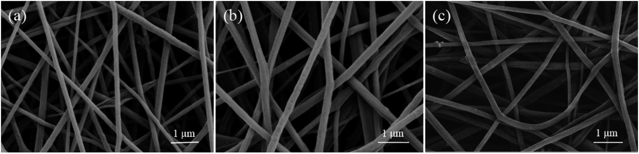 | ||
| Fig. 5 FE-SEM image of PVB@Octa@Cs3%; PVB@Octa@Cs6% and PVB@Octa@Cs9%. | ||
| Samples | Tonset (°C) | ΔHm (J g−1) | Tonset (°C) | ΔHc (J g−1) |
|---|---|---|---|---|
| PVB@Octa@Cs3% | 26.65 | 104.8 | 25.76 | 102.9 |
| PVB@Octa@Cs6% | 26.57 | 101.9 | 25.55 | 100.6 |
| PVB@Octa@Cs9% | 26.63 | 96.9 | 25.44 | 98.61 |
Fig. 6 shows the DSC curves of PVB@Octa@Cs9% before and after 100 thermal cycles. The areas of two peaks are almost the same, and the latent heat after thermal cycle test is 95.73 J g−1, which is very close to 96.9 J g−1, so we can get the conclusion that the core–sheath structured smart nanofibers have good thermal stability.
 | ||
| Fig. 6 DSC curves of PVB@Octa@Cs9% before and after 100 cycles. | ||
Fig. 7a and b clearly show the core–sheath structure of the fibers, indicating that octadecane is successfully encapsulated into PVB. Fig. 7c and d are the TEM images of smart fibers. The black dots in the image indicate that cesium tungsten bronze is successfully incorporated into the fibers.
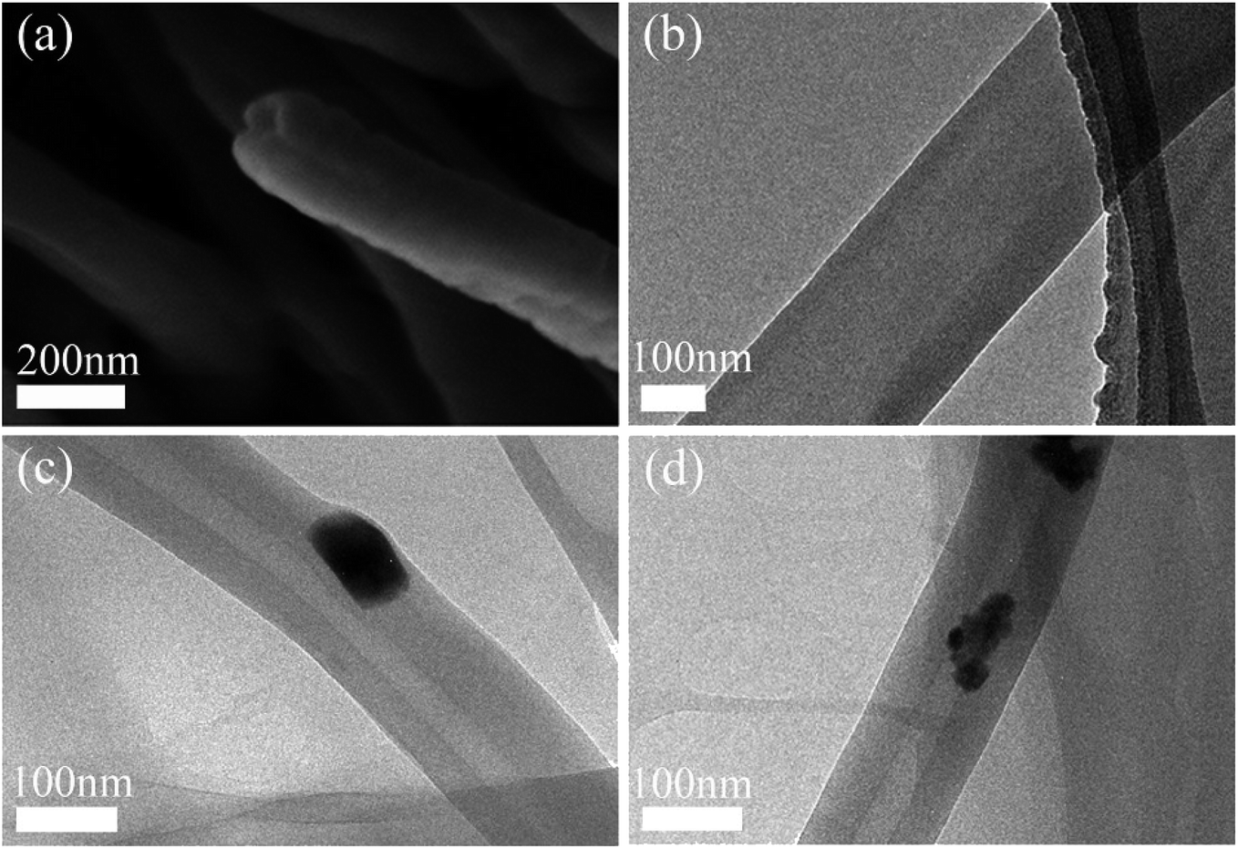 | ||
| Fig. 7 (a) Cross-sectional SEM image of PVB@Octa; (b) TEM image of PVB@Octa; (c and d) TEM image of PVB@Octa@Cs. | ||
As shown in Fig. 8a, the EDS elemental analysis shows Cs and W, which belongs to CsxWO3. Fig. 8b is the UV-VIS-NIR transmission diagram of smart fibers with different CsxWO3 concentration and PVB@Octa. Cs3%, Cs6%, Cs9% represents the concentration of CsxWO3 is 3, 6, 9 wt%, respectively. Visible light has a wavelength range of 380–780 nm, and the peaks of the CsxWO3-loaded samples in the figure correspond to this value, indicating that cesium tungsten bronze does not absorb much visible light, while for PVB@Octa sample, there is no peak at this range, and the sample has highest transmissivity compared with the CsxWO3-loaded samples. It can also be seen from the figure that with the increase of the concentration of CsxWO3, the transmissivity gradually decreases, as the transmissivity even goes as low as about 5% when CsxWO3 concentration is 9%, which means that the smart fiber has good performance of NIR absorption. Hence, the addition of CsxWO3 is helpful to improve the heat storage performance of the smart fiber.
 | ||
| Fig. 8 (a) EDS curve of PVB@Octa@Cs; (b) UV-VIS-NIR spectroscopy of PVB@Octa and PVB@Octa@Cs with different CsxWO3 concentration. | ||
In order to directly observe the infrared light absorption performance of the smart fibers, the infrared lamp is used to irradiate the fibers, and the thermographic images are made. Fig. 9 is the thermographic images of PVB (left), PVB@Octa (middle), and PVB@Octa@Cs (right), (a), (b), (c) and (d) are the images with different duration time of 1, 5, 13, and 18 s after 20 s irradiation respectively. Fig. 8a shows that one second later after 20 s irradiation, the temperature of PVB@Octa@Cs is 39.3 °C, while the temperature of PVB@Octa and PVB are only 31.1 °C and 29 °C, which are almost the same as the ambient temperature. The temperature difference between PVB@Octa@Cs and PVB can be as high as 10 °C. Fig. 9b–d show that after 5, 13 and 18 s, the temperature of the three samples all decreases, and PVB@Octa@Cs shows the highest temperature which is always higher than the ambient temperature. Therefore, the results show that the addition of CsxWO3 can improve the efficiency of converting solar energy to thermal energy.
 | ||
| Fig. 9 Thermographic images of PVB; PVB@Octa; PVB@Octa@Cs with different durable time of (a) 1 s; (b) 5 s; (c) 13 s and (d) 18 s after 20 s irradiation by an IR lamp. | ||
Fig. 10 is the stress–strain curves of PVB@Octa and PVB@Octa@Cs. Generally, all samples have a low elongation because of the load of brittle octadecane. With the increase of mass fraction of CsxWO3, the tensile strength of PVB@Octa@Cs gradually increases. PVB@Octa has a higher tensile strength compared to PVB@Octa@Cs3% and PVB@Octa@Cs6%, but PVB@Octa@Cs9% has a highest tensile strength and elongation which even higher than PVB@Octa, indicating that there is good compatibility between PVB and CsxWO3.
 | ||
| Fig. 10 Stress–strain curves of PVB@Octa and PVB@Octa@Cs. | ||
4. Conclusions
In summary, core–sheath structured nanofibers with polyvinyl butyral (PVB) as sheath and octadecane as core was fabricated by melt coaxial electrospinning successfully. Hexagonal cesium tungsten bronze was loaded into the nanofibers to improve its converting efficiency of solar to thermal energy. The DSC results show the prepared smart fibers have an extremely high latent heat up to 96.9 J g−1. And 100 thermal cycle test shows a good thermal stability of the smart fibers, which overcome the leakage problem. Additionally, the 9 wt% CsxWO3-loaded sample has an increase in mechanical properties. Hence, this work provides a strong support for the application of smart fibers in the field of thermo-regulated textiles.Conflicts of interest
There are no conflicts to declare.Acknowledgements
The authors acknowledge financial support from Key Program for International Cooperation Projects of China (2016YFE0131400).References
- M. Stoppa and A. Chiolerio, Sensors, 2014, 14, 11957–11992 CrossRef CAS.
- J. Hu, H. Meng, G. Li and S. I. Ibekwe, Smart Mater. Struct., 2012, 21, 053001 CrossRef.
- B. Pause, J. Ind. Text., 2016, 33, 93–99 CrossRef.
- H. Y. Jiang, S. Kelch and A. Lendlein, Adv. Mater., 2006, 18, 1471–1475 CrossRef CAS.
- J. Hu, W. Liu and B. Liu, US Pat., US007780979B2, 2010.
- H. Tamura, Y. Tsuruta and S. Tokura, Mater. Sci. Eng. C, 2002, 20, 143–147 CrossRef.
- S. Pasche, S. Angeloni, R. Ischer, M. Liley, J. Luprano and G. Voirin, Adv. Sci. Technol., 2008, 57, 80–87 CAS.
- J. Hu, F. Zeng and P. Li, US Pat., US007968083B2, 2011.
- K. Jost, G. Dion and Y. Gogotsi, J. Mater. Chem. A, 2014, 2, 10776 RSC.
- B. Rezaei, M. Ghani, M. Askari, A. M. Shoushtari and R. M. A. Malek, Adv. Polym. Technol., 2016, 35, 21534 CrossRef.
- S. K. Song, T. T. Zhao, F. Qiu, W. T. Zhu, T. R. Chen, Y. Guo, Y. Zhang, Y. Q. Wang, R. Feng, Y. Liu, C. X. Xiong, J. Zhou and L. J. Dong, Energy, 2019, 172, 1144–1150 CrossRef CAS.
- S. K. Song, T. T. Zhao, W. T. Zhu, F. Qiu, Y. Q. Wang and L. J. Dong, ACS Appl. Mater. Interfaces, 2019, 11, 20828–20837 CrossRef CAS.
- M. Kenisarin and K. Mahkamov, Renewable Sustainable Energy Rev., 2007, 11, 1913–1965 CrossRef CAS.
- G. Li, G. Hong, D. Dong, W. Song and X. Zhang, Adv. Mater., 2018, 30, 1801754 CrossRef.
- W. Chalco-Sandoval, M. J. Fabra, A. López-Rubio and J. M. Lagaron, Eur. Polym. J., 2015, 72, 23–33 CrossRef CAS.
- A. K. Pandey, M. S. Hossain, V. V. Tyagi, N. Abd Rahim, J. A. L. Selvaraj and A. Sari, Renewable Sustainable Energy Rev., 2018, 82, 281–323 CrossRef.
- S. K. Song, F. Qiu, W. T. Zhu, Y. Guo, Y. Zhang, Y. Y. Ju, R. Feng, Y. Liu, Z. Chen, J. Zhou, C. X. Xiong and L. J. Dong, Sol. Energy Mater. Sol. Cells, 2019, 193, 237–245 CrossRef CAS.
- B. Zalba, J. M. Marín, L. F. Cabeza and H. Mehling, Appl. Therm. Eng., 2003, 23, 251–283 CrossRef CAS.
- S. A. Mohamed, F. A. Al-Sulaiman, N. I. Ibrahim, M. H. Zahir, A. Al-Ahmed, R. Saidur, B. S. Yılbaş and A. Z. Sahin, Renewable Sustainable Energy Rev., 2017, 70, 1072–1089 CrossRef CAS.
- C. Chen, L. Wang and Y. Huang, Polymer, 2007, 48, 5202–5207 CrossRef CAS.
- M. F. Demirbas, Energy Sources, Part B, 2006, 1, 85–95 CrossRef CAS.
- Y. Lu, X. Xiao, Y. Zhan, C. Huan, S. Qi, H. Cheng and G. Xu, ACS Appl. Mater. Interfaces, 2018, 10, 12759–12767 CrossRef CAS.
- H. Ke and Q. Wei, Thermochim. Acta, 2019, 671, 10–16 CrossRef CAS.
- A. Babapoor, G. Karimi, S. I. Golestaneh and M. A. Mezjin, Appl. Therm. Eng., 2017, 118, 398–407 CrossRef CAS.
- L. F. Cabeza, C. Castellón, M. Nogués, M. Medrano, R. Leppers and O. Zubillaga, Energy Build., 2007, 39, 113–119 CrossRef.
- N. Zhang, Y. Yuan, X. Cao, Y. Du, Z. Zhang and Y. Gui, Adv. Eng. Mater., 2018, 20, 1700753 CrossRef.
- C. Chen, L. Wang and Y. Huang, Appl. Energy, 2011, 88, 3133–3139 CrossRef CAS.
- C. Cherif, N. H. A. Tran, M. Kirsten, H. Bruenig and R. Vogel, eXPRESS Polym. Lett., 2018, 12, 203–214 CrossRef CAS.
- Y. Wan, P. Zhou, Y. Liu and H. Chen, RSC Adv., 2016, 6, 21204 RSC.
- C. V. Do, T. T. T. Nguyen and J. S. Park, Korean J. Chem. Eng., 2013, 30, 1403–1409 CrossRef CAS.
- W. Chalco-Sandoval, M. J. Fabra, A. López-Rubio and J. M. Lagaron, J. Appl. Polym. Sci., 2016, 133, 43903 CrossRef.
- Y. Lu, X. D. Xiao, J. Fu, C. M. Huan, S. Qi, Y. J. Zhan, Y. Q. Zhu and G. Xu, Chem. Eng. J., 2019, 355, 532–539 CrossRef CAS.
Footnote |
| † Liqiang Yi and Yan Wang contributed equally. |
| This journal is © The Royal Society of Chemistry 2019 |