DOI:
10.1039/C9RA03611C
(Paper)
RSC Adv., 2019,
9, 26949-26955
The grain growth mechanism of nano-CaO regenerated by nano-CaCO3 in calcium looping
Received
14th May 2019
, Accepted 6th August 2019
First published on 28th August 2019
Abstract
The grain growth mechanism of nano-CaO-based CO2 adsorbents in calcium looping (CaL) process was studied to figure out the main factors affecting sorption durability. First, the thermal growth characteristics of nano-CaCO3 grains and nano-CaO grains at 750–850 °C was measured to fit the grain growth kinetic models. The activation energy data of grain growth of nano-CaCO3 and nano-CaO were obtained as 104.8 kJ mol−1 and 212.8 kJ mol−1 respectively, which indicated that the grain growth of nano-CaCO3 was easier than that of nano-CaO. Then, the grain sizes of regenerated nano-CaO undergoing 10 CaL cycles were compared with those derived from nano-CaCO3 suffering high temperature heat-treatment under the same looping temperature and time. It was found that CaCO3–CaO chemical conversion could accelerate the grain growth of regenerated nano-CaO. Based on these results, the grain growth mechanism of regenerated nano-CaO grain in CaL process was proposed. The thermal growth of nano-CaCO3 grain was the key issue to influence the grain growth of regenerated nano-CaO. Therefore, shortening the high temperature residence time as well as preventing the interface contact of nano-CaCO3 grains were good for limiting the grain growth of regenerated nano-CaO.
1. Introduction
Using the reversible reaction of CaO-based adsorbents (as shown in eqn (1)) to capture greenhouse gas CO2![[thin space (1/6-em)]](https://www.rsc.org/images/entities/char_2009.gif) 1 at high temperature, termed CaL technology,2,3 is widely used in many fields such as zero-emission power generation technologies,4,5 reactive sorption-enhanced reforming for hydrogen production (ReSER)6–8 and energy storage systems in chemical heat pumps.9,10 One of the bottleneck problems of CaL is that the sorption capacity of CaO-based adsorbents will always rapidly decay after several cycles, which is referred to as the “deactivation phenomenon”.11 It seriously affects the reversibility and economic feasibility of the CaL technology,12 so it is significant to study the deactivation mechanism of CaO-based adsorbents.
1 at high temperature, termed CaL technology,2,3 is widely used in many fields such as zero-emission power generation technologies,4,5 reactive sorption-enhanced reforming for hydrogen production (ReSER)6–8 and energy storage systems in chemical heat pumps.9,10 One of the bottleneck problems of CaL is that the sorption capacity of CaO-based adsorbents will always rapidly decay after several cycles, which is referred to as the “deactivation phenomenon”.11 It seriously affects the reversibility and economic feasibility of the CaL technology,12 so it is significant to study the deactivation mechanism of CaO-based adsorbents.| | |
CaO + CO2 ⇌ CaCO3, ΔH298 = −178.8 kJ mol−1
| (1) |
The phenomenon of the growth of nano-CaO grain sizes can be often observed in CaL process, which means the sintering of CaO. Feng et al.13 found that the regenerated nano-CaO grain sizes in nano-CaO-based adsorbents increased from 37 nm to 62 nm after 6 CaL cycles. According to the research of Sun et al.,14 the reason for deactivation of adsorbents was the sintering of CaO. It showed that the growth of nano-CaO grains led to the loss of specific surface area, which meant the reduction of the numbers of active CaO sites for adsorbing CO2. Therefore, it is crucial to understand the grain growth mechanism of nano-CaO during CaL process. The growth of nano-CaO grains mainly occurrs in the high temperature regeneration stage and the growth degree is controlled by regeneration temperature and time. Dash et al.15 found that the grain size of CaO would increase from 17 nm to 47 nm when the regeneration temperature was raised from 1000 °C to 1200 °C. Zhu et al.16 found that the CaO grain size would grow from 51.5 nm to 75.1 nm when the regeneration time was prolonged from 1 h to 4 h at 800 °C.
The grain size of regenerated nano-CaO is actually determined by the interaction of several structural changes including the thermal growth of CaO grains. The regeneration process of adsorbents can be roughly divided into three substeps: (1) thermal growth of nano-CaCO3 grains, (2) CaCO3 convert to CaO and (3) thermal growth of CaO grains. In recent researches, rapid growth of nano-CaCO3 grain has been regarded as the fundamental reason for the growth of regenerated nano-CaO grains. Because the Tammann temperature of CaCO3 (533 °C) is significantly lower than that of CaO (1154 °C).17 Müller et al.18 found that increasing the heating rate between sorption and regeneration steps to reduce the residence time of nano-CaCO3 in the high temperature could slow down the deactivation trend of adsorbents. Nevertheless, the research on the grain growth mechanism of nano-CaO in CaL process is still incomplete. It is difficult to figure out which regeneration substep is the key issue to influence the grain growth of nano-CaO because of the coupling. Therefore, it is necessary to quantify and compare the impact of three regeneration substep on the grain growth of nano-CaO by designing decoupling experiments at the same regeneration conditions.
In this paper, the grain growth kinetic model of nano-CaCO3 was fitted under the heat-treatment conditions (temperature 750–850 °C, time 0–240 min) with the protective atmosphere of CO2. Also, the grain growth kinetic model of nano-CaO would be got at the same conditions with N2 protection. The dominant one for the increase of regenerated nano-CaO grain sizes could be found by comparing their activation energy for grain growth. Moreover, the grain sizes, pore structure and sorption performance of regenerated nano-CaO were compared separately through the CaL process and the heat-treatment looping (HtL) process without any reactions to investigate the effect of CaCO3–CaO conversion on the grain growth of regenerated nano-CaO. Finally, the grain growth mechanism of regenerated nano-CaO in CaL process was proposed.
2. Experimental
2.1 Heat-treatment of nano-CaCO3 and nano-CaO samples
Commercial nano-CaCO3 (>95% purity, Huzhou Ling Hua Ltd. China) and nano-CaO derived from commercial nano-CaCO3 decomposition were adopted. The schematic diagram of a laboratory-scale fixed bed reactor was shown as Fig. 1. The diameter of the stainless tube in the reactor was Φ12 × 1 mm and the length was 400 mm. The temperature stable section was filled by 2 g nano-CaCO3 (or nano-CaO). The temperature was adjusted by a temperature controller. The feed flow rates of CO2 and N2 were regulated by the mass flow meters. First, the fixed bed was heated to a set heat-treatment temperature (750–850 °C) at a heating rate of 15 °C min−1, then held for a set period of time (60–240 min). When the nano-CaCO3 was heated, the reactor was filled with CO2 atmosphere to keep CaCO3 state. On the contrary, when the nano-CaO was heated, the reactor was filled with N2 atmosphere to keep CaO state. The heat-treatment conditions and the corresponding samples' name were shown in Table 1. CaC-α/β and CaO-α/β (α = 0, 750, 800 and 850; β = 0, 60, 120, 240) referred to the nano-CaCO3 and nano-CaO sample under heat-treatment temperature of α °C and heat-treatment time of β min, respectively. CaC-0/0 and CaO-0/0 referred to fresh nano-CaCO3 and fresh nano-CaO without heat-treatment.
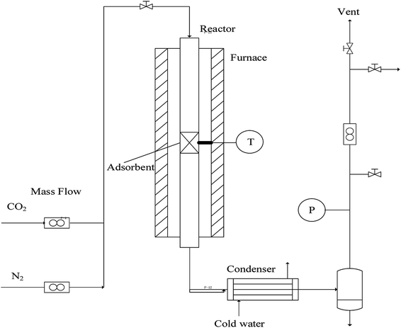 |
| | Fig. 1 Diagram of the fixed bed reactor system. | |
Table 1 Heat-treatment conditions of nano-CaCO3 and nano-CaO samples
| Sample name |
Heat-treatment temperature (°C) |
Heat-treatment time (min) |
| CaCO3 |
CaO |
| CaC-0/0 |
CaO-0/0 |
— |
— |
| CaC-750/60 |
CaO-750/60 |
750 |
60 |
| CaC-750/120 |
CaO-750/120 |
750 |
120 |
| CaC-750/240 |
CaO-750/240 |
750 |
240 |
| CaC-800/60 |
CaO-800/60 |
800 |
60 |
| CaC-800/120 |
CaO-800/120 |
800 |
120 |
| CaC-800/240 |
CaO-800/240 |
800 |
240 |
| CaC-850/60 |
CaO-850/60 |
850 |
60 |
| CaC-850/120 |
CaO-850/120 |
850 |
120 |
| CaC-850/240 |
CaO-850/240 |
850 |
240 |
2.2 CaL and HtL processes of nano-CaCO3
2 g commercial nano-CaCO3 was filled in the temperature stable section of the fixed bed reactor. The CaL process was operated at atmospheric pressure. First, heating the reactor to 800 °C and holding for 50 min in N2 gas flow (100 mL min−1) to complete decomposition of CaCO3. Then cooling the reactor to 600 °C and maintaining for 25 min with CO2–N2 (20 mL min−1 CO2, 80 mL min−1 N2) atmosphere to complete carbonation of CaO. The regeneration–carbonation cycle was repeated to 10 times and the adsorbent samples were collected after carbonation period at different cycles. In contrast to the above CaL process, HtL process indicated that nano-CaCO3 was thermally cycled between 600 °C (25 min) and 800 °C (50 min) under the CO2 atmosphere protection without any reactions. HtL-N and CaL-N represented samples after the Nth HtL cycle and the Nth CaL cycle, respectively (N = 1, 5, 10).
2.3 Characterization
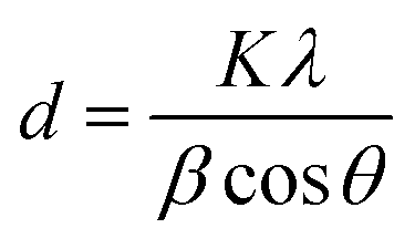
In this paper, the X-ray diffraction pattern of adsorbents was tested by XRD (D/MAX-RA, Rigaku, Japan). The characteristic peaks of 2θ = 29.5°, 36.2° and 39.5°; 2θ = 53.9°, 64.2° and 67.4° were used to calculate the average grain size of nano-CaCO3 and nano-CaO, respectively.16 It could be determined by the Scherrer equation, as follows:| |
 | (2) |
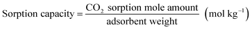
The sorption performance of the adsorbent was measured using TGA (Pyris1, PerkinElmer, USA). The operation conditions of carbonation stage and regeneration stage were 600 °C–20%CO2/80%N2–20 min and 750 °C–100%N2–10 min, respectively. The sorption capacity and sorption rate were calculated according to eqn (3) and (4):
| |
 | (3) |
| |
 | (4) |
In addition, the specific surface area (Brunauer–Emmer–Teller, BET) and desorption average pore diameter (Barrett–Joyner–Halenda, BJH) analyses were conducted by nitrogen physisorption at −196 °C by means of a Micrometrics ASAP2020 apparatus. The morphology of the adsorbent was investigated by scanning electron microscopy (SEM, S-4800, Hitachi, Japan).
3. Results and discussion
3.1 The grain growth characteristics of nano-CaCO3 and nano-CaO
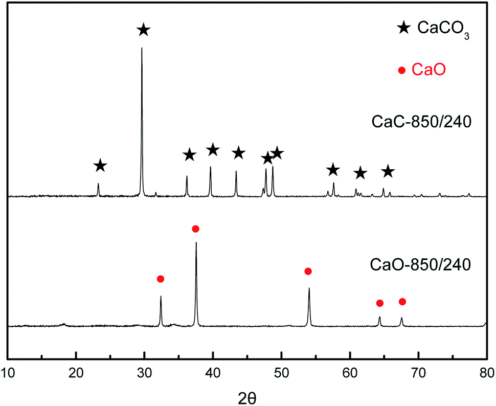
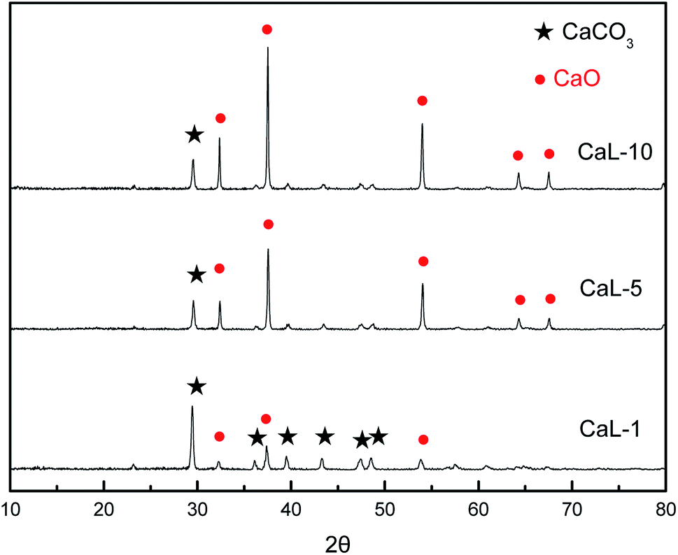
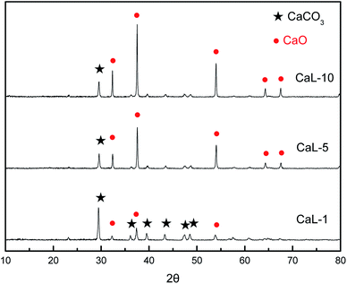
Prior to this research, the XRD of nano-CaCO3 and nano-CaO samples with the most severe heat-treatment condition of 850 °C–240 min were tested to verify the feasibility of atmosphere protection, which was shown in Fig. 2. There were only their own characteristic peaks in the spectrum of nano-CaCO3 and nano-CaO samples, indicating that the nano-CaCO3 sample did not undergo thermal decomposition and the carbonation of the nano-CaO sample did not occur either after the heat-treatment. Therefore, CO2 and N2 could meet the requirements of inert atmosphere protection during heat-treatment and this exploration of grain growth process was feasible.
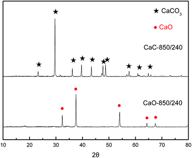 |
| | Fig. 2 XRD patterns of nano-CaCO3 and nano-CaO after heat-treatment of 850oC-240 min. | |
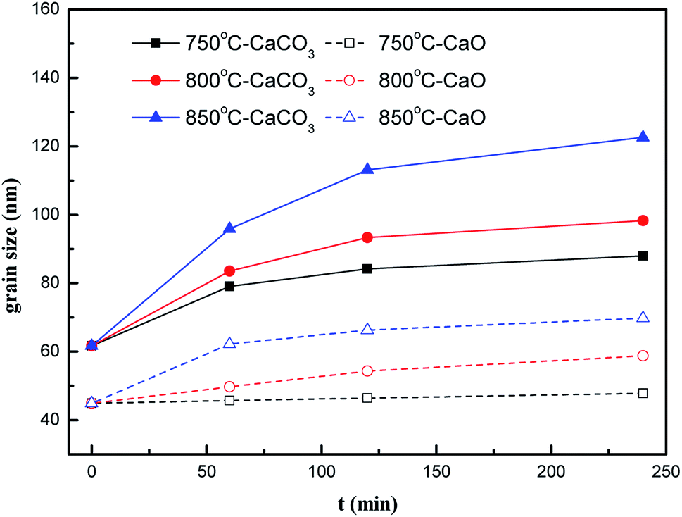
The grain sizes of nano-CaCO3 and nano-CaO obtained under the different heat-treatment conditions were shown in Fig. 3 to compare their grain growth characteristics and fit their grain growth kinetic models. It could be found that within the range of examining conditions, as the heat-treatment temperature and the time increased, the grain sizes of nano-CaCO3 and nano-CaO grew significantly. The nano-CaCO3 grain size increased from initial 61.7 nm to more than 100 nm, and the nano-CaO grain size grew from initial 44.9 nm to about 70 nm. The growth rate of both kinds of grains would remarkably develop with the increase of heat-treatment temperature. However, it gradually decreased with the prolongation of heat-treatment time, which showed a parabolic trend. In general, the growth rate of the nano-CaCO3 grain was greater than that of nano-CaO.
| |
 | (6) |
| |
 | (7) |
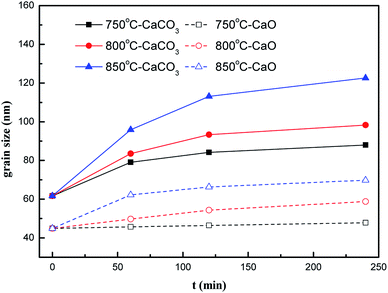 |
| | Fig. 3 Nano-CaCO3 and nano-CaO grain sizes under different heat-treatment conditions (label: temperature-sample). | |
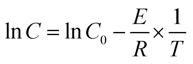
The grain growth model of solid-phase sintering19 was shown as eqn (5)–(7). First, the data in Fig. 3 were used to linearly fit Ḡ2 with t in eqn (5). The nano-CaCO3 and nano-CaO grain growth rate constants C at different heat-treatment temperatures could be obtained. Then, by linearly fitting lnC and −1/T, the nano-CaCO3 activation energy of the grain growth ECaCO3 was got as 104.8 kJ mol−1, and the nano-CaO activation energy of the grain growth ECaO was got as 212.8 kJ mol−1. It could be observed that nano-CaCO3 grains was much easier to grow than that of nano-CaO grains. In addition, according to the research of Zhu et al.,16 the activation energy of the grain growth of nano-CaO adsorbents (the same raw material as this research) through regeneration process was 120 kJ mol−1, which was located between ECaCO3 and ECaO. It illustrated that the regeneration process of adsorbents involved both nano-CaCO3 and nano-CaO grain growth, in which the influence of nano-CaCO3 was dominant.
3.2 Regenerated nano-CaO grain growth during CaCO3–CaO conversion
In this section, the effects of CaL and HtL processes on the grain size, pore structure and reactive sorption performance of nano-CaCO3 adsorbent were compared to study the relationship between CaCO3–CaO conversion and regenerated nano-CaO grain growth. The evolution of adsorbent's structural parameters during 10 cycles of CaL and HtL processes were shown in Table 2. Fig. 4 showed the composition change of the adsorbent during CaL process. There was only CaCO3 component in the adsorbent in the HtL process. However, the adsorbent included “skeleton CaO” that failed to participate in the carbonation and CaCO3 product generated by the carbonation of “active CaO” in the CaL process (Fig. 4). According to the grain sizes calculated by XRD patterns and Scherrer equation, the grain size of CaCO3 increased from 61.0 nm to 95.1 nm after high-temperature HtL process (Table 2). As the cycle time of CaL process rose up, the ratio of CaCO3 product in the adsorbent gradually declined which indicated that the loss of “active CaO” happened, while the content of “skeleton CaO” increased (Fig. 4). The thickness of the sorption product layer CaCO3 gradually diminished from 36.7 nm to 26.5 nm and the grain size of “skeleton CaO” increased from 36.1 nm to 61.5 nm (Table 2). In order to compare the grain size of regenerated CaO at the same cycle time of HtL and CaL processes, a new parameter CaO* was set to represent the total grain size of CaO in the adsorbent after regeneration of nano-CaCO3 without any further sintering. For HtL process, the value of CaO* could be directly calculated by the molar volume difference between CaCO3 and CaO (the CaCO3 molar volume was about 2.2 times as much as the CaO molar volume). CaO* for CaL process was calculated as the sum of the grain size of “active CaO” estimated by CaCO3 product and “skeletal CaO”. The calculation results of CaO* were shown in Table 2. It could be found that the values of CaO* obtained in CaL process (from 64.3 nm to 81.9 nm) were larger than those in HtL process (from 46.9 nm to 73.2 nm) at the same cycle time. The grain size of fresh nano-CaO was 44.9 nm. After 10 cycles of HtL process, the grain growth ratio was 63.0%, while after 10 cycles of CaL process, the grain growth ratio was 82.0%. It indicated that CaCO3–CaO chemical conversion could accelerate the growth of CaCO3 to some extent. But the thermal growth of nano-CaCO3 grain was still the key issue to influence the grain growth of regenerated nano-CaO.
Table 2 The values of the grain size and pore structure of adsorbents during CaL and HtL process
| Sample |
Grain size (nm) |
Specific surface area (m2 g−1) |
Pore volume (cm3 g−1) |
Mean pore diameter (nm) |
| Experimental value |
Calculated value |
| CaCO3 |
CaO |
CaO* |
| HtL-1 |
61.0 |
— |
46.9 |
1.60 |
0.007 |
20.9 |
| HtL-5 |
74.2 |
— |
57.1 |
0.96 |
0.007 |
57.5 |
| HtL-10 |
95.1 |
— |
73.2 |
0.55 |
0.006 |
83.4 |
| CaL-1 |
36.7 |
36.1 |
64.3 |
14.73 |
0.092 |
27.6 |
| CaL-5 |
29.0 |
54.0 |
76.3 |
5.45 |
0.049 |
37.1 |
| CaL-10 |
26.5 |
61.5 |
81.9 |
3.71 |
0.041 |
38.3 |
 |
| | Fig. 4 XRD patterns of adsorbents during CaL process. | |
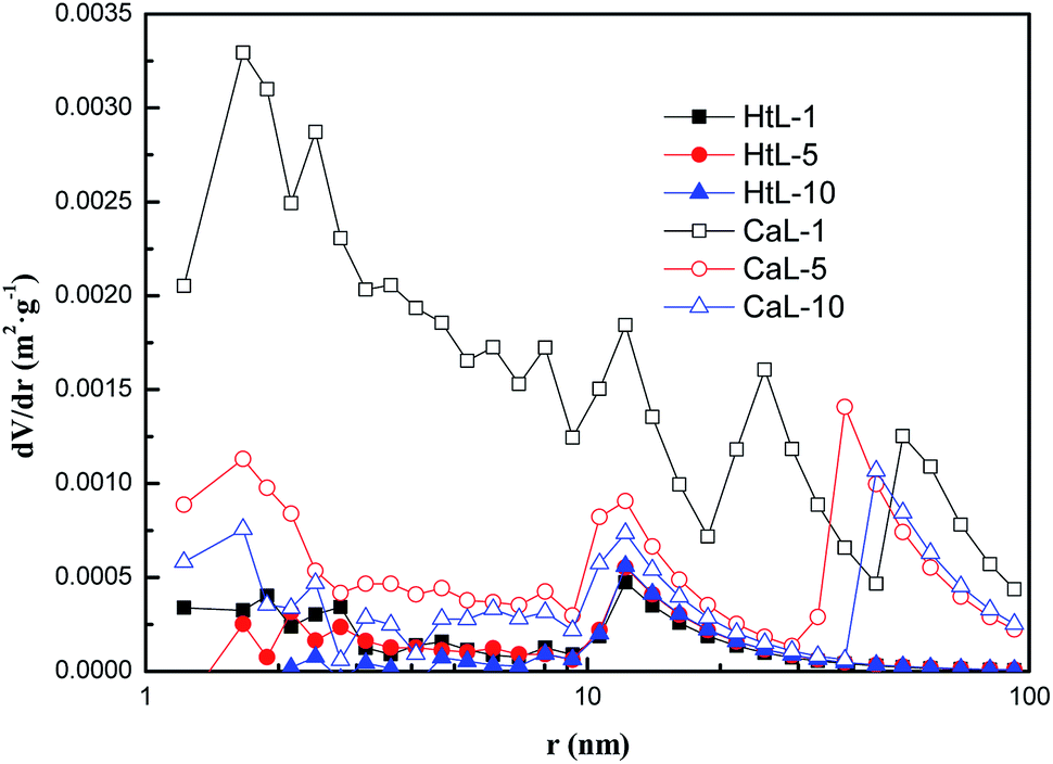
In addition, the evolution of adsorbent's pore structural parameters and pore volume distribution during 10 cycles of CaL and HtL processes were shown as Table 2 and Fig. 5 respectively. According to the results, the capillary porosity of nano-CaCO3 was very low because the specific surface area aBET (0.55–1.60 m2 g−1) and pore volume Vp (0.006–0.007 cm3 g−1) measured by the BET method were both small. After CaL cycles, aBET (3.71–14.73 m2 g−1) and Vp (0.041–0.092 cm3 g−1) were significantly improved, as the content of nano-CaO in the adsorbent increased and more capillary pores appeared (Fig. 5). HtL process had no obvious influence on the pore structure of the nano-CaCO3. However, a large amount of microporous loss happened with the prolongation of CaL cycles for the adsorbent, leading to the decrease of aBET and Vp as well as the increase of the average pore diameter ![[r with combining macron]](https://www.rsc.org/images/entities/i_char_0072_0304.gif) (from 27.6 nm to 38.3 nm).
(from 27.6 nm to 38.3 nm).
 |
| | Fig. 5 The pore volume distribution (BJH) curves of adsorbents during CaL and HtL processes. | |
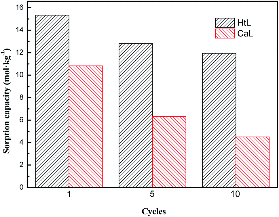
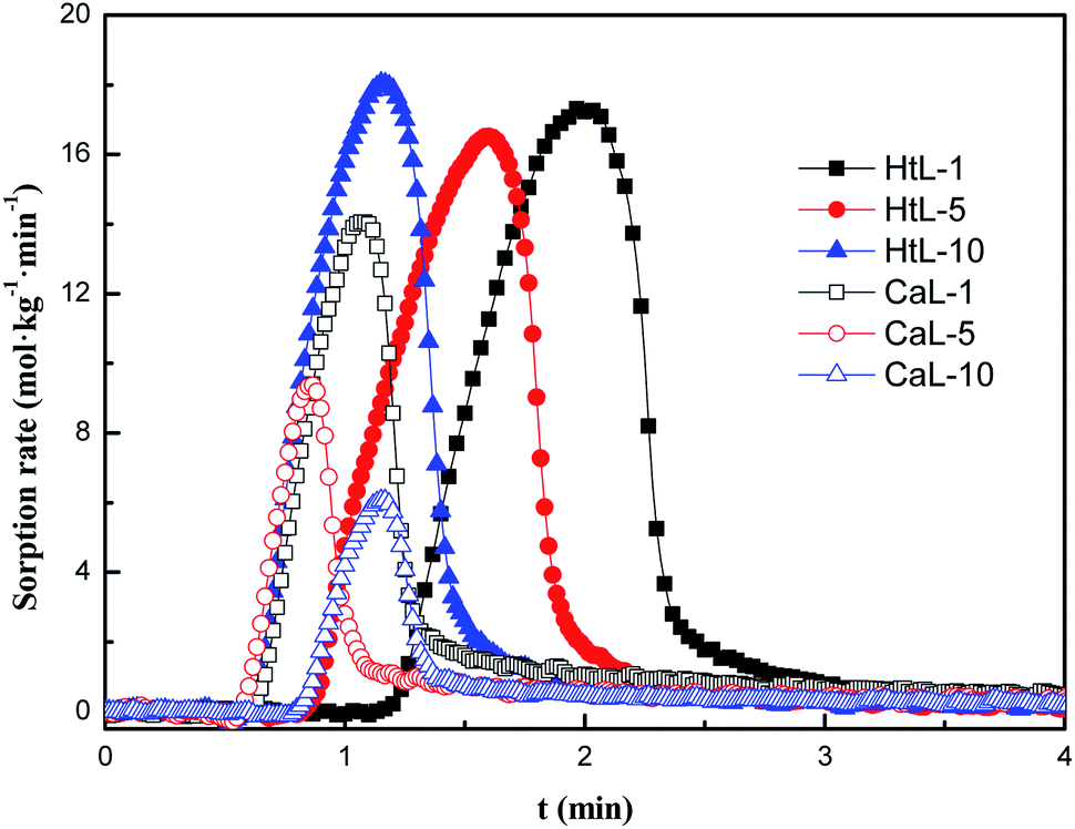
Fig. 6 and 7 depicted the sorption capacity and sorption rate of adsorbent during CaL and HtL processes. It could be seen that as the increase of the number of CaL cycles and HtL cycles, the sorption capacity and the sorption rate would obviously decrease. However, the extent of adsorbents' deactivation through HtL process (from 15.34 mol kg−1 to 11.95 mol kg−1) was less than that of CaL process (from 10.83 mol kg−1 to 4.5 mol kg−1). After the same times of cycle, the sorption capacity and sorption rate of adsorbent through HtL process were higher than that of adsorbent through CaL process.
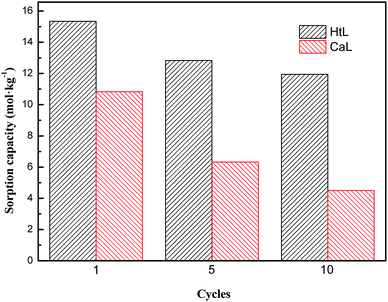 |
| | Fig. 6 The sorption capacity of adsorbents during CaL and HtL process. | |
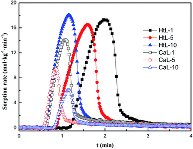 |
| | Fig. 7 The sorption rate of adsorbents during CaL and HtL process. | |
According to the above experiment results, the structural evolution of the CaCO3–CaO conversion during the CaL process could accelerate the growth of regenerated nano-CaO grain and the disappearance of micropores. It reduced the numbers of active CaO sites, so the sorption performance of the adsorbent would rapidly decay during CaL process.
3.3 The grain growth mechanism of regenerated nano-CaO in CaL
Based on the above experimental results and the SEM images of the adsorbent through CaL process (Fig. 8(a)), the grain growth mechanism of the regenerated nano-CaO was summarized in Fig. 8(b). According to the SEM image (a)-I, fresh nano-CaCO3 grains were dispersed stacked cubic microcrystals (calcite). During the first regeneration step, the grain boundaries among the nano-CaCO3 with surface contact were gradually eliminated and the grain size increased (transition state). Subsequently, the conversion between CaCO3 and CaO with a large difference in the molar volume as well as the CO2 gas flow among the grains would cause the internal microstructure of the adsorbent to rearrange constantly. The structure of nano-CaO became tighter with more capillary pores (SEM image (a)-II). Then, in the first carbonation stage, only small particle sizes' nano-CaO and the surface of large particle sizes' nano-CaO could be converted back to nano-CaCO3, which indicating the initial decline of sorption capacity. Because the molar volume of CaCO3 was bigger than that of CaO, many micropores were filled up. It resulted in more surface contact of nano-CaCO3 and created conditions for the growth of nano-CaCO3 during the next regeneration step. In the subsequent CaL processes, these steps were iteratively repeated and the proportion of “skeletal CaO” continuously increased until the micropores in the adsorbent almost disappeared (SEM image (a)-III). Finally, the growth of regenerated nano-CaO grain stopped and the sorption capacity decreased to a fairly low level.
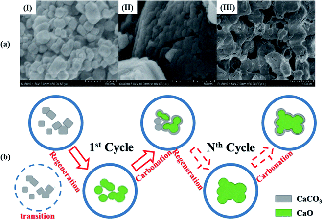 |
| | Fig. 8 (a) SEM morphology images of adsorbents: (I) new nano-CaCO3, (II) nano-CaO generated from first decomposition, (III) nano-CaO generated from 10th decomposition; (b) schematic diagram of grain growth mechanism of regenerated nano-CaO in CaL process. | |
In summary, there were two necessary conditions triggering the grain growth of regenerated nano-CaO. One was sufficiently high ambient temperature (much higher than the Tammann temperature of CaCO3), which could be called as the external factor. The other one was the surface contact of nano-CaCO3 grains, which could be called as the internal factor. Therefore, two strategies for limiting the regenerated nano-CaO grain growth was reducing the high-temperature residence time and preventing interface contact of nano-CaCO3 grains.
4. Conclusions
In CaL process, the thermal decomposition of nano-CaCO3 to produce nano-CaO was the main stage affecting the growth of regenerated nano-CaO grains, which would lead to the sintering and deactivation of adsorbents. In this work, the grain growth mechanism of the regenerated nano-CaO in CaL process was studied experimentally. By comparing the activation energy data of grain growth of nano-CaCO3 and nano-CaO, it indicated that the grain growth of nano-CaCO3 was easier during the high-temperature looping process. Moreover, the chemical conversion between CaCO3 and CaO would accelerate the sintering of adsorbents by increasing the interface contact among nano-CaCO3 grains in CaL process based on the experimental results. Among the three substeps of regeneration process of the adsorbent, the thermal growth of nano-CaCO3 grain was the key issue to influence the grain growth of regenerated nano-CaO.
Conflicts of interest
There are no conflicts to declare.
Nomenclature
| d | Average grain size, nm |
| K | Scherrer constant, 0.89 |
| λ | X-ray wavelength, 0.154 nm |
| θ | Diffraction angle, degree |
| β | FWHM of the characteristic peak in the XRD spectra |
| Ḡ | Instantaneous average grain size, nm |
| t | Heat-treatment time, min |
| Ḡ0 | Initial grain size, nm |
| C | Grain growth rate constant, nm2 min−1 |
| T | Heat-treatment temperature, K |
| E | Activation energy of the grain growth, kJ mol−1 |
| aBET | Specific surface area, m2 g−1 |
| Vp | Pore volume, cm3 g−1 |
| Average pore diameter, nm |
References
- W. S. Broecker, Science, 1975, 189, 460–463 CrossRef CAS PubMed.
- T. Shimizu, T. Hirama and H. Hosoda, et al., A twin fluid-bed reactor for removal of CO2 from combustion processes, Chem. Eng. Res. Des., 1999, 77(1), 62–68 CrossRef CAS.
- B. Feng, H. An and E. Tan, Screening of CO2 adsorbing materials for zero emission power generation systems, Energy Fuels, 2007, 21, 426–434 CrossRef CAS.
- K. Lackner, A guide to CO2 sequestration, Science, 2003, 300, 1677–1678 CrossRef CAS.
- H. Gupta and L. S. Fan, Carbonation-calcination cycle using high reactivity calcium oxide for carbon dioxide separation from flue gas, Ind. Eng. Chem. Res., 2002, 41, 4035–4042 CrossRef CAS.
- C. Han and D. P. Harrison, Simultaneous shift reaction and carbon dioxide separation for the direct production of hydrogen, Chem. Eng. Sci., 1994, 49, 5875–5883 CrossRef CAS.
- D. P. Harrison, Sorption-enhanced hydrogen production: a review, Ind. Eng. Chem. Res., 2008, 47, 6486–6501 CrossRef CAS.
- S. F. Wu, L. B. Li, Y. Q. Zhu and X. Q. Wang, A micro-sphere catalyst complex with nano CaCO3 precursor for hydrogen production used in ReSER process, Eng. Sci., 2010, 8, 22–26 Search PubMed.
- M. Gadalla, Z. Olujic, P. Jansens, M. Jobson and R. Smith, Reducing CO2 emissions and energy consumption of heat-integrated distillation systems, Environ. Sci. Technol., 2005, 39, 6860–6870 CrossRef CAS PubMed.
- Y. Kato, N. Harada and Y. Yoshizawa, Kinetic feasibility of a chemical heat pump for heat utilization of high-temperature processes, Appl. Therm. Eng., 1999, 19, 239–254 CrossRef CAS.
- S. F. Wu, Q. H. Li, J. N. Kim and K. B. Yi, Properties of a nano CaO/Al2O3 CO2 sorbent, Ind. Eng. Chem. Res., 2008, 47, 180–184 CrossRef CAS.
- A. Mackenzie, D. L. Granatstein and E. J. Anthony, Economics of CO2 capture using the calcium cycle with a pressurized fluidized bed combustor, Energy Fuels, 2007, 21(2), 920–926 CrossRef CAS.
- Z. X. Feng, Y. Zheng, L. Zhang and C. G. Zheng, Research on high temperature sintering behavior of CaO sorbent used in multi-cyclic CO2 capturing, J. Eng. Thermophys., 2009, 30, 537–539 CAS.
- P. Sun, J. R. Grace, C. J. Lim and E. J. Anthony, The Effect of CaO Sintering on Cyclic CO2 Capture in Energy Systems, AIChE J., 2007, 53, 2432–2442 CrossRef CAS.
- S. Dash, M. Kamruddin, P. K. Ajikumar, A. K. Tyagi and B. Raj, Nanocrystalline and metastable phase formation in vacuum thermal decomposition of calcium carbonate, Thermochim. Acta, 2000, 363, 129–135 CrossRef CAS.
- Y. Zhu, S. Wu and X. Wang, Nano CaO grain characteristics and growth model under calcination, Chem. Eng. J., 2011, 175, 512–518 CrossRef CAS.
- K. Chrissafis and K. M. Paraskevopoulos, The Effect of Sintering on the Maximum Capture Efficiency of CO2 Using a Carbonation/Calcination Cycle of Carbonate Rocks, J. Therm. Anal. Calorim., 2005, 81, 463–468 CrossRef CAS.
- F. Donat and R. M. Christoph, A critical assessment of the testing conditions of CaO-based CO2, sorbents, Chem. Eng. J., 2018, 336, 544–549 CrossRef CAS.
- H. Lu, E. P. Reddy and P. G. Smirniotis, Calcium oxide based sorbents for capture of carbon dioxide at high temperatures, Ind. Eng. Chem. Res., 2006, 45, 3944–3949 CrossRef CAS.
|
| This journal is © The Royal Society of Chemistry 2019 |
Click here to see how this site uses Cookies. View our privacy policy here. 
 Open Access Article
 This Open Access Article is licensed under a Creative Commons Attribution-Non Commercial 3.0 Unported Licence
 *a
*a