DOI:
10.1039/C9RA03329G
(Paper)
RSC Adv., 2019,
9, 23435-23443
Preparation and characterization of PEG/surface-modified layered double hydroxides as a new shape-stabilized phase change material
Received
4th May 2019
, Accepted 24th July 2019
First published on 29th July 2019
Abstract
A new shape-stabilized phase change material based on polyethylene glycol (PEG) and surface-modified layered double hydroxides (LDHs) was prepared by a solution impregnation method. PEG enabled thermal energy storage and release as a phase change material; 3-aminopropyl triethoxysilane (KH550) was used to modify the surface of LDHs (KH-LDHs) which then acted as a carrier to keep the solid form of the molten PEG at high temperature. The maximum weight percentage of PEG confined in the PEG/KH-LDHs composite was 55%. The detailed structures, thermal properties and UV absorption of the composite were characterized systematically by scanning electron microscopy (SEM), X-ray diffraction (XRD), Fourier transform infrared (FTIR) spectroscopy, differential scanning calorimetry (DSC), thermal gravimetric (TG) analysis and UV-vis absorption spectra. Results show that the PEG/KH-LDH composite has a suitable phase change temperature, considerable enthalpy, and good thermal stability as well as remarkable ultraviolet absorption ability. As a new shape-stabilized phase change material, the PEG/KH-LDH composite is expected to contribute to the effort of searching effective measures for thermal management of building and pavement materials.
1. Introduction
Phase change materials (PCMs) are acknowledged as an effective way to store energy, whereby energy can be absorbed and released by changing phase during melting and crystallization.1,2 Owing to high energy densities, repeatable utilization and good stabilities, PCMs have been extensively applied in many areas, such as smart building materials, solar-thermal systems, electronic devices, insulated fabrics, and so on.3–8
As a promising PCM, polyethylene glycol (PEG) has received considerable attention due to its favourable performance, including large enthalpy capacity, appropriate phase transition temperature, noncorrosive and nontoxic nature, good thermal cycling and chemical stabilities, and reasonable price.9–11 However, the commercial applicability of PEG is hampered given the fact that as a solid–liquid PCM, molten liquid PEG can easily leak out resulting in enthalpy loss during the melting process.12 To overcome this disadvantage, many attempts have been made. A shape-stabilized composite of PEG, which is developed by physical interactions between PEG and a carrier matrix, is an effective solution to avoid leakage during the solid-to-liquid phase change.13,14 In view of different carrier matrices, shape-stabilized composites of PEG could be mainly classified in two groups: organic form-stable PEG based PCMs and PEG-hybrid inorganic PCMs. The former group includes PEG-natural polymers,15,16 PEG-acrylic polymers,17 PEG-porous carbon materials (expanded graphite, activated carbon),18–20 and PEG-hybrid organic systems.21 The latter group is composed of PEG segments combining with different inorganic matter, such as silica,3,4,7–9 montmorillonite,22,23 diatomite,24–26 gypsum and clays.
As one of the important members in the clay family, layered double hydroxides (LDHs) have become popular in recent decades due to their special molecular construction and versatility. LDHs are a class of host–guest layered materials, which possess positively charged metal hydroxide basal layers with intercalated anions in the interlayer space. The general formula of LDHs is [M1−x2+Mx3+(OH)2]x+Ax/mm−·nH2O, in which M2+ and M3+ represent divalent and trivalent metal ions capable of occupying the octahedral sites and Am− represents interchangeable anions positioned in the gallery between the layers.27 The wide flexibility of metal cations and the exchange of intercalated anions during synthesis allow LDHs to be used for a variety of applications, such as catalysis,28 biological engineering,29 flame retardance, UV photostability,30,31 and hydrogenation. LDHs that are surface-modified with organic silane by covalent bonding can act as a matrix or support for guest species to obtain a series of organic–inorganic hybrid materials with various remarkable properties.32,33 For example, LDHs that are surface-modified with (3-aminopropyl) triethoxysilane (KH550) have been used for the immobilization of iron(III) porphyrins,34 adsorption of CO2,35 and immobilization of enzymes.36 However, to the best of our knowledge, very little research has focused on PEG/LDHs hybrids that used surface-modified LDHs as a matrix to shape PEG. The combination of LDHs and PEG for producing shape-stabilized PCMs is originated from the following considerations: (1) LDHs that are surface-modified with a silane coupler work to restrict the leakage of liquid PEG during melting; (2) the property of LDHs and PEG was not affected during the preparation, so the desired performance of PEG/LDHs hybrids can be obtained owing to the versatility and adjustability of LDHs' molecular structure and stored energy of PEG; (3) the preparation of LDHs can be easily achieved.36
Previous researchers have studied mixing PCM into bitumen to change the thermo-physical characteristic of bitumen pavement using the latent thermal characteristic and temperature control function of PCM.26 It has been found that aged bitumen led to the premature deterioration of pavement structure.37 For improving the applicability of PCM in building materials and bitumen pavements, we propose a promising PCMs (the PEG/surface-modified LDHs) to provide thermal regulation and improve aging resistance resulting in improved durability and extended service life. Surface-modified LDHs were used as a carrier matrix to prepare the new shape-stabilized PCMs (i.e., PEG/KH-LDHs composite) by solution impregnation methods.4 The microscopic structures, chemical compatibilities, and crystallization properties of PEG/KH-LDHs were characterized by scanning electron microscopy (SEM), Fourier transform infrared (FTIR) spectroscopy and X-ray diffraction (XRD). Thermal properties, thermal stability and UV absorption properties of PEG/KH-LDHs were measured by differential scanning calorimetry (DSC), thermogravimetric analysis (TGA) and UV-vis spectrophotometer.
2. Experimental
2.1 Materials
PEG with an average molecular weight of 2000 was purchased from Shanghai Macklin Biochemical Co. Ltd., China. MgAl-LDHs (MgAl–CO32−-LDHs with Mg/Al molar ratio 2![[thin space (1/6-em)]](https://www.rsc.org/images/entities/char_2009.gif) :1) were obtained from Dandong Songyuan Chemical Co. Ltd., China. The 3-aminopropyl triethoxysilane (KH550, 99%) was supplied by Shanghai Macklin Biochemical Co., Ltd, China. All reagents are analytical grade and were used as received without further purification.
:1) were obtained from Dandong Songyuan Chemical Co. Ltd., China. The 3-aminopropyl triethoxysilane (KH550, 99%) was supplied by Shanghai Macklin Biochemical Co., Ltd, China. All reagents are analytical grade and were used as received without further purification.
2.2 Surface modification of the MgAl-LDHs
1.0 ml KH550 was added to a three-necked flask containing a solution of ethanol and deionized water (the ratio of ethanol to deionized water = 95:5). The obtained solution was subjected to sonication for 10 min at room temperature before adding 10 g MgAl-LDHs under vigorous stirring. Then the mixture was sonicated for 30 min and was continually stirred at 90 °C in a water bath for 6 h before being filtered. The residue slurry which was denoted as KH-LDHs was washed with ethanol for three times and then dried in a vacuum oven at 120 °C for 1 h.
2.3 Preparation of the PEG/KH-LDHs composite
The solution impregnation method was adopted to prepare the PEG/KH-LDHs composite. PEG was first dissolved in anhydrous ethanol at room temperature. Then KH550-LDHs with different mass ratios were added into the solution under magnetic stirring for 4 h. A series of PEG/KH-LDHs composite were obtained by evaporating the solvent in a vacuum oven at 80 °C for 24 h, of which the mass ratios of PEG in the composites were 50%, 55%, and 60%. They were denoted as 50PEG/KH-LDHs, 55PEG/KH-LDHs, 60PEG/KH-LDHs, respectively. A PEG/LDHs composite with unmodified MgAl-LDHs was obtained with the same procedure for the comparison purpose.
2.4 Characterization
Morphological features of the PEG/KH-LDHs composites were characterized using a field emission scanning electron microscope (FESEM, Nova NanoSEM 230, FEI). The crystallization properties were investigated using powder XRD (DY5261/Xpert3, CEM, USA). The XRD patterns were collected with a scan rate of 4° min−1 in the angular range from 5° to 80° (2θ) using Cu Kα radiation (λ = 1.54 Å, wavelength) and operating at 40 kV and 100 mA. FTIR spectroscopy (Nicolet iS50, USA) was used to analyse the chemical compatibilities of the PEG/KH-LDHs composites. The FTIR spectra were obtained in wavenumber range of 400–4000 cm−1 using KBr as the dispersed phase. The phase change temperature and enthalpy of each sample were measured using DSC (DSC214, Netzsch, Germany). All measurements were conducted at constant heating and cooling rates of 5 °C min−1 under a high-purity nitrogen atmosphere in the range from 0 to 130 °C. The thermal stabilities were determined by TGA under a nitrogen atmosphere at the heating rate of 10 °C min−1; the temperature range was from 20 °C to 650 °C. The UV-vis absorption spectra were obtained at room temperature in the range from 200 to 800 nm by means of a UV-vis spectrophotometer (Cary 7000, Agilent, USA) with a slit width of 2.0 nm.
3. Results and discussion
3.1 Stabilities of the PEG/KH-LDHs composite
The synthesis schematic of a PEG/KH-LDHs composite is shown in Fig. 1. As can be seen, the KH-LDHs was used to immobilize PEG by both hydrogen bonding and surface adsorption. LDHs possess a multitude of free hydroxyls on the surface, which would lead to its hydrophilicity and the agglomeration between LDHs particles.38 However, the hydrolysis of silane coupling agents (KH550) generated Si–OH, and then covalent bonds (M–O–Si, M = Mg, Al) were formed between the surface hydroxyl groups of LDHs and hydrolysable groups (alkoxy) of KH550 through hydrolyzation, dehydration and solidification.39 Therefore, KH550 was anchored on the external surfaces of the LDHs with amino groups stretching out. When PEG was added to the KH-LDHs, N–H⋯O hydrogen bonds were formed between the oxygen atoms in the PEG chains and the surface amino groups in the KH-LDHs.4 The interactions of hydrogen bonding and surface adsorption restrained the movement freedom of the PEG chains leading to the stabilization of the PEG/KH-LDHs composite in the molten state. In addition, surface-modified LDHs effectively enhanced the dispersity and decreased agglomeration by reducing the hydroxyl groups and increasing lipophilic group on the surface of LDHs, which substantially improved the surface hydrophobicity and compatibility of LDHs, and increased homogeneity and the adsorption effect.36 All of the above characteristics provide a firm support for PEG/KH-LDHs composites as a type of promising shape-stabilized PCMs.
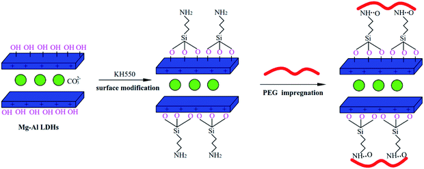 |
| | Fig. 1 Synthesis schematic of PEG/KH-LDHs composites. | |
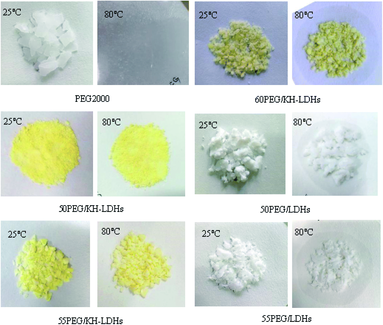
The stabilities of PEG in composite PCMs with elevated temperature from 25 °C to 80 °C are shown in Fig. 2. Diffusion-oozing circle test7,40 was carried out to determine the shape stabilities of PCMs with different PEG mass ratios. As observed, the PEG/KH-LDHs composites are light-yellow in colour, while the PEG/LDHs composites are white. There is little leakage of the melted PEG on the filter paper for the 50PEG/KH-LDHs and 55PEG/KH-LDHs when the temperature is 80 °C, which exceeds the melting point of PEG. However, exudation on the filter paper is observed in the 60PEG/KH-LDHs and PEG at 80 °C. In addition, exudation is also observed in the PEG/LDHs composite in which the MgAl-LDHs were not surface-modified by KH550. This finding demonstrates that the PEG/KH-LDHs has obtained good shape stabilities and that amino modification of the LDHs plays a key role in keeping the solid form of the PEG/KH-LDHs composite. The maximum weight percentage of PEG stabilized in the PEG/KH-LDHs composite without leakage is 55%.
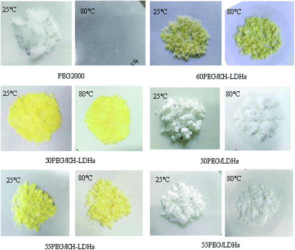 |
| | Fig. 2 Shape-stabilized property of a series of PEG based PCMs at different temperatures. | |
3.2 Morphology characterization by SEM
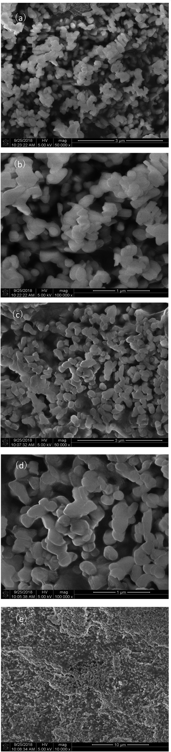
Fig. 3 shows the representative microstructural images of LDHs (a and b) and 55PEG/KH-LDHs (c–e). As can be seen, the pristine LDHs particles have sizes of approximately 200 nm with typically plate-like shapes, and smooth surface. In addition, the agglomerate state of the LDHs particles can also be clearly observed. The KH-LDHs display almost the same particles size as that of pristine LDHs, but the particles distribution is more homogeneous and the agglomeration is eliminated significantly, which can be ascribed to the decrease of hydroxyl groups on the surface of LDH during the grafting of KH550 onto the surface of LDH.38,41
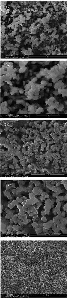 |
| | Fig. 3 SEM images of LDHs (a and b) and 55PEG/KH-LDHs (c–e). | |
With a relatively low melting point, PEG tends to melt to an amorphous state under the focus of the electron beam gun of the scanning electron microscope.42 From Fig. 3c–e, it can be seen that KH-LDHs is evenly covered by the amorphous PEG and liquid leakage isn't observed from melted PEG in 55PEG/KH-LDHs, which confirms the assumptions of the PEG/KH-LDHs as a promising shape-stabilized PCM.
3.3 Characterization by XRD
Fig. 4 presents the XRD patterns of the LDHs, PEG, KH-LDHs and 55PEG/KH-LDHs. The XRD patterns of the LDHs show a typical layered structure with high intensity reflections as (003), (006) and (009) at 11.58, 23.31, and 34.63, respectively. By using Bragg's Law, the d (003) value is calculated to be 0.78 nm, which is similar to CO32− interlayered LDHs. In the XRD patterns of pristine PEG, there are two sharp diffraction peaks at 19.16 and 23.28, which indicate that PEG has an excellent crystal structure. Compared to the LDHs, the KH-LDHs displays no new diffraction peaks, which suggests that no crystal structure changes occurred before or after modification. This finding is validated by the d(003) spacing of the KH-LDHs which is almost the same as that of the LDHs. On the other hand, this finding also indicates that the KH550 has not been intercalated into the galleries of the LDHs during the modification process. In this context, the KH550 is only able to anchor onto the –OH groups on the external surface of the LDHs by condensation. In the XRD patterns of the 55PEG/KH-LDHs, the characteristic peaks of LDHs remained at 11.58° and 23.31°, and the sharp peaks at 19.16° and 23.28° indicate that the crystalline structure of PEG is well-preserved during the preparation process. Additionally, no other impurities were detected from the XRD pattern of the 55PEG/KH-LDHs composite. This indicates that PEG has not been intercalated into the LDH's galleries and the crystal structures of the LDHs and PEG were not affected during the preparation of 55PEG/KH-LDHs.
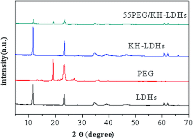 |
| | Fig. 4 XRD spectra of LDHs, PEG, KH-LDHs and 55PEG/KH-LDHs composites. | |
3.4 Characterization by FTIR
The FTIR spectra of the LDHs, PEG, KH-LDHs and 55PEG/KH-LDHs are presented in Fig. 5. For the LDHs, the broad band at 3200–3600 cm−1 can be ascribed to the stretching vibration of the –OH groups, and the weak band at approximately 1630 cm−1 is due to the bending vibration of water molecules. The sharp peak at 1370 cm−1 is attributed to the CO32−, and some low band peaks are caused by M–O (M = Mg, Al) units. The characteristic peaks of PEG2000 can be observed at 841, 946, 1113, 1147, and 2881 cm−1, and the wide vibration is centered at 3412 cm−1. It is clear that the peaks at 1113 cm−1 and 1147 cm−1 are due to the stretching vibration of C–O–C. The peaks at 946 cm−1 and 2881 cm−1 originate from the stretching vibration of –CH2. The wide vibration at 3412 cm−1 is attributed to the stretching vibration of the –OH groups. In the case of KH-LDHs, the peak found at approximately 1558 cm−1 belongs to the characteristic band of –NH2. The weak peak at approximately 1020 cm−1 is likely due to the Si–O–M (Mg, Al) which originates from the condensation between the Si–OH of KH550 and the –OH groups of LDHs. These findings indicate that KH550 has been successfully grafted onto the external surfaces of the LDHs and are consistent with those previously reported data.32–35 For the 55PEG/KH-LDHs, no obvious additional peaks are found other than the characteristic peaks of the LDHs and PEG. Nevertheless, slight shifts in some absorption peaks of PEG are observed, such as the peak of the stretching vibration of C–O–C shifted from 1113 cm−1 to 1107 cm−1 and the peaks of the stretching vibration of –CH2 moved from 946 cm−1 and 2881 cm−1 to 949 cm−1 and 2874 cm−1. This suggests that hydrogen bonding has formed between the oxygen atoms in the PEG chains and the amino groups in the KH-LDHs. Therefore, it is believed that intermolecular hydrogen bonding and physical absorption between the KH-LDHs and PEG play an important role in preventing leakage of the melted PEG.
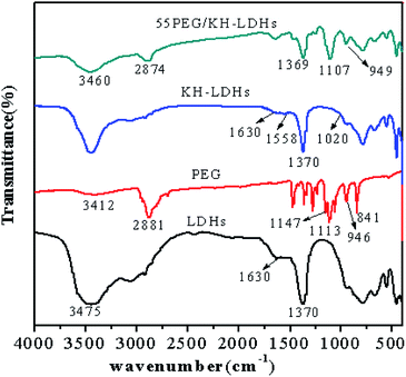 |
| | Fig. 5 FTIR spectra of LDHs, PEG, KH-LDHs and 55PEG/KHLDHs composites. | |
3.5 Thermal properties of the PEG/KH-LDHs
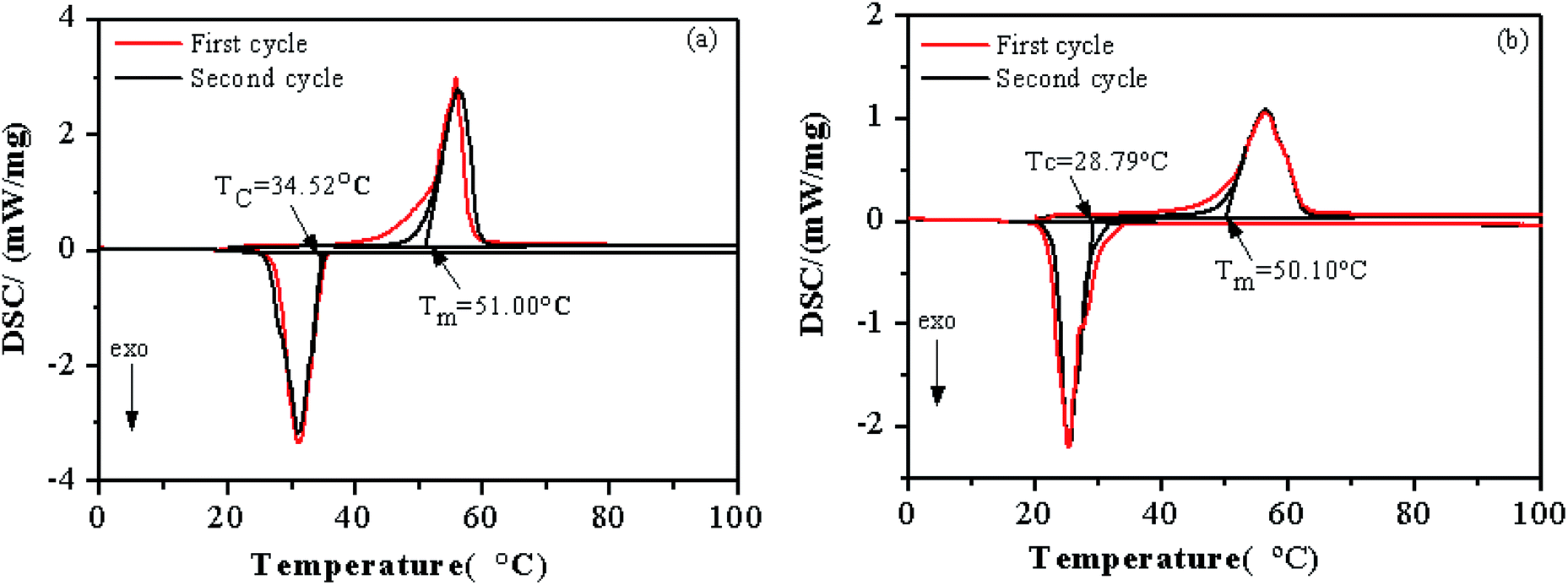
The phase change temperature and enthalpy are important thermal properties for PCMs. Fig. 6 shows the melting and solidification DSC curves of PEG and the 55PEG/KH-LDHs and Table 1 gives accordingly the thermal properties of in the two heating and cooling cycles. As can be seen from Fig. 6, the enthalpies of both the PEG and the 55PEG/KH-LDHs in the first heating and cooling cycle are higher than those in the second cycle, while the phase change temperatures of the PEG and the 55PEG/KH-LDHs in the two heating and cooling cycles are much different. The presumed reason for this difference in phase change temperature may lie in the thermal history and the water adsorbed by the samples in the first heating and cooling cycle.3,9 Hence, the data of the second cycle is closer to the actual situation of the samples.
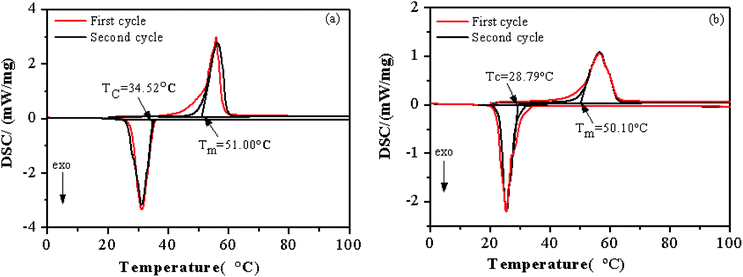 |
| | Fig. 6 DSC curves of PEG (a) and 55PEG/KH-LDHs (b) (Tc: crystallization temperature; Tm: melting temperature). | |
Table 1 Thermal properties of PEG and PEG/KH-LDHs composite
| Sample |
Melting process |
Crystallization process |
| Hm (J g−1) |
Tm (°C) |
Htheo,m (J g−1) |
Pc,m (%) |
Rm (%) |
Hc (J g−1) |
Tc (°C) |
Htheo,c (J g−1) |
Pc,c (%) |
Rc (%) |
| PEG |
185.4 |
51.00 |
|
|
|
184.8 |
34.52 |
|
|
|
| 55PEG/KH-LDHs |
100.9 |
50.10 |
101.97 |
98.9 |
1.1 |
100.0 |
28.79 |
101.64 |
98.4 |
1.6 |
| 50PEG/KH-LDHs |
88.32 |
50.42 |
92.7 |
95.3 |
4.7 |
88.02 |
27.38 |
92.4 |
95.3 |
4.7 |
Fig. 6a shows that the melting (Tm) and crystallization temperatures (Tc) of PEG are 51.00 °C and 34.52 °C, respectively. By numerical integration of the peak area, the enthalpies of melting and crystallization are 185.4 J g−1 and 184.8 J g−1, respectively. Fig. 6b indicates that the Tm and Tc of the 55PEG/KH-LDHs are 50.10 °C and 28.79 °C, respectively. After calculation, the enthalpies of melting and crystallization are 100.9 J g−1 and 100.0 J g−1, respectively. In the PEG-based PCMs, the function of storing and releasing energy is implemented by the PEG, so the mass fraction of PEG in PEG/KH-LDHs has a substantial effect on the enthalpy of this kind of PCMs. As such, the interactions between PEG and KH-LDHs led to the enthalpy loss of the PEG/KH-LDHs. The parameters including the crystallization rate of the PEG (PC) and the enthalpy loss rate of the PCMs (R) were used to characterize the enthalpy of each PCM. These parameters could be calculated by the following equations:
| PC = [Hactual/Htheo] × 100% = [Hactual/λHPEG] × 100% |
| R = [(Htheo − Hactual)/Htheo] × 100% = 1 − PC |
where
Hactual and
Htheo are the measured and the theoretical (
i.e., calculated) enthalpies of the PCM;
HPEG denotes the latent heat of the pristine PEG, and
λ is the mass fraction of PEG in the PCM. As shown in
Table 1, the
PC values of the 55PEG/KH-LDHs and 50PEG/KH-LDHs are 99% and 95%, respectively. Obviously, the values of
R for these PCMs are very small indicating slight difference between the theoretical enthalpies and actual enthalpies of PEG/KH-LDHs. This suggests that most of the PEG chains can be crystallized in the PEG/KH-LDHs PCMs.
Table 2 lists the crystallization rate of the PEG in different form-stable PCMs in the literature. It is obvious that the PEG/KH-LDHs have higher crystallization rates of PEG than other PCMs reported in the literature. In fact, the crystallization behavior of PEG in PEG/KH-LDHs is affected by two aspects. PEG can be chemically bound by hydrogen bonding or physically held through capillary forces and surface adsorption (surface areas and surface polarities) in PCMs,
2 therefore, part of the PEG molecular chains under the “partially confined state” could not experience the phase change from amorphous phase to crystal phase.
44 In the case of PEG/KH-LDHs composite, the interactions (hydrogen bonding and surface adsorption) between PEG and KH-LDHs are possibly correlated with the restricted molecular movements of part of PEG during the phase change. It decreases the enthalpy and causes a decline in phase change temperature.
3,44 On the other hand, it is believed that the KH-LDHs provide extra surfaces for the crystallization of PEG. The surfaces of KH-LDHs could act as a heterogeneous nucleation site, which could be in great favour for promoting the crystallization of PEG dispersed in the composite.
45,46 The final phase change temperature and enthalpy of PEG/KH-LDHs are the results of the dual effects mentioned above.
Table 2 shows that although the PEG concentration is low, the PEG/KH-LDHs PCMs have high crystallization rate of the PEG and could provide considerable latent heat capacity.
Table 2 The crystallization rate of the PEG in different form-stable PCMs
| Sample |
PEG maximum ratio (%) |
Melting process |
Crystallization process |
Ref. |
| Hm (J g−1) |
Pc,m (%) |
Rm (%) |
Hc (J g−1) |
Pc,c (%) |
Rc (%) |
| PEG/SiO2 |
79.3 |
151.8 |
99 |
1 |
141 |
103 |
|
7 |
| PEG2000/SiO2 |
80 |
122 |
82.0 |
18 |
118.3 |
82.9 |
17.1 |
9 |
| PEG4000/expanded graphite |
90 |
161.2 |
95.6 |
4.4 |
|
|
|
20 |
| PEG1000/diatomite |
50 |
|
|
|
82.22 |
98.6 |
1.4 |
24 |
| PEG4000/diatomite |
72.0 |
101.9 |
70.5 |
29.5 |
|
|
|
26 |
| PEG4000/expanded perlite |
67.6 |
114.7 |
85.3 |
14.7 |
|
|
|
| PEG4000/expanded vermiculite |
73.6 |
111.0 |
75.2 |
24.8 |
|
|
|
| PEG2000/SiO2 |
80 |
109.4 |
74.8 |
25.2 |
108.9 |
75.5 |
24.5 |
42 |
| PEG4000/SiO2 |
80 |
108.1 |
79.0 |
21 |
106.6 |
79.3 |
20.7 |
| PEG6000/SiO2/Al2O3 |
82.4 |
123.8 |
82.7 |
17.3 |
126.4 |
86.2 |
13.8 |
43 |
| PEG6000/SiO2 |
80 |
|
|
|
71.79 |
47.4 |
52.6 |
44 |
| PEG10000/SiO2 |
80 |
|
|
|
74.5 |
48.3 |
51.7 |
| PEG2000/KH-LDHs |
55 |
100.9 |
98.9 |
1.1 |
100.0 |
98.4 |
1.6 |
Present study |
The research of thermal properties of 55PEG/KH-LDH indicates that the enthalpies of melting and crystallization are 100.9 J g−1 and 100.0 J g−1, while the temperature of melting and crystallization are 50.10 °C and 28.79 °C, respectively. In bitumen pavements applications, PCMs that have a phase change temperature close to bitumen's softening point (about 50 °C) are suitable. The phase change temperature of the prepared 55PEG/KH-LDHs composite is 50.10 °C, so the material can be used for thermal energy storage in bitumen pavements, which can absorb the heat of pavements from the surrounding air and solar radiation during the day in summer (Tm = 50.10 °C), and release the heat at night (Tc = 28.79 °C). The higher latent heats of melting and freezing are found respectively to be 100.9 J g−1 and 100.0 J g−1 for 55PEG/KH-LDHs. Therefore, adjusting the bitumen pavements temperature can be achieved by decreasing the surface peak temperature and the amount of sensible heat released to the atmosphere. Moreover, the performance of LDHs was not affected during the preparation of PEG/KH-LDHs. In recent years, it has been reported that LDHs could be used as anti-ultraviolet aging additives to improve UV aging resistance of bitumen.37,38 Therefore, the application of PEG/KH-LDHs composite into bitumen pavements can not only regulate extreme temperatures of bitumen pavement by phase change but also improve the aging resistance of bitumen by LDHs.
3.6 Thermal stability of PEG/KH-LDHs
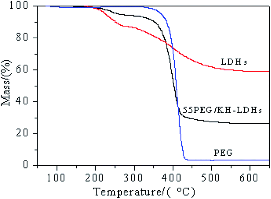
The thermal degradation curves of the LDHs, PEG and 55PEG/KH-LDHs, which were determined by TGA, are displayed in Fig. 7. The results corresponding to the characteristic temperatures and charred residues are summarized in Table 3. As shown in Fig. 7 and Table 3, only one main weight loss step is observed for PEG, which can be ascribed to the decomposition of the PEG chains at approximately 375 °C, and only 3.5% residue remained at 650 °C. The TGA diagram of LDHs displays two main weight loss steps. The first step involves a weight loss of 9.2% from approximately 50 °C to 250 °C, which is attributed to the removal of physically adsorbed and interlayer water. The second step involves a weight loss of 38.2% from approximately 250 °C to 500 °C, which is due to the dehydroxylation of the LDHs layers and the decomposition of intercalated CO3− to CO2.47 Based on the data in Table 3, the weight loss of the 55PEG/KH-LDHs at 250 °C and 500 °C is 4.3% and 72.4%, respectively, and the residual mass at 650 °C is 26.3%. The former weight loss is mainly attributed to the elimination of the interlayer water of the LDHs, which has no impact on the phase change performance of 55PEG/KH-LDHs at this stage. The latter weight loss could be caused by the decomposition of both the PEG chains and LDHs. Obviously, the thermal stability of the PEG/KH-LDHs depends on the thermal behavior of both PEG and LDHs. Therefore, based on the results shown in Fig. 7 and Table 3, it can be concluded that PEG/KH-LDHs as shape-stabilized PCMs have good thermal stability and can be used repeatedly below 250 °C.
 |
| | Fig. 7 Tg curves of PEG, LDHs and 55PEG/KH-LDHs. | |
Table 3 Thermal properties of PEG and 55PEG/KH-LDHs
| Sample |
Deg250 (%) |
Deg500 (%) |
Tmax (°C) |
Residual mass at 650 °C (%) |
| PEG |
0.6 |
96.5 |
408.2 |
3.5 |
| LDHs |
9.2 |
38.2 |
251.2 |
58.8 |
| 55PEG/KH-LDHs |
4.3 |
72.4 |
400.8 |
26.3 |
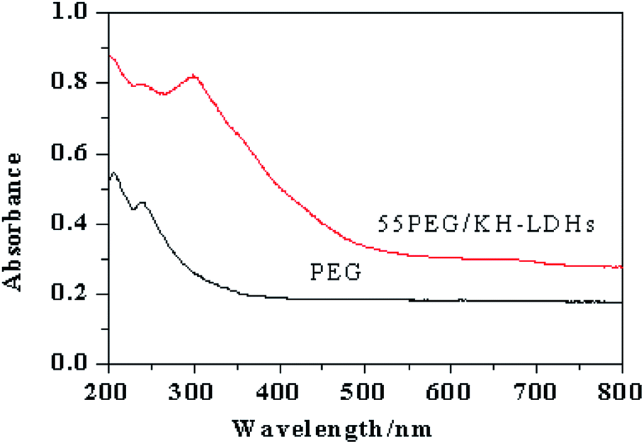
3.7 UV absorption of PEG/KH-LDHs
Fig. 8 illustrates the UV-vis absorption curves of PEG and 55PEG/KH-LDHs. In general, the total absorption strength of PEG in the ultraviolet region is weak and a weak absorption peak is observed at a wavelength of approximately 250 nm in the PEG absorption curve, For the 55PEG/KH-LDHs, a strong absorption peak appears at a wavelength of 300 nm indicating a higher absorptive ability to UV than that of pure PEG. This observation is relevant to both the inherent UV absorption properties of LDHs and the surface modification of LDHs, which has changed the guest–host interactions of LDHs.37,48 The enhanced UV absorption capacity of the PEG/KH-LDHs suggests that it could be a promising material for preventing the ultraviolet aging of outdoor buildings which is a value-added feature for its phase change property.
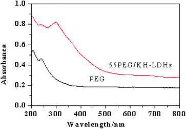 |
| | Fig. 8 UV absorption of PEG and 55PEG/KH-LDHs. | |
4. Conclusions
A new shape-stabilized PCM i.e., PEG/KH-LDHs was successfully prepared using solution impregnation method. KH550 was grafted onto the surfaces of the LDHs to obtain KH-LDHs. PEG, which served as a latent heat storage material, was incorporated into the KH-LDHs via hydrogen bonding and surface adsorption to prevent leakage of the melted PEG. The maximum weight percentage of PEG confined in the PEG/KH-LDHs without leakage was measured to be 55%. At this percentage, 55PEG/KH-LDHs showed a good chemical stability below 250 °C and exhibited a phase change temperature of 50.10 °C with a large enthalpy (Hm = 100.9 J g−1). In addition, the PEG/KH-LDHs showed a significantly enhanced ultraviolet absorption capacity than that of pure PEG. As a new kind of promising shape-stabilized phase change material, PEG/KH-LDHs can be used in constructions and bitumen pavements for peak elimination and valley filling to regulate extreme temperatures, reduce thermally-induced distresses and improve UV aging resistance, which is expected to offer significantly enhanced temperature stability and improved durability for building envelope and bitumen pavements.
Conflicts of interest
There are no conflicts of interest to declare.
Acknowledgements
This work was supported by “Minjiang Scholar” program of Fujian province, China (No. Min-jiaogao[2018]-56, GXRC-19045), the Fuzhou science and technology bureau (grant number 2018-G-78) and Natural Science Foundation of Fujian province (grant number 2019J01235). CCCC Second Harbour Engineering Co., Ltd. Fuzhou Subsidiary Company is also greatly acknowledged for the support with a joint project (No. 00501901).
References
- M. F. Demirbas, Energy Sources, Part B, 2006, 1, 85–95 CrossRef CAS.
- S. Sundararajan, A. B. Samui and P. S. Kulkarni, J. Mater. Chem. A, 2017, 5, 18379–18396 RSC.
- J. Li, L. He, T. Liu, X. Cao and H. Zhu, Sol. Energy Mater. Sol. Cells, 2013, 118, 48–53 CrossRef CAS.
- J. Wang, M. Yang, Y. Lu, Z. Jin, L. Tan, H. Gao, S. Fan, W. Dong and G. Wang, Nano Energy, 2016, 19, 78–87 CrossRef CAS.
- K. Pielichowska, and K. Pielichowski, Nanotechnology for Energy Sustainability, Wiley-VCH Verlag GmbH & Co. KGaA, 2017 Search PubMed.
- A. Sharma, V. V. Tyagi, C. R. Chen and D. Buddhib, Renewable Sustainable Energy Rev., 2009, 13, 318–345 CrossRef CAS.
- T. Qian, J. Li, H. Ma and J. Yang, Sol. Energy Mater. Sol. Cells, 2015, 132, 29–39 CrossRef CAS.
- B. Tang, M. Qiu and S. Zhang, Sol. Energy Mater. Sol. Cells, 2012, 105, 242–248 CrossRef CAS.
- L. He, J. Li, C. Zhou, H. Zhu, X. Cao and B. Tang, Sol. Energy, 2014, 103, 448–455 CrossRef CAS.
- S. Sundararajan, A. B. Samui and P. S. Kulkarni, Sol. Energy Mater. Sol. Cells, 2016, 149, 266–274 CrossRef CAS.
- P. Xi, Y. Duan, P. Fei, L. Xia, R. Liu and B. Cheng, Eur. Polym. J., 2012, 48, 1295–1303 CrossRef CAS.
- T. Kadoono and M. Ogura, Phys. Chem. Chem. Phys., 2014, 16, 5495–5498 RSC.
- H. Inaba and P. Tu, Heat Mass Transfer, 1997, 32, 307–312 CrossRef CAS.
- Q. Zhang and J. Feng, Sol. Energy Mater. Sol. Cells, 2013, 117, 259–266 CrossRef CAS.
- J. Yong, E. Ding and G. Li, Polymer, 2002, 43, 117–122 CrossRef.
- S. B. Şentürk, D. Kahraman and C. Alkan, Carbohydr. Polym., 2011, 84, 141–144 CrossRef.
- C. Alkan, A. Sari and O. Uzun, AIChE J., 2010, 52, 3310–3314 CrossRef.
- L. Feng, J. Zheng, H. Yang, Y. Guo, W. Li and X. Li, Sol. Energy Mater. Sol. Cells, 2011, 95, 644–650 CrossRef CAS.
- C. Wang, L. Feng, W. Li, J. Zheng, W. Tian and X. Li, Sol. Energy Mater. Sol. Cells, 2012, 105, 21–26 CrossRef CAS.
- W. Wang, X. Yang, Y. Fang, J. Ding and J. Yan, Appl. Energy, 2009, 86, 1479–1483 CrossRef CAS.
- K. Pielichowska, M. Nowak, P. Szatkowski and B. Macheraynska, Appl. Energy, 2016, 162, 1024–1033 CrossRef CAS.
- A. R. Bahramian, L. S. Ahmadi and M. Kokabi, Iran. Polym. J., 2014, 23, 163–169 CrossRef CAS.
- E. Onder, N. Sarier, G. Ukuser, M. Ozturk and R. Arat, Thermochim. Acta, 2013, 566, 24–35 CrossRef CAS.
- S. Karaman, A. Karaipekli, A. Sarı and A. Bicer, Sol. Energy Mater. Sol. Cells, 2011, 95, 1647–1653 CrossRef CAS.
- T. Qian, J. Li, X. Min, Y. Deng, W. Guan and L. Ning, Energy Convers. Manage., 2015, 98, 34–45 CrossRef CAS.
- J. Jin, F. Lin, R. Liu, T. Xiao, J. Zheng, G. Qian, H. Liu and P. Wen, Sci. Rep., 2017, 7, 16998 CrossRef.
- V. Rives and A. Ulibarri, Coord. Chem. Rev., 1999, 181, 61–120 CrossRef CAS.
- B. Sels, D. D. Vos, M. Buntinx, F. Pierard, A. K. Mesmaeker and P. Jacobs, Nature, 1999, 400, 855–857 CrossRef CAS.
- Z. Gu, A. C. Thomas, Z. Xu, J. H. Campbell and G. Lu, Chem. Mater., 2008, 20, 3715–3722 CrossRef CAS.
- K. František, E. Jindová, L. Kamil, K. Pavel and S. Zdeňka, Appl. Clay Sci., 2010, 48, 260–270 CrossRef.
- A. N. Ay, B. Zümreoglu-Karan, A. Temel and L. Mafra, Appl. Clay Sci., 2011, 51, 308–316 CrossRef CAS.
- A. Y. Park, H. Kwon, A. J. Woo and S. J. Kim, Adv. Mater., 2005, 17, 106–109 CrossRef CAS.
- Q. Tao, J. Yuan, R. L. Frost, H. He, P. Yuan and J. Zhu, Appl. Clay Sci., 2009, 45, 262–269 CrossRef CAS.
- F. Wypych, A. Bail, M. Halma and S. Nakagaki, J. Catal., 2005, 234, 431–437 CrossRef CAS.
- J. Wang, L. A. Stevens, T. C. Drage and J. Wood, Chem. Eng. Sci., 2012, 68, 424–431 CrossRef CAS.
- L. Dong, C. Ge, P. Qin, Y. Chen and Q. Xu, Solid State Sci., 2014, 31, 8–15 CrossRef CAS.
- S. Xu, J. Yu, W. Wu, L. Xue and Y. Sun, Appl. Clay Sci., 2015, 114, 112–119 CrossRef CAS.
- C. Zhang, J. Yu, K. Feng, L. Xue and D. Xie, Appl. Clay Sci., 2016, 120, 1–8 CrossRef CAS.
- F. Beari, M. Brand, P. Jenkner, R. Lehnert, H. J. Metternich, J. Monkiewicz and H. W. Siesler, J. Organomet. Chem., 2001, 625, 208–216 CrossRef CAS.
- B. Ma, S. Adhikari, Y. Chang, J. Ren, J. Liu and Z. You, Constr. Build. Mater., 2013, 42, 114–121 CrossRef.
- Q. Tao, H. He, T. Li, R. L. Frost, D. Zhang and Z. He, J. Solid State Chem., 2014, 213, 176–181 CrossRef CAS.
- B. Tang, J. Cui, Y. Wang, C. Jia and S. Zhang, Sol. Energy, 2013, 97, 484–492 CrossRef CAS.
- B. Tang, C. Wu, M. Qiu, X. Zhang and S. Zhang, Mater. Chem. Phys., 2014, 144, 162–167 CrossRef CAS.
- H. Yang, L. Feng, C. Wang, W. Zhao and X. Li, Eur. Polym. J., 2012, 48, 803–810 CrossRef CAS.
- L. Zhang, J. Zhu, W. Zhou, J. Wang and Y. Wang, Energy, 2012, 39, 294–302 CrossRef CAS.
- L. Xia and P. Zhang, Sol. Energy Mater. Sol. Cells, 2011, 95, 2246–2254 CrossRef CAS.
- T. Hibino, Clays Clay Miner., 1995, 43, 427–432 CrossRef CAS.
- X. Zhang, L. Zhou, H. Pi, S. Guo and J. Fu, Polym. Degrad. Stab., 2014, 102, 204–211 CrossRef CAS.
|
| This journal is © The Royal Society of Chemistry 2019 |
Click here to see how this site uses Cookies. View our privacy policy here. 
 Open Access Article
 This Open Access Article is licensed under a Creative Commons Attribution-Non Commercial 3.0 Unported Licence
 *ac
*ac