 Open Access Article
Synthesis and catalytic performance of a small crystal NaY zeolite with high SiO2/Al2O3 ratio
Liang Mu,
WeiWei Feng,
Haobin Zhang,
Xiubin Hu and
Qingyan Cui *
*
College of Chemical Engineering, Fuzhou University, Fuzhou, China. E-mail: qycui@163.com; Tel: +86-188-6011-8629
First published on 2nd July 2019
Abstract
A small crystal NaY zeolite with a high SiO2/Al2O3 ratio was successfully synthesized with seeding and without organic template, and the effects of the silicon source, aging time and Na2O seeding content on the crystal size of NaY zeolite were investigated. The synthesized samples were characterized by X-ray diffraction (XRD), scanning electron microscopy (SEM), Fourier-Transform Infrared (FT-IR) spectroscopy and N2 adsorption–desorption. The results showed that the silicon source used to prepare seeding had a great effect on the crystal size of NaY zeolite, NaY zeolite with average size of 100 nm and SiO2/Al2O3 ratio of 5.42 was obtained by using the seeding prepared with silica sol. Moreover, the crystal size of NaY zeolite decreased with an extension of the aging time and an increase of the Na2O content of seeding. The catalytic performance of small crystal Y zeolite was evaluated in the hydrocracking of vacuum gas oil (VGO), the catalyst with smaller crystal Y zeolite presented higher VGO conversion and middle distillates selectivity than those with larger ones due to its higher surface area and more amount of mesoporous.
1 Introduction
Zeolites are comprised of silicon and aluminum oxide tetrahedrons (SiO4 and AlO4−) through oxygen atom linking to form a three-dimensional network structure, in which a porous framework with micropores in the range of 2–10 Å are present. Zeolites have high surface area due to their micropores structure and exhibit acidic property depending on their compositions. Y zeolite is a kind of faujasite type zeolites with a SiO2/Al2O3 ratio larger than 3, its basic structure units, the sodalite cages, are assembled to form a spherical supercage up to 1.2 nm in the diameter, and the large cavity is 12-membered oxygen ring with a diameter of 7.1–7.3 Å.1,2 Y zeolite is widely employed as catalyst in the fluid catalytic cracking (FCC) and hydrocracking for conversion of petroleum into fuel oil based on its large amount of acid sites, thermal stability and so on.3–7Crystal size of zeolite is closely related to its properties, which have an important impact on the application. Reduction of crystal size can increase the ratio of external to internal number of atoms, thus the smaller zeolite crystals exhibit larger surface area and larger amount of activity sites. Additionally, smaller zeolite crystals with short pore channels are beneficial to the diffusion of reactant and intermediate product.8–10 Thus, small crystal zeolite used as catalyst has attracted much attention due to its high cracking activity, well catalytic selectivity and superior resistibility to coke deposition.11–14
Small crystal NaY zeolite was successfully synthesized with the assistance of organic templates, such as tetramethylammonium bromide (TMABr), tetramethylammonium hydroxide (TMAOH) and crown ether family organic, by optimizing the type and amount of organic template, composition of initial precursor suspensions and synthesis conditions.15–18 However, the usage of organic template in small crystal zeolite synthesis has several drawbacks, for instance, organic templates are expensive and non-recyclable, as well as the removal of organic templates by calcination leads to an aggregation of small crystals in large particles and the environmental pollution due to the poisonous gas emissions, in addition, the usage of organic template may result into the low yield of small crystal zeolite.11,19–21 Therefore, an approach without organics as structure directing agent is significant to synthesize small crystal Y zeolite.
There are some reports about the synthesis of small crystal Y zeolite without organic template. Mintova et al. has successfully synthesized nanosized Y zeolite with SiO2/Al2O3 ratio of 4.2 via controlling an uniform nucleation during the gel preparation.22 Zhang et al. reported that NaY zeolite with the crystal size below 400 nm was synthesized using a two-stage variable-temperature program.23 Daou et al. has synthesized zeolite Y with the crystal sizes below 30 nm and SiO2/Al2O3 about 4.4 by progressive adding of a silica source during synthesis combined with the use of prolonged aging time.24 Alhassan et al. found that nanosized zeolite Y can be synthesized in the presence of alkali metal chloride salt.25 Reinoso et al. reported that nanocrystalline NaY zeolite was synthesized at low temperature via applying ultra-assisted aging.26 Cardoso et al. synthesized nanosized faujasite crystals with the SiO2/Al2O3 ratio of 3.0 through a simple synthesis procedure.27 However, the synthesized small crystal Y zeolite had low SiO2/Al2O3 ratio as reported in the literature. It is well known that the physicochemical properties of zeolites are mainly dependent on the framework SiO2/Al2O3 ratio, and an increase of the SiO2/Al2O3 ratio in Y zeolite framework can improve its hydrothermal stability, which is beneficial to its catalytic performance.28–31 Therefore, the development of small crystal and high SiO2/Al2O3 ratio (larger than 5.0) Y zeolite synthesis is important, but there is few report about synthesis of small crystal and high SiO2/Al2O3 ratio Y zeolite in the absence of organic template.28
Seeding, acted as structure directing agent, plays an important role in the zeolite synthesis process, which has been studied. Seeding can promote zeolite nucleation and growth as well as induce the initial synthesis gel to produce target phase rather than other phases, it is in favour of improving the purity of crystal product and expanding the range of gel composition.32–35 Seeding also can decrease the crystal size and change the elemental composition of zeolite.36,37 Thompson et al. studied the effect of seeding on the zeolite synthesis, and found that seeding added into zeolite synthesis system can provide more cumulative surface area for assimilation of nutrient material from solution, thus crystallization process was accelerated with increasing amounts of seeding surface area.38 Bronic et al. reported that nuclei were produced immediately in the presence of seeding in the zeolite synthesis system on the basis of the secondary nucleation mechanism.39 However, the effects of preparation conditions of seeding on the crystals size and SiO2/Al2O3 ratio of Y zeolite have not been reported.
In this study, small crystal and high SiO2/Al2O3 ratio Y zeolite in the absence of organic template was synthesized, and the effects of preparation conditions of seeding (silicon source, aging time and Na2O content) on the crystal size and SiO2/Al2O3 ratio in Y zeolite were investigated. In addition, the catalytic performance of synthesized Y zeolite was evaluated in the hydrocracking of vacuum gas oil (VGO).
2 Experimental
2.1 NaY zeolite synthesis
NaY zeolite was synthesized in the absence of organic template via the hydrothermal method. Firstly, the seeding gel was prepared by mixing sodium aluminum (Guangfu Fine Chemical Co. Ltd.), sodium hydroxide (Beijing Modern Oriental Fine Chemical Co. Ltd.), silica sol (40 wt% SiO2 and 60 wt% H2O, Beijing Modern Oriental Fine Chemical Co. Ltd.) or sodium silicon (28 wt% SiO2, 9.1 wt% Na2O and 62.9 wt% H2O, Beijing Modern Oriental Fine Chemical Co. Ltd.) and deionized water with vigorous stirring for 1 h, and then aged at 30 °C for different time to obtain the seeding. The molar composition of seeding gel was 12–18Na2O![[thin space (1/6-em)]](https://www.rsc.org/images/entities/char_2009.gif) :
:![[thin space (1/6-em)]](https://www.rsc.org/images/entities/char_2009.gif) 1Al2O3
1Al2O3![[thin space (1/6-em)]](https://www.rsc.org/images/entities/char_2009.gif) :
:![[thin space (1/6-em)]](https://www.rsc.org/images/entities/char_2009.gif) 18SiO2
18SiO2![[thin space (1/6-em)]](https://www.rsc.org/images/entities/char_2009.gif) :
:![[thin space (1/6-em)]](https://www.rsc.org/images/entities/char_2009.gif) 320H2O.
320H2O.
The molar composition of initial precursor gel for synthesized NaY zeolite was 5Na2O![[thin space (1/6-em)]](https://www.rsc.org/images/entities/char_2009.gif) :
:![[thin space (1/6-em)]](https://www.rsc.org/images/entities/char_2009.gif) 1 Al2O3
1 Al2O3![[thin space (1/6-em)]](https://www.rsc.org/images/entities/char_2009.gif) :
:![[thin space (1/6-em)]](https://www.rsc.org/images/entities/char_2009.gif) 14.5SiO2
14.5SiO2![[thin space (1/6-em)]](https://www.rsc.org/images/entities/char_2009.gif) :
:![[thin space (1/6-em)]](https://www.rsc.org/images/entities/char_2009.gif) 300H2O. The sodium silicon, sodium aluminum, sodium hydroxide, aluminum sulfate (Beijing Modern Oriental Fine Chemical Co. Ltd.), deionized water and prepared seeding were mixed with vigorous stirring at 0 °C for 1 h, and then the precursor gel was transferred in Teflon autoclave, aged at 30 °C and hydrothermally crystallized at 95 °C. Finally, the solid sample was obtained by filtrating, washing and drying at 120 °C for 6 h.
300H2O. The sodium silicon, sodium aluminum, sodium hydroxide, aluminum sulfate (Beijing Modern Oriental Fine Chemical Co. Ltd.), deionized water and prepared seeding were mixed with vigorous stirring at 0 °C for 1 h, and then the precursor gel was transferred in Teflon autoclave, aged at 30 °C and hydrothermally crystallized at 95 °C. Finally, the solid sample was obtained by filtrating, washing and drying at 120 °C for 6 h.
2.2 Catalysts preparation
The synthesized NaY zeolite was ion-exchanged with 1.0 M NH4NO3 (Beijing Modern Oriental Fine Chemical Co. Ltd.) aqueous solution at 95 °C for 3 h, and then dried at 120 °C for 6 h and calcined at 500 °C for 4 h. The ion-exchanged process was performed for three times to obtain HY zeolite. Amorphous silica-alumina (ASA) was prepared as reported in our previous paper.5 The mixture of HY zeolite and ASA (the weight ratio of 1![[thin space (1/6-em)]](https://www.rsc.org/images/entities/char_2009.gif) :
:![[thin space (1/6-em)]](https://www.rsc.org/images/entities/char_2009.gif) 4) was used as the support of catalyst, which was extruded to form cylindrical shape. NiW/(ASA+HY) catalyst was prepared by using the incipient wetness method with aqueous solution of nickel nitrate hexahydrate and ammonium metatungstate, and settled at 25 °C for 12 h. After drying and calcination, NiW/(ASA+HY) catalyst was obtained, in which the concentration of NiO and WO3 was 7.5 and 22.5 wt%, respectively. The catalysts with Y zeolite crystal size of 100, 300 and 500 nm were designated as Cat-1, Cat-2, Cat-3.
4) was used as the support of catalyst, which was extruded to form cylindrical shape. NiW/(ASA+HY) catalyst was prepared by using the incipient wetness method with aqueous solution of nickel nitrate hexahydrate and ammonium metatungstate, and settled at 25 °C for 12 h. After drying and calcination, NiW/(ASA+HY) catalyst was obtained, in which the concentration of NiO and WO3 was 7.5 and 22.5 wt%, respectively. The catalysts with Y zeolite crystal size of 100, 300 and 500 nm were designated as Cat-1, Cat-2, Cat-3.
2.3 Characterizations
X-ray diffraction (XRD) analysis was used to identify the structure of synthesized samples, which was performed on a SIMADU XRD 6000 diffractometer with Cu Kα radiation (40 kV and 40 mA), and the XRD pattern was recorded in the 2θ range of 5 to 35°. While the SiO2/Al2O3 ratio of Y zeolite was calculated on the basis of the unit cell parameters obtained from the position of [5 5 5] reflection peak by using Breck–Flanigen equation.40 Fourier Transform Infrared (FT-IR) measurement was carried out on a MAGNAIR 560 instrument with the KBr technique to examine the framework vibration of samples. The morphology and crystal size of samples were studied with scanning electron microscopy (SEM) on a LEO435VP instrument. The crystal size distribution of synthesized Y zeolite was examined by a laser beam scattering technique on a S3500 instrument. N2 adsorption–desorption analysis was carried out on a Micromeritics ASAP 2010 instrument at −196 °C in liquid nitrogen. The surface area of Y zeolite was calculated using the Brunauer–Emmett–Teller (BET) equation, and the total pore volume was obtained from the desorption branch of the isotherm at Pi/Po = 0.995.2.4 Catalyst assessment
The hydrocracking performance of catalyst was assessed in a fixed bed reactor using-VGO as feedstock, the properties of VGO are shown in Table 1. Firstly, the catalyst was pre-sulfurized using cyclohexane solution with 2 wt% CS2 at 320 °C for 5 h, and then the hydrocracking assessment of catalyst was performed at 350 °C under H2 pressure of 8 MPa with a H2 to oil ratio of 1000 (v/v) and liquid hourly space velocity (LHSV) of 2.0 h−1. After stabilization for 5 h, the reaction product was collected and analyzed by the simulated distillation (SIMDIS ASTMD-2887), which was fractionated into naphtha (C5–C9, corresponding to <180 °C), middle distillates (C10–C22, corresponding to 180–350 °C), and residue product (C22+, corresponding to above 350 °C) on the basis of boiling point distribution. The VGO conversion, the middle distillates yield and selectivity were calculated as follows:| %C22+ conversion = (wt%C22+ in feed − wt%C22+ in product)/(wt%C22+ in feed) × 100% |
| %(C10–C22) yield = (wt%(C10–C22) in product − wt%(C10–C22) in feed)/(wt%C22+ in feed) × 100% |
| %(C10–C22) selectivity = (wt%(C10–C22) in product − wt%(C10–C22) in feed)/(wt%C22+ in feed − wt%C22+ in product) × 100% |
| Properties | |
|---|---|
| Density (20 °C) (g cm−3) | 0.91 |
| S content (μg g−1) | 25 |
| N content (μg g−1) | 335 |
| Boiling range (°C) IBP | |
| 0.5%/10% | 206/338 |
| 20%/30% | 374/397 |
| 40%/50% | 414/428 |
| 60%/70% | 444/460 |
| 80%/90% | 477/496 |
| 95% | 517 |
| FBP | 573 |
3 Results and discussion
3.1 Synthesis of small crystal and high silica NaY zeolite
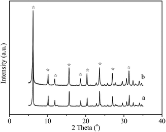
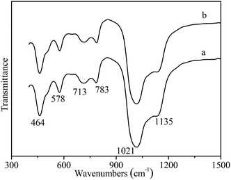
It has reported that seeding as structure directing agent plays an important role in the zeolite synthesis, adding seeding in the zeolite synthesis system can promote zeolite nucleation and growth. In this study, NaY zeolite was synthesized in the presence of seeding. Fig. 1 shows the XRD patterns of samples obtained with the seeding prepared with two kinds of silicon sources. Both samples exhibited the typical pattern of Y zeolite diffraction peaks (marked by “☆”), indicating that the synthesized sample was identified to be Y zeolite structure. FT-IR analysis can reflect the Si–O–Al linkages through the vibration band position to confirm the structure of zeolite. FT-IR spectra of synthesized samples are shown in Fig. 2. The IR band position and height of the two samples were nearly uniform. The peaks at 464, 1018 and 1139 cm−1 were attributed to the tetrahedral vibration of Y zeolite, the peaks at 713 and 787 cm−1 were related with the external linkage symmetrical stretching and the internal tetrahedral symmetrical stretching, and the peak at 578 cm−1 was assigned to double ring external linkage vibration associated with Y zeolite structure,41–43 the FT-IR analysis result indicates that Y zeolite crystal was obtained, which was consistent with the XRD result.SEM images of synthesized samples with seeding prepared with different silicon sources are shown in Fig. 3. The particles of NaY zeolite synthesized with seeding prepared with silica sol were nearly regular and not aggregated, and the sizes were about 100 nm. However, the regular and uniform particles of NaY zeolite synthesized with seeding prepared with sodium silicon were approximate 800 nm as shown in Fig. 3(b). Fig. 4 displays the particles sizes distribution of the synthesized NaY zeolite. For NaY zeolite synthesized with seeding prepared with silica sol, the particles sizes ranged from 60 to 155 nm, and the statistic average particles sizes was about 100 nm. But the particles sizes distribution was in the range of 670 to 910 nm, and the statistic average particles sizes was about 800 nm for NaY zeolite synthesized with seeding prepared with sodium silicon. The SiO2/Al2O3 ratio of NaY zeolite, with seeding prepared with silica sol and sodium silicon, was 5.42 and 5.35, respectively.
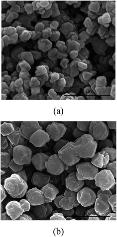 | ||
| Fig. 3 SEM images of NaY zeolite synthesized with seeding prepared with (a) silica sol and (b) sodium silicon. | ||
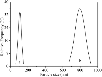 | ||
| Fig. 4 Particles sizes distribution of NaY zeolite with seeding prepared with (a) silica sol and (b) sodium silicon. | ||
It is concluded that silicon source, used to prepare seeding gel, had a strong effect on the crystal size of synthesized NaY zeolite, it may be that monopolymer silica species more easily released form silica sol than from sodium silicon tended to react with aluminum species to form nuclei precursor in the preparing seeding gel process.44 Thus the presence of more nuclei precursor in seeding gel promoted more crystal nuclei formation, which was in favour of small crystal NaY zeolite formation.
3.2 Effect of aging time of seeding
Aging time affected the amount of nuclei formed in the seeding gel preparing process, and further controlled the crystal size of synthesized zeolite. The SEM images of synthesized NaY zeolite with seeding prepared at different aging time are shown in Fig. 5. The average crystal size of NaY zeolites was about 500 nm for the seeding gel aged for 6 h, when the aging time prolonged to 24 h, the crystal sizes of NaY zeolite decreased to about 100 nm, but the crystal sizes had little change with the aging time further prolonging to 36 h. It indicates that the aging time of seeding was a crucial factor to regulate the crystal size of NaY zeolite, prolonging the aging time was beneficial to small crystal NaY zeolite formation due to more crystal nuclei formed in the seeding preparing process. | ||
| Fig. 5 SEM images of NaY zeolite with seeding prepared at different aging time (a) 6 h, (b) 12 h, (c) 24 h and (d) 36 h. | ||
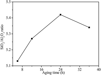
Fig. 6 shows the SiO2/Al2O3 ratio of NaY zeolite with seeding prepared at different aging time. The SiO2/Al2O3 ratio of NaY zeolite increased from 5.13 to 5.42 as the aging time of seeding extended from 6 to 24 h, but slightly decreased when the aging time prolonged to 36 h. It may be that the suitable aging time of seeding favored more silicon species inserting into nuclei, promoting the high SiO2/Al2O3 ratio NaY zeolite formation. However, much longer aging time caused some silicon species dissolved from nuclei to slightly decrease the SiO2/Al2O3 ratio of NaY zeolite.
3.3 Effect of the Na2O content of seeding
Na2O content for preparing seeding is also an important factor for the morphology of NaY zeolite. The SEM images of NaY zeolite with seeding prepared at the different molar ratios of Na2O/Al2O3 (12, 14, 16 and 18) are shown in Fig. 7. Well-crystal NaY zeolite was obtained at the different Na2O/SiO2 ratios of seeding. When the Na2O/Al2O3 molar ratio of seeding increased from 12 to 16, the crystal size of NaY zeolite exhibited a decrease trend, but the crystal size had no reduction as the Na2O/Al2O3 molar ratio of seeding further increased. It is found that higher Na2O content for preparing seeding favored the small crystal NaY zeolite synthesized, possibly due to more nuclei formation through high-polymerized silicon species depolymerizing into more low-polymerized silicon species in the high Na2O content of preparing seeding system. | ||
Fig. 7 SEM images of NaY zeolite with seeding prepared at xNa2O![[thin space (1/6-em)]](https://www.rsc.org/images/entities/char_2009.gif) : :![[thin space (1/6-em)]](https://www.rsc.org/images/entities/char_2009.gif) 1Al2O3 1Al2O3![[thin space (1/6-em)]](https://www.rsc.org/images/entities/char_2009.gif) : :![[thin space (1/6-em)]](https://www.rsc.org/images/entities/char_2009.gif) 15 SiO2 15 SiO2![[thin space (1/6-em)]](https://www.rsc.org/images/entities/char_2009.gif) : :![[thin space (1/6-em)]](https://www.rsc.org/images/entities/char_2009.gif) 300H2O: (a) x = 12, (b) x = 14, (c) x = 16 and (d) x = 18. 300H2O: (a) x = 12, (b) x = 14, (c) x = 16 and (d) x = 18. | ||
The SiO2/Al2O3 ratios of NaY zeolite with seeding prepared at the different Na2O/Al2O3 molar ratios are showed in Fig. 8. The SiO2/Al2O3 ratio of NaY zeolite decreased with an increase of Na2O/Al2O3 molar ratio in seeding, when the Na2O/Al2O3 ratio was 12, the SiO2/Al2O3 ratio of NaY zeolite reached to 5.54, but the SiO2/Al2O3 ratio of NaY zeolite decreased to 5.27 as the Na2O/Al2O3 ratio was up to 18. The lower SiO2/Al2O3 ratio of NaY zeolite obtained at the higher Na2O/Al2O3 ratio of seeding was ascribed to the existence of larger amount of low-polymerized silicon species leading to less silicon species into the framework of NaY zeolite.
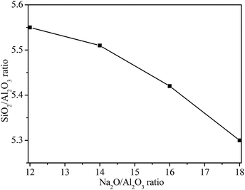 | ||
| Fig. 8 SiO2/Al2O3 ratios of synthesized NaY zeolite with seeding prepared at different Na2O/Al2O3 ratios. | ||
3.4 Texture properties
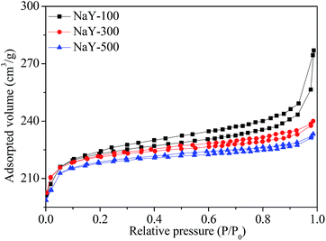
The N2 adsorption–desorption isotherms of NaY zeolites with different crystal sizes are showed in Fig. 9. The NaY zeolite with crystal sizes of 300 and 500 nm gave typical type I isotherm, with filling of the micropore at low relative pressures (P/P0 < 0.1). However, NaY zeolite with crystal size of 100 nm showed a hysteresis loop starting at P/P0 ≈ 0.2 and a steep nitrogen uptake at high relative pressure (0.9–1.0), corresponding to the type III isotherm,45 which indicates that some mesopores and macropores were formed through the aggregation of small crystal to form the interparticle voids.46 The surface area and pore structure of NaY zeolites with different crystal sizes are displayed in Table 2. Smaller crystal size NaY zeolite exhibited higher surface area, larger pore and mesoporous volumes. When the crystal size of NaY zeolite was 100 nm, the surface area reached to 728 m2 g−1, and the pore volume and mesoporous volume was 0.4142 and 0.1228 ml g−1, respectively, indicating that the reduction of crystal size of zeolite was beneficial to the enhancement of surface area and mesoporous volume, consistent with the report in the literatures.8,103.5 Catalytic performances
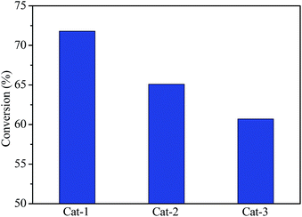
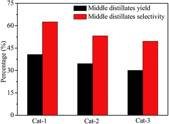
Fig. 10 shows the hydrocracking conversions of VGO over all catalysts at reaction temperature of 350 °C. The VGO hydrocracking conversion was about 72.0% for Cat-1, but the conversion decreased to 61.0% for Cat-3, indicating that the VGO conversion over the corresponding catalyst decreased with an increase of the crystal size of Y zeolite. It may be that the small crystal zeolite with short pore channel and large mesoporous volume can reduce the diffusion limitation of large molecules, as well as larger amount of available acid sites were obtained on the larger surface area, which was favorable to the improvement of VGO hydrocracking reactivity.47,48The yield and selectivity of middle distillates for all catalysts are shown in Fig. 11. Cat-1 had highest yield and selectivity of middle distillates in all catalysts, about 41.0 and 62.5%, respectively. The middle distillates yield and selectivity presented a decrease trend with an increase of the crystal size of Y zeolite, indicating that smaller crystal Y zeolite was beneficial to improve the middle distillates yield and selectivity in the hydrocracking process, possibly due to the higher dispersion of active metal species on larger surface area and the reduction of diffusion limitation of intermediate products through shorter pore channel and more mesoporous, which favored avoiding the overcracking of feedstock.
4 Conclusions
Small crystal NaY zeolite with high SiO2/Al2O3 ratio was successfully synthesized with seeding, and the effects of silicon sources, aging time and Na2O content of seeding on the crystal size and SiO2/Al2O3 ratio of NaY zeolite was investigated. It is found that the silicon source for preparing seeding played an important role on the crystal size of the synthesized NaY zeolite, when silica sol was used to prepare seeding, NaY zeolite with the average size of 100 nm and SiO2/Al2O3 ratio of 5.42 can be obtained, but NaY zeolite synthesized with seeding prepared with sodium silicon showed the average size of 800 nm and SiO2/Al2O3 ratio of 5.35. Moreover, prolonging the aging time and increasing the Na2O/Al2O3 ratio of seeding favored reducing the crystal size of NaY zeolite. In comparison of the hydrocracking performance of the catalyst containing different crystal sizes Y zeolite, Cat-1 catalyst had the VGO conversion of 72.0% and the middle distillates selectivity of 62.5% in the hydrocracking process, both were higher than those of other catalysts, indicating that the catalyst with small crystal Y zeolite presented perfect hydrocracking performance due to its especial properties.Conflicts of interest
There are no conflicts to declare.References
- M. M. Robert and N. Y. Buffalo, US Pat. No. 2882244, 1959.
- F. Delprato, L. Delmotte, J. L. Guth and L. Huve, Zeolites, 1990, 10, 546–552 CrossRef CAS.
- T. Li, H. Y. Liu, Y. Fan, P. Yuan, G. Shi, X. T. Bi and X. J. Bao, Green Chem., 2012, 14, 3255–3259 RSC.
- Y. C. Yin, L. H. Qin, X. F. Wang, G. G. Wang, J. Zhao, B. J. Liu and Y. Chen, RSC Adv., 2016, 6, 111291–111298 RSC.
- Q. Y. Cui, Y. S. Zhou, Q. Wei, G. L. Yu and L. Zhu, Fuel Process. Technol., 2013, 106, 439–446 CrossRef CAS.
- W. Q. Jiao, W. H. Fu, X. M. Liang, Y. M. Wang and M. Y. He, RSC Adv., 2014, 4, 58596–58607 RSC.
- W. W. Zhou, M. F. Liu, Q. Zhang, Q. Wei, S. J. Ding and Y. S. Zhou, ACS Catal., 2017, 7, 7665–7679 CrossRef CAS.
- L. Tosheva and V. P. Valtchev, Chem. Mater., 2005, 17, 2494–2513 CrossRef CAS.
- S. Elzey, A. Mubayi, S. C. Larsen and V. H. Grassian, J. Mol. Catal. A: Chem., 2008, 285, 48–57 CrossRef CAS.
- V. Valtchev and L. Tosheva, Chem. Rev., 2013, 113, 6734–6760 CrossRef CAS PubMed.
- L. Y. Hu, Z. K. Zhang and S. J. Xie, Catal. Commun., 2009, 10, 900–904 CrossRef CAS.
- R. P. L. Absil, A. Deptford and J. R. Katzer, US Pat. No. 5401704, 1995.
- Q. Y. Cui, Y. S. Zhou, Q. Wei, X. J. Tao and G. L. Yu, Energy Fuels, 2012, 26, 4664–4670 CrossRef CAS.
- S. F. Anis, G. Singaravel and R. Hashaikeh, RSC Adv., 2018, 8, 16703–16715 RSC.
- Q. H. Li, D. Creaser and J. Sterte, Chem. Mater., 2002, 14, 1319–1324 CrossRef CAS.
- B. A. Holmberg, H. Wang, J. M. Norbeck and Y. Yan, Microporous Mesoporous Mater., 2003, 59, 13–28 CrossRef CAS.
- R. B. Benarmas, A. Bengueddach and F. D. Renzo, Catal. Today, 2014, 227, 33–36 CrossRef CAS.
- P. Morales-Pacheco, F. Alvarez, L. Bucio and J. M. Dominguez, J. Phys. Chem. C, 2009, 113, 2247–2255 CrossRef CAS.
- H. Wang, Z. Wang and Y. Yan, Chem. Commun., 2000, 2333–2334 RSC.
- O. Larlus, S. Mintova and T. Bein, Microporous Mesoporous Mater., 2006, 96, 405–412 CrossRef CAS.
- P. Morales-Pacheco, J. M. Domínguez, L. Bucio, F. Alvarez, U. Sedran and M. Falco, Catal. Today, 2011, 166, 25–38 CrossRef CAS.
- H. Awala, J. P. Gilson, R. Retoux, P. Boullay, J. M. Goupil, V. Valtchev and S. Mintova, Nat. Mater., 2015, 14, 447–451 CrossRef CAS PubMed.
- S. Sang, Z. Liu, P. Tian, L. Qu and Y. Zhang, Mater. Lett., 2006, 60, 1131–1133 CrossRef CAS.
- M. Borel, M. Dodin, T. J. Daou, N. Bats, B. Harbuzaru and J. Patarin, Cryst. Growth Des., 2017, 17, 1173–1179 CrossRef CAS.
- H. M. Radman, A. A. Dabbawala, I. Ismail, Y. F. Alwahedi, S. Morin, M. Berthod and S. M. Alhassan, Microporous Mesoporous Mater., 2019, 282, 73–81 CrossRef CAS.
- D. Reinoso, M. Adrover and M. Pedernera, Ultrason. Sonochem., 2018, 42, 303–309 CrossRef CAS PubMed.
- T. F. Chaves, H. O. Pastore and D. Cardoso, Microporous Mesoporous Mater., 2012, 161, 67–75 CrossRef CAS.
- Y. S. Zhao, Z. Q. Liu, W. L. Li, H. H. Pa, Y. D. Liu, M. G. Li, L. J. Kong and M. Y. He, Microporous Mesoporous Mater., 2013, 167, 102–108 CrossRef CAS.
- M. I. Levinbuk, M. L. Pavlov and M. L. Kustov, Appl. Catal., A, 1998, 172, 177–191 CrossRef CAS.
- B. A. Holmberg, H. T. Wang and Y. S. Yan, Microporous Mesoporous Mater., 2004, 74, 189–198 CrossRef CAS.
- S. Ferdov, K. Tsuchiya, N. Tsunoji and T. Sano, Microporous Mesoporous Mater., 2019, 276, 154–159 CrossRef CAS.
- P. Caullet, J. Hazm, J. L. Guth, J. F. Joly and F. Raatz, Zeolites, 1992, 12, 240–250 CrossRef CAS.
- K. Suzuki and T. Hayakawa, Microporous Mesoporous Mater., 2005, 77, 131–137 CrossRef CAS.
- L. Chen, T. Xue, H. H. Wu and P. Wu, RSC Adv., 2018, 8, 2751–2758 RSC.
- I. Mochida, S. Eguchi, M. Hironaka, S. Nagao, K. Sakanishi and D. Whitehurst, Zeolites, 1997, 18, 142–151 CrossRef CAS.
- A. J. H. P. Poland and J. H. C. Hooff, Appl. Catal., A, 1992, 92, 93–111 CrossRef.
- B. W. Lu, T. Tsuda, Y. Oumi, K. Itabashi and T. Sano, Microporous Mesoporous Mater., 2004, 76, 1–7 CrossRef CAS.
- S. Gonthier and R. W. Thompson, Studies in surface science and catalysis, 1994, vol. 85, pp. 43–73 Search PubMed.
- P. K. Dutta and J. Bronic, Zeolites, 1994, 14, 250–255 CrossRef CAS.
- D. W. Breck, Zeolite molecular sieves: structure, chemistry, and use, 1974, pp. 94–97 Search PubMed.
- J. C. Jansen, F. J. Van der Gaag and H. Van Bekkum, Zeolites, 1984, 4, 369–372 CrossRef CAS.
- P. A. Jacobs, H. K. Beyer and J. Valyon, Zeolites, 1981, 1, 161–168 CrossRef CAS.
- G. Coudurier, C. Naccache and J. C. Vedrine, J. Chem. Soc., Chem. Commun., 1982, 24, 1413–1421 RSC.
- R. F. Di, A. Albizane and M. Nicolle, Stud. Surf. Sci. Catal., 1991, 65, 603–612 CrossRef.
- M. Kruk and M. Jaroniec, Chem. Mater., 2001, 13, 3169–3183 CrossRef CAS.
- B. Z. Zhan, M. A. White and M. Lumsden, Chem. Mater., 2002, 14, 3636–3642 CrossRef CAS.
- M. Firoozi, M. Baghalha and M. Asadi, Catal. Commun., 2009, 10, 1582–1585 CrossRef CAS.
- M. A. Camblor, A. Corma and A. Martinez, J. Catal., 1998, 179, 537–547 CrossRef CAS.
| This journal is © The Royal Society of Chemistry 2019 |

