DOI:
10.1039/C9RA03304A
(Paper)
RSC Adv., 2019,
9, 24003-24014
Optimization and characterization of magnetite–reduced graphene oxide nanocomposites for demulsification of crude oil in water emulsion
Received
3rd May 2019
, Accepted 27th July 2019
First published on 2nd August 2019
Abstract
Oily wastewater from the oil and gas industry negatively affects the environment. Oily wastewater typically exists in the form of an oil-in-water emulsion. Conventional methods to treat oily wastewater have low separation efficiency and long separation time and use large equipment. Therefore, a simple but effective method must be developed to separate oil-in-water emulsions with high separation efficiency and short separation times. Magnetite–reduced graphene oxide (M–RGO) nanocomposites were used as a demulsifier in this work. Magnetite nanoparticles (Fe3O4) were coated on reduced graphene oxide (rGO) nanosheets via an in situ chemical synthesis method. The synthesized M–RGO nanocomposites are environmentally friendly and can be recovered after demulsification by an external magnetic field. M–RGO characterization was performed using X-ray diffraction, Fourier transform infrared spectroscopy, X-ray photoelectron spectroscopy, field emission scanning microscopy, Raman spectroscopy, and vibrating sample magnetometry. Demulsification performance was evaluated in terms of M–RGO dosage, effects of pH, and brine concentration. The demulsification capability of M–RGO was determined based on the residual oil content of the emulsion, which was measured with a UV-vis spectrometer. The response surface method was used to determine the optimum conditions of the input variables. The optimum demulsification efficiency achieved at pH 4 and M–RGO dosage of 29 g L−1 was approximately 96%. This finding demonstrates that M–RGO nanocomposites are potential magnetic demulsifiers for oily wastewater that contains oil-in-water emulsions. Also, the recyclability of this nanocomposite has been tested and the results shown that it is a good recyclable demulsifier.
1. Introduction
The oil and gas industry is one of the most important industries in the world. Petroleum refinement has been classified as a major consumer of water. Projects conducted by oil and gas companies may generate negative impacts on the environment mainly due to waste generated from the industry. According to standard procedures set in government regulations and legislations, wastes must undergo treatment to limit the levels of contaminants before being discharged.1
Wastewater mainly originates from drilling sites, storage, and transport in the petroleum industry. The by-products of the petrochemical industry could also produce oily wastewater. Wastewater contaminates the environment. For example, water pollution directly influences groundwater resources and adversely affects public health, thereby causing death and diseases. In addition, marine pollution degrades the aquatic ecosystem. Although wastewater treatment is available at the first stage of separating oil from its constituents by applying horizontal three-phase separators, the water obtained from these separators is not completely clean. It contains residual oil that has small discrete droplets in water called oil emulsions. The water discharged from separators is generally released to the ocean from offshore platforms. The presence of pollutants must be considered to protect the environment.2
Emulsions contain two immiscible liquids and are classified as a class of disperse systems. Oil field emulsions are classified as water-in-oil (W/O) and oil-in-water (O/W) emulsions.3 Emulsion formation is due to the contact between oil and brine in the presence of sufficient mixing or an emulsifier. The effect of mixing determines the amount of shear of the fluid flow in the reservoir and bottom hole pump, the flow rate in the tubing, and other variables. Emulsion features depend on the degree of agitation, pressure, temperature and etc.4,5
In O/W emulsions, oil droplets are encapsulated by the water matrix and dispersed water. The stability of emulsification can be influenced by emulsifying agents, coalescence, temperature, droplet size distribution, and pH. Chemical, thermal, mechanical, and electrical processes or their combinations can be used to handle O/W emulsions. For other processes, filtration, pH adjustment, heat treatment techniques, and membrane separation can be used. The factors that influence demulsifier efficiency include temperature, brine composition, type of crude oil, pH, and droplet size distribution.6
The conventional demulsification technique in the petroleum industry uses chemical demulsification, where chemicals are employed to separate crude oil from water because chemicals accelerate the emulsion breaking process. Chemical demulsifiers, such as ethyl cellulose, silicone surfactant, ethylene glycol, ion liquid, ethylene oxide copolymer, and PAMAM–polyether, are commonly used. However, after demulsification, the demulsifier cannot be recovered because it is dissolved or suspended in the water.7 Moreover, most of these chemicals are toxic, costly, and not eco-friendly. Therefore, an alternative and sustainable demulsification technique is required.8
In this work, a cost-effective method and environmentally friendly material for treating oily wastewater emulsion were developed. Magnetic nanocomposites were used as a demulsifier to separate O/W emulsion. Some previous studies9,10 have shown that magnetite (Fe3O4) materials have favorable properties due to their low degree of cytotoxicity and good biocompatibility, especially during synthesis with surface coatings. Magnetite is economical, non-porous, and chemically stable. Meanwhile, graphene has high thermal conductivity, high electrical properties, large specific surface area, and high mechanical strength due to its 2D planar structure. Graphene is used to filter or adsorb oil because of its high surface area, low density, and low surface energy. Graphene-like materials, such as reduced graphene oxide (rGO), were used in this work and mixed with magnetite nanoparticles to form magnetite nanocomposites.11,12 The purpose of adding magnetite nanoparticles to rGO sheets is to prevent the restacking of rGO sheets and restrict the agglomeration of Fe3O4 nanoparticles. Loading magnetite nanoparticles on graphene sheets can enhance the adsorption capacity due to the spacing effect of graphene sheets and magnetite nanoparticles.13 Furthermore, Fe3O4 nanoparticles have a high magnetic saturation value. Thus, magnetite–reduced graphene oxide (M–RGO) after demulsification can be retrieved by applying an external magnetic field and can be recycle.
2. Materials and methods
2.1 Materials
Iron(II) chloride tetrahydrate (FeCl2·4H2O), graphene oxides (GO), sodium chloride, sodium hydroxide, deionized (DI) water, ethanol (C2H6O), ammonia solution (NH4OH, 25%), Tween 60, and Tapis crude oil were used in the experiment. All chemicals were of analytical grade purity and used without further purification. Tables 1 and 2 presented the physical and chemical properties of Tapis crude oil.
Table 1 Physical properties of Tapis crude oil
| Parameter |
Value |
| Density |
0.827 g cm−3 |
| Viscosity |
0.028 Pa s |
| Surface tension (at 30 °C) |
30.30 mN m−1 |
| Interfacial tension (at 30 °C) |
28.80 mN m−1 |
Table 2 Chemical properties of Tapis crude oil
| Parameter |
Value (wt%) |
| Saturates |
60.00 |
| Aromatics |
25.00 |
| Resins |
13.50 |
| Asphaltenes |
1.50 |
2.2 Synthesis of M–RGO
M–RGO was synthesized with an in situ chemical synthesis method.14 Nanocomposites were prepared under different stirring times of 3 and 6 h. The nanocomposites were labeled as M–RGO3 (3 h) and M–RGO6 (6 h). The mass ratio of iron salts to GO was fixed at 20![[thin space (1/6-em)]](https://www.rsc.org/images/entities/char_2009.gif) :1 during the preparation of the M–RGO nanocomposites.
:1 during the preparation of the M–RGO nanocomposites.
In the synthesis process, GO aqueous suspension was obtained through the ultrasonication of 0.2 g of GO in 200 mL of DI water for 20 min. Then, the pH of the GO suspension was adjusted to pH 11–12 by using ammonia solution under magnetic stirring. Afterward, the aqueous suspension of 4 g of FeCl2 in 100 mL of DI water was added to the GO suspension dropwise. The mixture solution underwent magnetic stirring for 3 and 6 h for M–RGO3 and M–RGO6, respectively. The black precipitate was extracted and washed with DI water through centrifugation at 7000 rpm for 10 min. The washing process was conducted three times to displace extra ammonium, and the final product was dried at 40 °C for 12 h.
2.3 Preparation of O/W emulsion
The O/W emulsion was prepared by mixing 10 wt% of Tween 60, 10 wt% of crude oil, and 80 wt% of DI water. The mother emulsion was formed by mixing the mixture for 10 min in a high-speed mixer. The mother emulsion was then diluted with brine or DI water at a ratio of 10:1. The pH of the mother emulsion was adjusted with sodium chloride and hydrochloric acid.
2.4 Characterization of M–RGO
The surface morphology of the sample was observed with a field-emission scanning microscope (FESEM, Zeiss Supra 55 VP), and the energy-dispersive X-ray (EDX) spectrum was used to determine the presence of elements in the composites. The composition information of M–RGO was determined through X-ray photoelectron spectroscopy (XPS, Thermo Scientific, K-alpha). The X-ray diffraction (XRD, X'Pert3 Powder & Empyrean, PANalytical) pattern was used to verify the formation of M–RGO. Raman spectroscopy (Horiba Jobin Yvon HR800) was performed to characterize the structural properties of M–RGO, and a vibrating sample magnetometer (VSM, DMS model 10) was used to measure the magnetic properties of M–RGO. An in situ Fourier transform infrared spectrometer with a high-vacuum purge system (FTIR, Perkin Elmer, Spectrum One) was utilized to determine the surface bonding of M–RGO.
2.5 Demulsification test
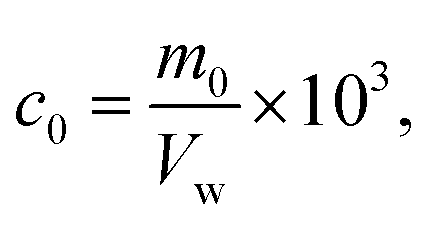
The M–RGO nanocomposites were added to O/W emulsions in a capped bottle. The bottle was shaken for 200 times to ensure good mixing at room temperature. Then, the bottle was placed at ambient conditions overnight for gravity settling. The demulsification capability of the M–RGO nanocomposites was determined by the residual oil content in the separated water after settling. The residual oil content was measured with a UV-vis spectrometer. The separated water was carefully extracted from each separated bottle. The oil concentration was obtained from the standard curve of UV-vis absorption spectra. The oil concentration in the water phase was calculated using eqn (1).| |
 | (1) |
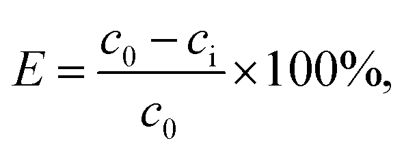
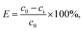
where c0 (g L−1) is the oil concentration, m0 (g) is the mass of oil in the standard curve, and Vw (mL) is the volume of the water samples. Demulsification efficiency was calculated based on the initial and residual oil contents in the water phase by using eqn (2).| |
 | (2) |
where E (%) is the demulsification efficiency and c0 and ci (g L−1) are the initial and residual oil contents of the liquid phase, respectively.
M–RGO demulsification efficiency (E) is the percentage of oil displaced from the emulsion. The factors considered in the investigation included the dosage of nanocomposites, pH of the emulsion, and brine concentration of the emulsion. Good demulsification performance results in a high demulsification efficiency percentage.
2.6 Demulsification optimization
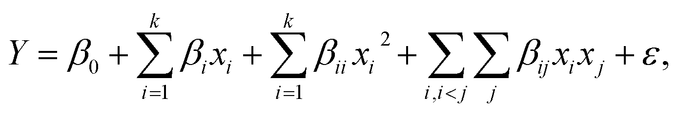
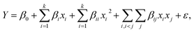
The Design Expert software was used in this study. The central composite experiment design was utilized to design the required tests for optimizing the demulsification efficiency of M–RGO. The central composite design (CCD) model was selected to analyze the experimental data with eqn (3).| |
 | (3) |
where Y represents the measured response, xi is the factor value, β0 is the offset, βi is the linear effect of the input factors, βii is the quadratic effect, βij is the cross-product term, and ε is the statistical error.
2.7 Recycle test
After demulsification test, M–RGO nanocomposites were collected using a 3000 Gs NdFeB magnet, and then repeated washed with ethanol and deionized water for 4 times alternatively to remove the attached oil. Regenerated M–RGO nanocomposites were then dried at 40 °C and reused for the next demulsification test. Nine cycles were performed to assess the reusability of M–RGO nanocomposites.
3. Results and discussion
3.1 XRD analysis
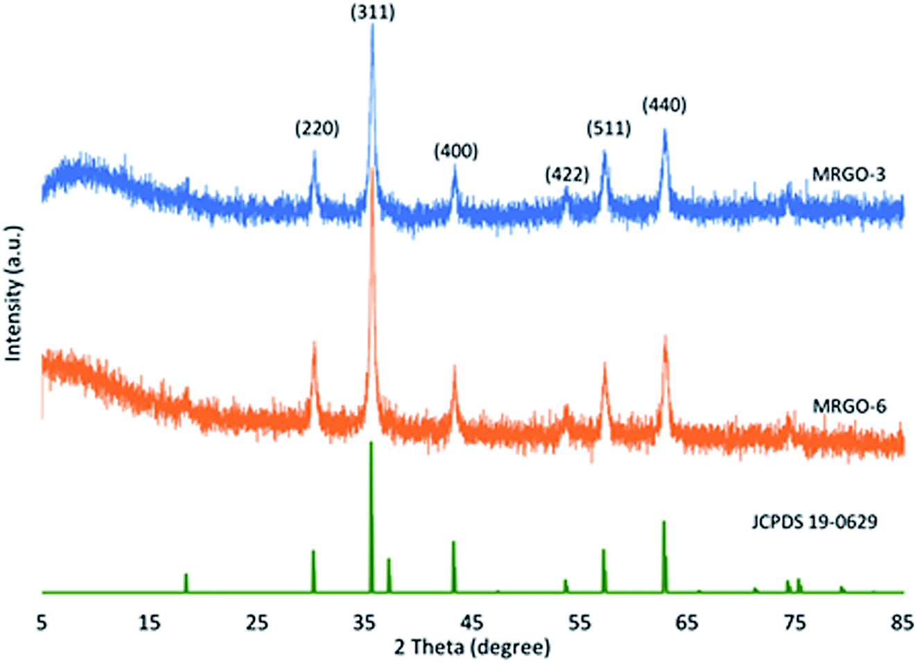
XRD characterization was performed to investigate the structural and phase information of M–RGO3 and M–RGO6. Fig. 1 shows the XRD patterns of M–RGO3 and M–RGO6. Six diffraction peaks were observed at 2θ = 30.2°, 35.6°, 43.3°, 53.7°, 57.3°, and 62.8°; these diffraction peaks corresponded to diffraction indices of (220), (311), (400), (422), (511), and (533), respectively. The peaks showed the characteristics of Fe3O4 (JCPDS card no. 19-0629).15 The results suggest that Fe3O4 nanoparticles were deposited on rGO. The weak broad diffraction peak for M–RGO3 at 2θ = 10.4° was assigned to (001), which is the peak of GO. This peak at 10.4° indicates the presence of trace amount of GO in M–RGO3. However, the broad diffraction peak of M–RGO6 at 2θ = 10.4° disappeared, which indicates the complete reduction of GO. GO was reduced to rGO, and Fe3O4 was loaded on the rGO nanosheets. The crystalline size was calculated from the width of the highest diffraction line (311) by using the Debye–Scherrer equation.16 The crystalline sizes of the Fe3O4 nanoparticles attached on GO nanosheets for M–RGO3 and M–RGO6 were approximately 23.70 and 23.71 nm, respectively. The crystalline sizes for both samples were nearly the same, indicating that the synthesis stirring time of M–RGO did not affect the crystalline size of Fe3O4 nanoparticles. The XRD patterns of M–RGO6 indicate that the M–RGO nanocomposites were successfully synthesized, and the sharp peaks reveal the good crystalline phase of M–RGO6.
 |
| | Fig. 1 XRD patterns of M–RGO3 and M–RGO6. | |
3.2 FTIR analysis
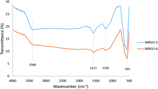
The FTIR spectra were used to characterize the M–RGO nanocomposites and confirm their chemical structure. The FTIR spectra of M–RGO3 and M–RGO6 are shown in Fig. 2. The peak at approximately 3368 cm−1 originated from the –OH stretching vibration of GO.17 The absorption peak at approximately 1571 cm−1 belonged to the skeletal vibration of GO. The vibrational band located at approximately 1205 cm−1 was assigned to C–O stretching vibrations of the epoxy group. The sharp peak at approximately 565 cm−1 was attributed to the Fe–O vibrations of Fe3O4. The presence of Fe–O vibration peaks indicates that Fe3O4 nanoparticles were successfully stacked on the surface of rGO sheets. The presence of Fe3O4 nanoparticles was further confirmed by FESEM analysis. In addition, the absorption peaks of M–RGO3 at around 3368, 1571, and 1205 cm−1 were much stronger than those of M–RGO6. This finding indicates that additional carbon functional groups existed on the surface of M–RGO3. In other words, the surface of M–RGO3 was not fully covered by Fe3O4 nanoparticles.
 |
| | Fig. 2 FTIR spectra of M–RGO3 and M–RGO6. | |
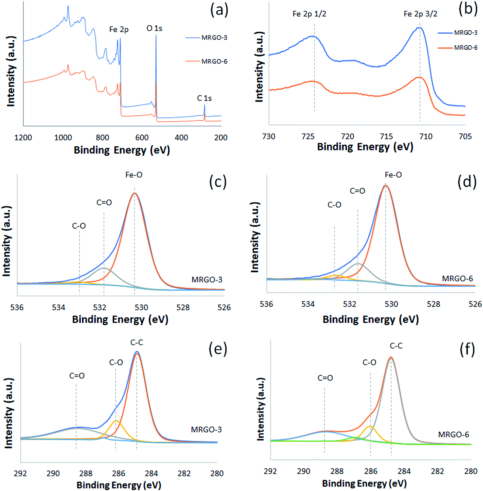
3.3 XPS analysis
XPS was performed to analyze the chemical state information of the composition of M–RGO3 and M–RGO6. The results are presented in Fig. 3. In Fig. 3a, the binding energies of peaks located at 255, 530, and 711 eV are attributed to C 1s, O 1s, and Fe 2p, respectively. In Fig. 3b, the Fe 2p spectrum shows two peaks at 711 and 725 eV corresponding to Fe 2p3/2 and Fe 2p1/2, respectively.18 The Fe 2p peaks indicate the formation of the Fe3O4 phase in GO sheets.13 This finding is also supported by the O 1s spectrum (Fig. 3c and d) at the peak of 530 eV, which indicates that Fe–O is the binding energy of oxygen in Fe3O4. Another peak in the O 1s spectrum located at 532 eV is attributed to the residual C![[double bond, length as m-dash]](https://www.rsc.org/images/entities/char_e001.gif) O group over the GO sheets. The insignificant peak at 533 eV is due to the oxygen-containing functional group from graphene. As shown in Fig. 3e and f, the deconvoluted C 1s carbon spectrum has three peaks. The main peak is located at 285 eV, which denotes non-oxygenated carbon (C–C). The peaks at 286 and 289 eV are assigned to C–O (alkoxy and epoxy) and CO groups, respectively.
O group over the GO sheets. The insignificant peak at 533 eV is due to the oxygen-containing functional group from graphene. As shown in Fig. 3e and f, the deconvoluted C 1s carbon spectrum has three peaks. The main peak is located at 285 eV, which denotes non-oxygenated carbon (C–C). The peaks at 286 and 289 eV are assigned to C–O (alkoxy and epoxy) and CO groups, respectively.
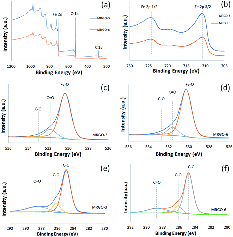 |
| | Fig. 3 XPS spectrum. (a) Wide scan of M–RGO3 and M–RGO6, (b) Fe 2p spectrum of M–RGO3 and M–RGO6, (c) O 1s spectrum of M–RGO3, (d) O 1s spectrum of M–RGO6, (e) C 1s spectrum of M–RGO3, and (f) C 1s spectrum of M–RGO6. | |
3.4 FESEM analysis
Fig. 4 shows the surface morphology of the M–RGO nanocomposites. Fig. 4a and b indicate that the Fe3O4 nanoparticles were uniformly distributed on the rGO layers with a small size and high density. GO formed a rough surface because of the crumpled structure, which provided nanoparticles with increased active surface area for decoration.19 The Fe3O4 nanoparticles were nearly spherical in shape and dispersed well on the rGO sheets. However, aggregation of nanospheres, which refers to the in situ growth of Fe3O4 nanoparticles followed by the interaction between hydroxyl or carboxylate groups and ferrous or ferric ions, was observed.20 Compared with Fig. 4a, Fig. 4b shows more Fe3O4 nanoparticles attached on the rGO sheets. This phenomenon is due to the long stirring time of M–RGO6 and the stacking of additional Fe3O4 nanoparticles on the rGO sheets. The morphology is correlated well with the results of VSM, where M–RGO6 leads to increased saturation magnetization. According to the FESEM images, the average particle sizes of M–RGO3 and M–RGO6 were 37.87 and 37.26 nm, respectively. The average nanoparticle sizes for both samples were almost the same. This finding indicates that the synthesis stirring time of M–RGO did not affect the size of Fe3O4 nanoparticles coated on the rGO sheets. A histogram of the Fe3O4 nanoparticle sizes is shown in Fig. 5.
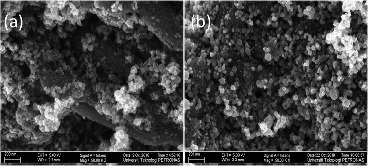 |
| | Fig. 4 FESEM image of (a) M–RGO3 and (b) M–RGO6. | |
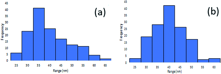 |
| | Fig. 5 Fe3O4 nanoparticles sizes histogram of (a) M–RGO3 and (b) M–RGO6. | |
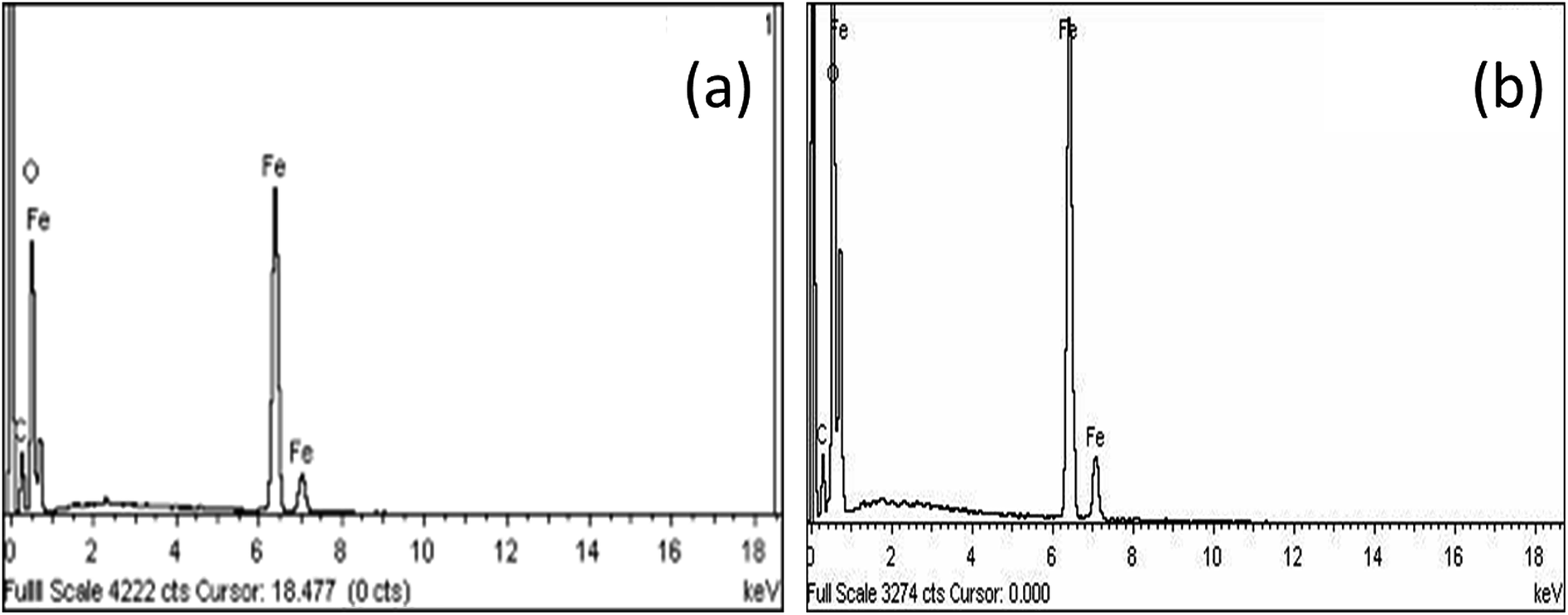
Fig. 6 shows the EDX spectroscopy analyses of the elemental compositions of M–RGO3 and M–RGO6. The spectrum of the particles revealed the presence of Fe, O, and C, and the details of the spectrum are shown in Table 3. For M–RGO3, the weight percentages of C, O, and Fe were 15.50%, 30.75%, and 53.75%, respectively, whereas those for M–RGO6 were 14.9%, 30.94%, and 54.16%, respectively. The weight percentage of iron was higher than that of carbon, indicating that the Fe3O4 nanoparticles were successfully deposited on the rGO sheets. The atomic ratios of M–RGO3 and M–RGO6 were 0.75 and 0.78, respectively. The Fe/C atomic ratio shows that M–RGO6 has a higher iron content than M–RGO3. The results are in good agreement with the FESEM image shown in Fig. 4.
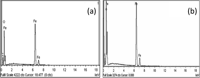 |
| | Fig. 6 EDX spectra of (a) M–RGO3 and (b) M–RGO6. | |
Table 3 EDX spectrum analysis of M–RGO3 and M–RGO6
| Sample |
Element |
Weight (%) |
Atomic (%) |
Atomic ratio 
|
| M–RGO3 |
C |
15.50 |
30.92 |
0.75 |
| O |
30.75 |
46.03 |
| Fe |
53.75 |
23.05 |
| M–RGO6 |
C |
14.90 |
29.94 |
0.78 |
| O |
30.94 |
46.66 |
| Fe |
54.16 |
23.40 |
3.5 Raman analysis
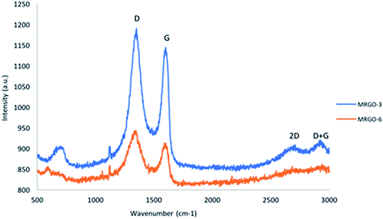
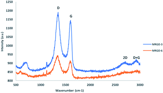
Raman spectroscopy has two defined peaks called D and G bands. According to Fig. 7, the Raman spectra (520.70 nm excitation) of M–RGO show peaks at approximately 1347 and 1598 cm−1. The G band corresponds to the vibration of sp2 carbon atoms, and the D band correlates to the vibrations of the sp3 carbon atom arrangement of disordered graphene. The 2D band has second-order Raman features. The position and multilayer of the 2D band can be used to determine the number of layers of rGO sheets.21 According to the results of M–RGO3, the Raman spectra of the 2D band at approximately 2700 cm−1 indicate the stacking number of the graphene sheet layer. According to Akhavan et al., the intensity ratios (I2D/IG) of single-, double-, triple-, and multi-layer graphene are >1.6, approximately 0.8, approximately 0.30, and approximately 0.07, respectively.22 With Fig. 7, the intensity ratio (I2D/IG) of M–RGO3 was determined to be approximately 0.79, indicating that the graphene sheet of M–RGO3 is a double-layer structure. Meanwhile, the D band intensity of M–RGO3 significantly increased compared with that of M–RGO6. This finding implies that the size of in-plane sp2 decreased and sp3 carbon increased on the graphene surface due to ultrasonic exfoliation and extensive oxidation. The combination D + G bands caused by disorder is displayed at approximately 2920 cm−1 (ref. 23). The results indicate that M–RGO3 contained randomly arranged and disordered graphene flakes. However, on the basis of the Raman spectra of M–RGO6, no significant peaks were observed for 2D and D + G bands because the Fe3O4 nanoparticles were fully distributed on the graphene sheets. The integral intensity ratio (ID/IG) was used to measure the disorder of the sample. The integral intensity ratio (R) of M–RGO3 (1.04) was slightly higher than that of M–RGO6 (1.03). These results indicate that M–RGO3 had slightly high localized sp3 defects in sp2 hybridization under the reduction of exfoliated GO.
 |
| | Fig. 7 Raman spectra of M–RGO3 and M–RGO6. | |
3.6 VSM analysis
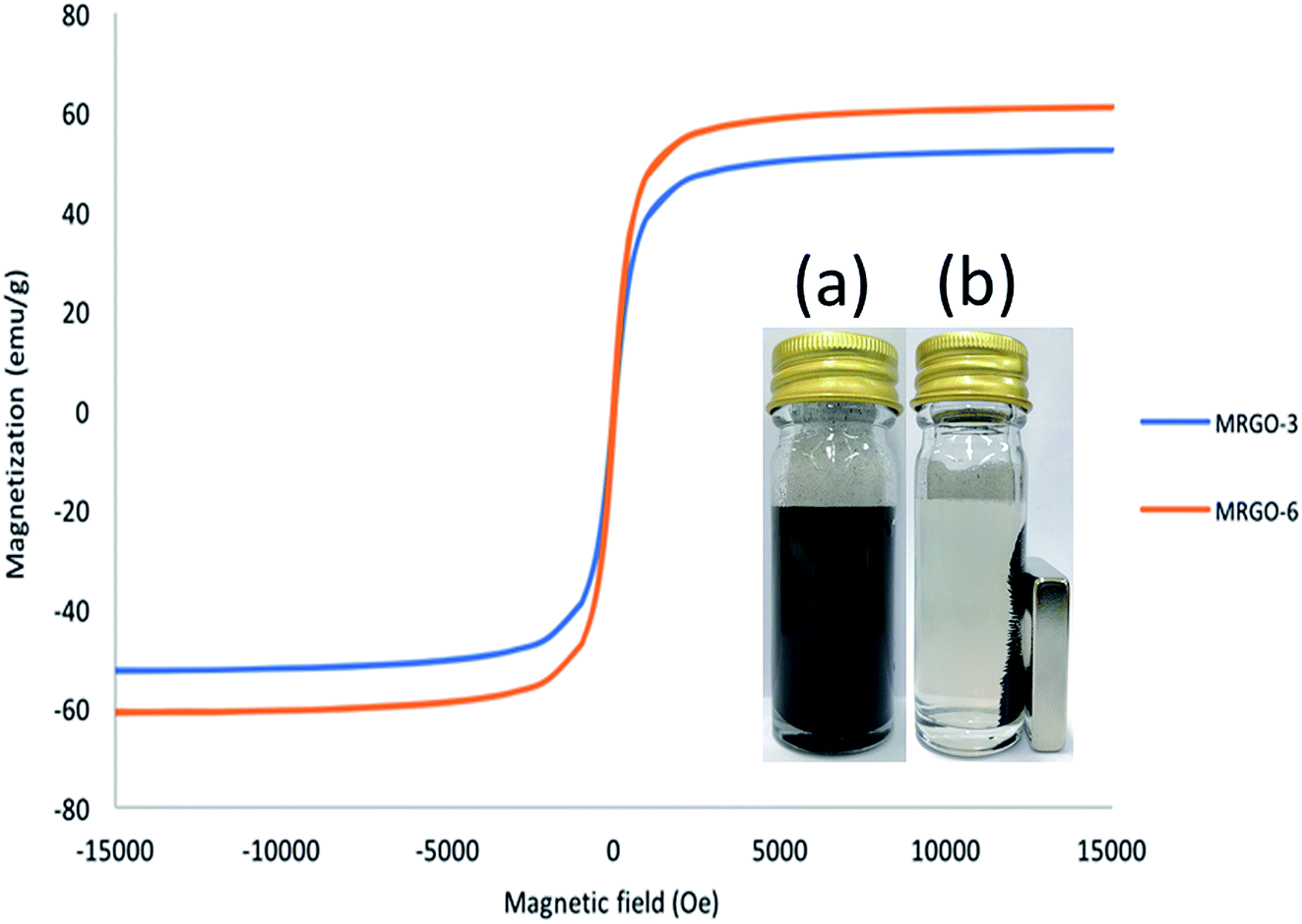
The magnetic properties of M–RGO3 and M–RGO6 were investigated via VSM at room temperature. The magnetization hysteresis curve was recorded at 300 K and is presented in Fig. 8. The saturation magnetization (Ms), coercive field (Hc), and remanence (Mr) for M–RGO3 and M–RGO6 are summarized in Table 4. The obtained hysteresis curve indicates that M–RGO exhibited a superparamagnetic character. The saturation magnetization (Ms) values were 52.4 and 61.0 emu g−1 for M–RGO3 and M–RGO6, respectively. The Ms values for both samples were lower than that of pure Fe3O4 nanoparticles (75.3 emu g−1)24 because of the small-size nanoparticles and the presence of rGO. The saturation magnetization of M–RGO6 was higher than that of M–RGO3 due to the increased Fe3O4 nanoparticles attached on rGO sheets resulting from the long stirring time. A long magnetic stirring time results in increased Fe3O4 nanoparticles. However, both M–RGOs exhibited strong magnetization, which can be manipulated by an external magnetic field that satisfies the need for magnetic separation after demulsification.
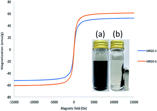 |
| | Fig. 8 Magnetic hysteresis loops of M–RGO3 and M–RGO6. The inset picture in figure is a photograph for the magnetic separation–redispersion process of M–RGO6 (a and b). | |
Table 4 Magnetic properties of M–RGO3 and M–RGO6 at 300 K
| Sample |
Hc (Oe) |
Mr (emu g−1) |
Ms (emu g−1) |
| M–RGO3 |
25.63 |
1.92 |
52.5 |
| M–RGO6 |
33.85 |
3.40 |
61.1 |
3.7 Selection of the demulsifier and characterization of O/W emulsion
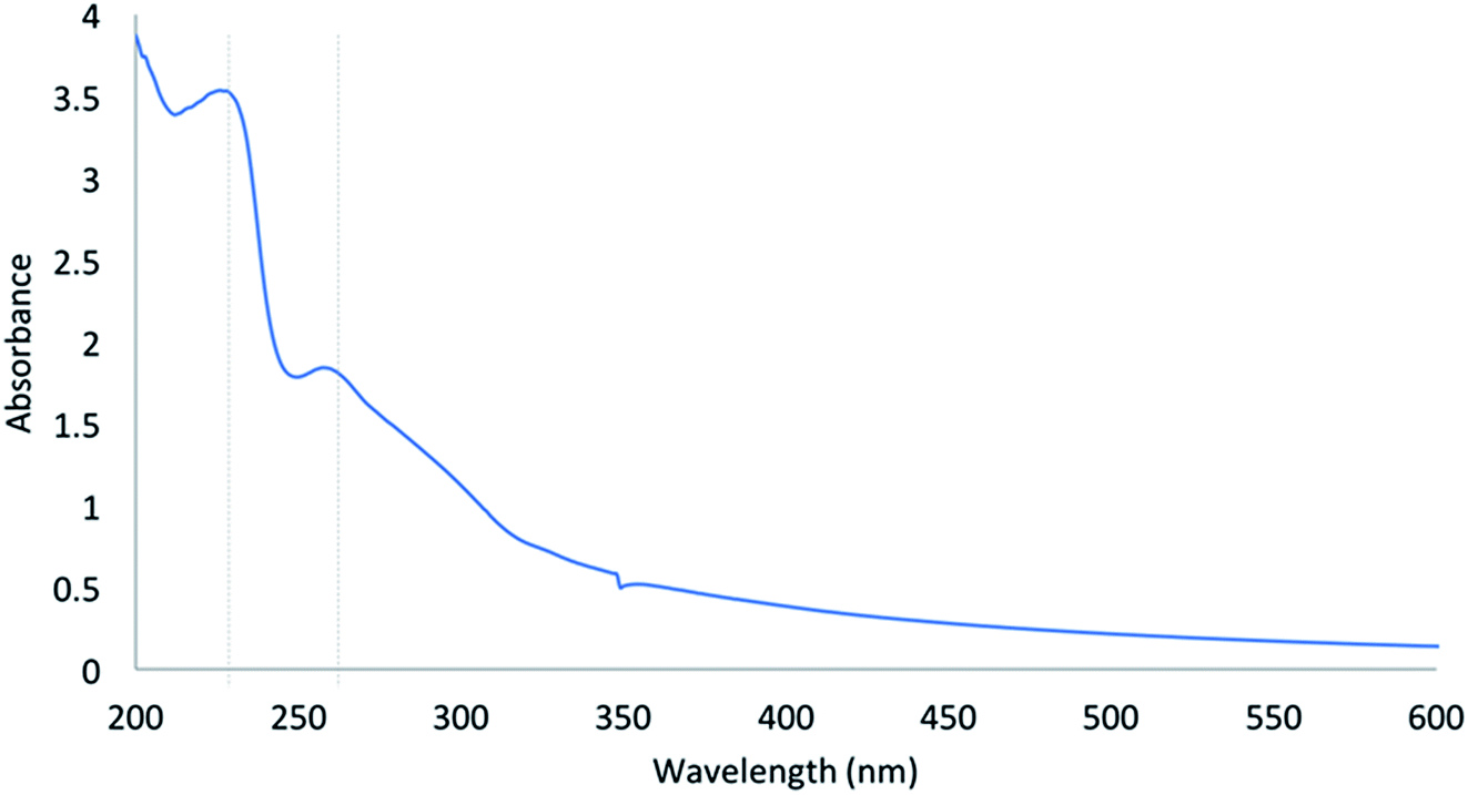
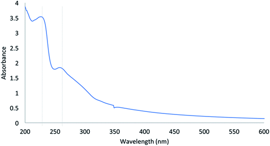
After the characterization results of two samples had been prepared, M–RGO6 was selected as the demulsifier to destabilize the interfacial tension of O/W emulsion. The reference O/W emulsion was observed for more than 24 h to confirm the absence of evident phase separation. Fig. 9 shows the UV-vis spectrum of the control sample O/W emulsion. As shown in the figure, the UV-vis absorption spectrum has two characteristic absorption peaks. The standard O/W emulsion has a maximum absorption peak located at approximately 230 nm due to the aromatic C–C bonds of π → π* transitions and a shoulder at approximately 260 nm corresponding to n → π* transitions of CO bonds.23 The absorption peak at 230 nm with high intensity was selected to analyze the demulsification efficiency.
 |
| | Fig. 9 The UV-vis absorption spectrum of the control sample O/W emulsion. | |
3.8 Optimization of the demulsification process
Demulsification tests were conducted at various demulsifier dosages, pH values, and brine concentrations. The optimum condition of M–RGO for the demulsification of the O/W emulsion was obtained with the response surface method (RSM) based on the experimental results of CCD. CCD was designed to investigate the effect of three factors at two levels (high, +1 and low, −1) and six central points (coded level 0). The factor levels and process factors of the M–RGO demulsifier are shown in Table 5, and Table 6 shows the CCD matrix design arrangement and experimental results for M–RGO6.
Table 5 Analytical factors and levels for M–RGO6 in RSM
| Variables |
Factor |
Coded levels |
| −1 |
0 |
+1 |
| Dosage (g L−1) |
A |
25 |
27.5 |
30 |
| pH |
B |
2 |
3 |
4 |
| Brine concentration (g L−1) |
C |
30.0 |
32.5 |
35 |
Table 6 Design arrangement and experimental results for M–RGO6
| Run |
Input variable |
Efficiency (%) |
| A |
B |
C |
Actual |
Predicted |
| 1 |
−1 |
−1 |
−1 |
78.43 |
76.17 |
| 2 |
1 |
−1 |
−1 |
86.63 |
89.92 |
| 3 |
−1 |
1 |
−1 |
80.84 |
86.62 |
| 4 |
1 |
1 |
−1 |
90.71 |
91.94 |
| 5 |
−1 |
−1 |
1 |
72.65 |
73.27 |
| 6 |
1 |
−1 |
1 |
91.63 |
87.69 |
| 7 |
−1 |
1 |
1 |
90.26 |
88.81 |
| 8 |
1 |
1 |
1 |
90.7 |
94.8 |
| 9 |
−1.682 |
0 |
0 |
77.49 |
76.78 |
| 10 |
1.682 |
0 |
0 |
95.27 |
93.38 |
| 11 |
0 |
−1.682 |
0 |
72.23 |
74.48 |
| 12 |
0 |
1.682 |
0 |
94.10 |
89.24 |
| 13 |
0 |
0 |
−1.682 |
97.13 |
93.24 |
| 14 |
0 |
0 |
1.682 |
91.92 |
93.21 |
| 15 |
0 |
0 |
0 |
92.91 |
96.07 |
| 16 |
0 |
0 |
0 |
96.96 |
96.07 |
| 17 |
0 |
0 |
0 |
92.69 |
96.07 |
| 18 |
0 |
0 |
0 |
96.91 |
96.07 |
| 19 |
0 |
0 |
0 |
97.57 |
96.07 |
| 20 |
0 |
0 |
0 |
98.95 |
96.07 |
3.8.1 Analysis of variance and model fitting. Analysis of variance (ANOVA) was performed to determine significant differences between the independent variables. Statistical testing of models was confirmed by ANOVA. The results of ANOVA for the developed quadratic models for demulsification efficiency are shown in Table 7. The significance level of the model was evaluated by the P-value. The model terms are statistically significant when the P-value is less than 0.05, whereas values greater than 0.05 are not significant.25 Table 7 shows that the model P-value is 0.0338, which implies that the model is significant. The results indicate that A, B, and B2 are significant terms in the developed model to predict the demulsification efficiency of M–RGO6. The effective parameters are ranked as B2 > B > A. The lack-of-fit P-value of 0.4757 shows that it is not significant and corresponds to a pure error. This finding implies that a good agreement exists between the developed model and experimental data. The F-value results demonstrate that the pH value (7.27) of the emulsion has a considerable effect on demulsification efficiency, followed by dosage (5.17) of M–RGO. Brine concentration is not significant to demulsification efficiency because the P-value is greater than 0.05.
Table 7 ANOVA for response surface quadratic model for M–RGO6
| Source |
Sum of squares |
df |
Mean square |
F-Value |
p-Value prob. > F |
|
| Model |
1119.63 |
9 |
124.4 |
3.44 |
0.0338 |
Significant |
| A |
187.29 |
1 |
187.29 |
5.17 |
0.0462 |
| B |
263.17 |
1 |
263.17 |
7.27 |
0.0224 |
| C |
1.28 × 10⁻³ |
1 |
1.28 × 10⁻³ |
3.53 × 10⁻⁵ |
0.9954 |
| AB |
35.57 |
1 |
35.57 |
0.98 |
0.3449 |
| AC |
0.23 |
1 |
0.23 |
6.29 × 10⁻³ |
0.9383 |
| BC |
12.98 |
1 |
12.98 |
0.36 |
0.5626 |
| A2 |
135.02 |
1 |
135.02 |
3.73 |
0.0822 |
| B2 |
512.83 |
1 |
512.83 |
14.17 |
0.0037 |
| C2 |
54.74 |
1 |
54.74 |
1.51 |
0.2469 |
| Residual |
361.93 |
10 |
36.19 |
|
|
| Lack of fit |
186.14 |
5 |
37.23 |
1.06 |
0.4757 |
Not significant |
| Pure error |
175.79 |
5 |
35.16 |
|
|
| Cor. total |
1481.56 |
19 |
1.682 |
|
|
Table 8 shows the R2 coefficient and adequate precision for M–RGO6. The coefficient of determination value of the quadratic model, R2, is 0.8746, indicating that 87.46% of the total variation in the findings is ascribed to the independent variables. The signal-to-noise ratio measured by the adequate precision value, that is, 7.853, is larger than 4 and acceptable. eqn (4) is the developed final equation in terms of coded factors to predict the demulsification efficiency of M–RGO6. According to Jumbri et al., a positive sign implies a synergistic effect, and a negative sign implies an antagonistic effect.26 A coefficient with negative values demonstrates a negative influence of parameters on the reaction yield.
| | |
ED = −653.02 + 1891.93A + 41.17B + 8.21C − 42.18AB + 1.35AC + 0.51BC − 1555.08A2 − 5.02B2 − 0.16C2,
| (4) |
Table 8 The R2 coefficient and adequate precision for M–RGO6
| R-Squared |
0.8746 |
| Adjuster R-squared |
0.7617 |
| Predicted R-squared |
0.1412 |
| Adequate precision |
7.853 |
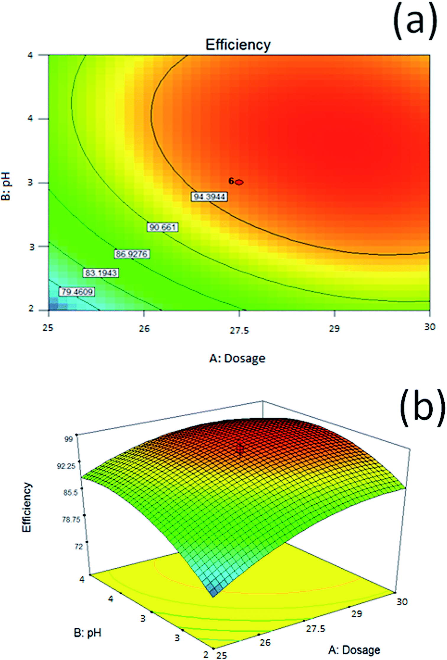
Fig. 10 demonstrates graphical 3D contour plots and model surfaces. The predicted quadratic model generated 3D response surface plots, which were used to study the relationship between reaction parameters and responses. In addition, the 3D response surface plots can be used to determine the optimum level of each parameter for the demulsification of M–RGO6. Fig. 10a and b respectively show the effect of the pH value and dosage of M–RGO6 on demulsification. The pH and dosage parameters exerted a positive effect on demulsification efficiency, which influenced the dosage concentration in the oil emulsion. As indicated in Fig. 10b, increasing the dosage of M–RGO6 from 25 g L−1 to 29 g L−1 increased the demulsification efficiency from 88.88% to 95.63%. Although increasing the M–RGO concentration from 25 g L−1 to 29 g L−1 increases the demulsification efficiency, after reaching the maximum point, additional dosage would slightly reduce the demulsification efficiency. Demulsification optimization was designed in an acidic condition, which ranges from pH 2 to 4. The effect of pH on demulsification efficiency is shown in Fig. 10. The maximum demulsification efficiency of M–RGO was achieved at pH 4. This result is attributed to the ionization of acids, which influenced the demulsifier and changed the physical properties of the interfacial film in oil emulsion. According to Table 7, brine concentration had little contribution to demulsification efficiency. Thus, this parameter is not included in the contour plot. An optimum dosage of M–RGO and pH exists to achieve maximum demulsification efficiency. The red region in the contour plot and 3D surface shown in Fig. 10 indicates the optimum conditions for demulsification efficiency. The response surface shows the optimal combination of parameters to obtain the highest demulsification efficiency when the dosage is equal to 29 g L−1 at pH 4.
 |
| | Fig. 10 Response surface of demulsification efficiency versus pH value and dosage of M–RGO6 (a) contour plot and (b) 3D surface. | |
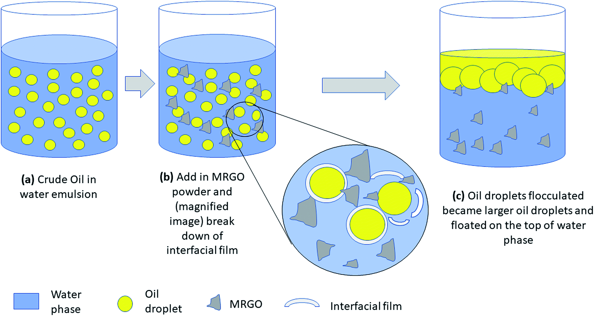
The plausible demulsification mechanism was speculated. Crude oil and water are two immiscible liquids that cannot disperse well in each other in the absence of a surfactant. In this study, Tween 60 was used to form crude oil in water emulsion by reducing the tension between the oil phase and the water phase. Tween 60 is composed of a hydrophilic head and a hydrophobic tail oriented toward the water and oil phase, respectively. Thus, a stable crude oil in water is formed. After M–RGO powder was added to crude oil in water emulsion, it entered the oil–water interface upon shaking. The increase in the dosage caused the interaction of M–RGO nanocomposites and crude O/W emulsion molecules to reach equilibrium at the interface. Subsequently, the surfactant molecules were drain away with continuously shaking. Thus, the strength of the interfacial film decreased and start breaking down. Destroying the interfacial film at the oil water interface is the key to demulsify the stable emulsion.23 Later, small oil droplets start flocculated and coalesced into larger oil droplets and floated on the top of water. Schematic of the plausible demulsification mechanism was sketched and presented in Fig. 11.
 |
| | Fig. 11 Schematic diagram illustrated the demulsification process when M–RGO was added in the oil in water emulsion. | |
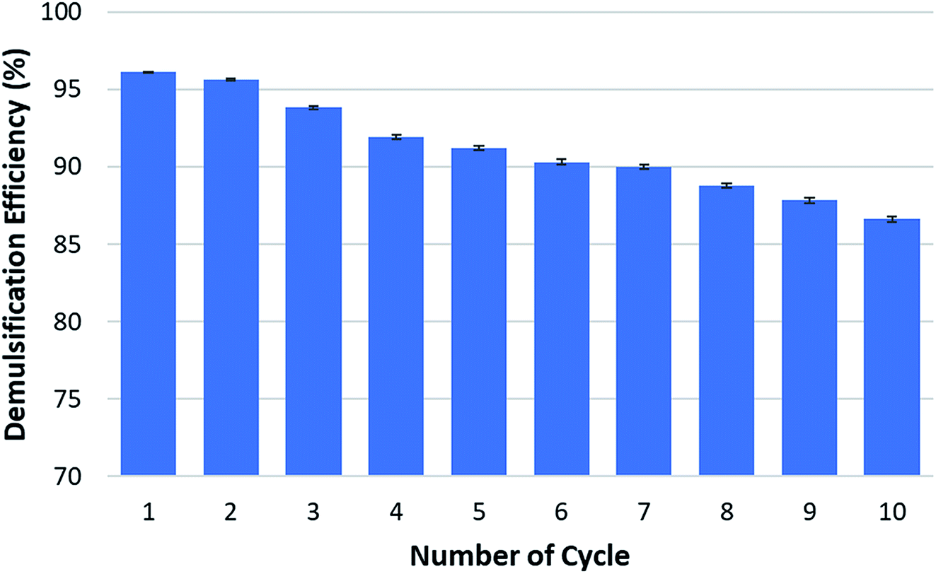
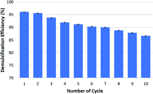
Recycle test had been conducted in order to know the recyclability of this magnetic demulsifier and the results were presented in Fig. 12. From the optimization test, highest demulsification efficiency found at pH 4. Therefore, the recycle test was conducted at pH 4 with dosage of 29 g L−1. As can be seen from Fig. 12, demulsification efficiency of M–RGO nanocomposites are gradually decreased. However, at the 7th cycle, the demulsification efficiency start to drop to a value which is less than 90% i.e. 88.78%. At the 9th cycle, it dropped again to 86.6%. This could be attributed to the small amount of oil droplets tagged on the surface of M–RGO nanocomposites. These small amount of oil droplets could not be easily removed by ethanol during the washing process, especially after several cycles, thus causing a gradual decrease in demulsification efficiency during recycling. This phenomenon was in agreement with the finding proposed by Liu and his co-workers.27 Overall, the M–RGO nanocomposites still showed a reasonable demulsification performance for crude O/W emulsion in this study after nine cycles. The recyclability of M–RGO nanocomposites as demulsifier consequently reduced the cost in practical applications. At the same time, this demulsifier also consider eco-friendly because it does not contribute to recontamination of environment.
 |
| | Fig. 12 Demulsification efficiencies of M–RGO nanocomposites in crude O/W emulsion for multiple cycle tests. | |
4. Conclusions
M–RGO nanocomposites were synthesized through in situ chemical synthesis. The characterization analysis proved the successful synthesis of M–RGO nanocomposites. M–RGO nanocomposites with different stirring times, namely, M–RGO3 (3 h) and M–RGO6 (6 h), were synthesized. From the characterization results, M–RGO6 was selected to perform the demulsification test on O/W emulsion. Long stirring time resulted in the stacking of additional Fe3O4 nanoparticles on the rGO surface. M–RGO6 was chosen for the demulsification test due to its high magnetization and low integral intensity ratio; moreover, the distribution of Fe3O4 nanoparticles on rGO sheets is even and the fully reduction of GO to rGO. RSM based on CCD was used to investigate the effect of dosage, pH value, and brine concentration on demulsification efficiency. ANOVA analysis showed that the coefficient of variations and R2 of responses were acceptable. Dosage and pH value were the two main parameters in the demulsification process. However, brine concentration, which only had a slight effect on demulsification, can be ignored. The optimum demulsification efficiency of 96% was achieved in an acidic condition of pH 4 with an M–RGO dosage of 29 g L−1. From the recycle test, results shown that this M–RGO nanocomposites possess good recyclability.
Conflicts of interest
There are no conflicts to declare.
Acknowledgements
The authors would like to acknowledge Yayasan Universiti Teknologi PETRONAS (YUTP-FRG 0153AA-E40) from Universiti Teknologi PETRONAS for financial support.
References
- J. Lodungi, D. Alfred, A. Khirulthzam, F. Adnan and S. Tellichandran, Int. J. Waste Resour., 2016, 7, 2 Search PubMed.
- D. Robinson, Filtr. Sep., 2010, 47, 14–18 CrossRef CAS.
- T. F. Tadros, Emulsion formation and stability, John Wiley & Sons, 2013 Search PubMed.
- J. Floury, A. Desrumaux and J. Lardières, Innovative Food Sci. Emerging Technol., 2000, 1, 127–134 CrossRef CAS.
- S. Ma, Y. Wang, K. Jiang and X. Han, Nano Res., 2015, 8, 2603–2610 CrossRef CAS.
- P. Hajivand and A. Vaziri, Braz. J. Chem. Eng., 2015, 32, 107–118 CrossRef CAS.
- S. A. Issaka, A. H. Nour and R. M. Yunus, J. Pet. Environ. Biotechnol., 2015, 6, 1 CAS.
- H. Xu, W. Jia, S. Ren and J. Wang, Chem. Eng. J., 2018, 337, 10–18 CrossRef CAS.
- D. Chen, Q. Tang, X. Li, X. Zhou, J. Zang, W.-Q. Xue, J.-Y. Xiang and C.-Q. Guo, Int. J. Nanomed., 2012, 7, 4973 CrossRef CAS PubMed.
- D. Li, M. Hua, K. Fang and R. Liang, Anal. Methods, 2017, 9, 3099–3104 RSC.
- Y.-L. Zhang, Q.-D. Chen, Z. Jin, E. Kim and H.-B. Sun, Nanoscale, 2012, 4, 4858–4869 RSC.
- S. Ma, Y. Wang, X. Wang, Q. Li, S. Tong and X. Han, ChemistrySelect, 2016, 1, 4742–4746 CrossRef CAS.
- H. Sun, L. Cao and L. Lu, Nano Res., 2011, 4, 550–562 CrossRef CAS.
- P. Teo, H. Lim, N. Huang, C. H. Chia and I. Harrison, Ceram. Int., 2012, 38, 6411–6416 CrossRef CAS.
- Z. Li, L. Wei, M. Gao and H. Lei, Adv. Mater., 2005, 17, 1001–1005 CrossRef CAS.
- G. Ren, L. Yang, Z. Zhang, B. Zhong, X. Yang and X. Wang, J. Alloys Compd., 2017, 710, 875–879 CrossRef CAS.
- A. Tayyebi and M. Outokesh, RSC Adv., 2016, 6, 13898–13913 RSC.
- Y. Yoon, W. K. Park, T.-M. Hwang, D. H. Yoon, W. S. Yang and J.-W. Kang, J. Hazard. Mater., 2016, 304, 196–204 CrossRef CAS PubMed.
- M. F. Hossain and J. Y. Park, PLoS One, 2017, 12, e0173553 CrossRef PubMed.
- Y. Qin, M. Long, B. Tan and B. Zhou, Nano-Micro Lett., 2014, 6, 125–135 CrossRef CAS.
- I. Calizo, A. Balandin, W. Bao, F. Miao and C. Lau, Nano Lett., 2007, 7, 2645–2649 CrossRef CAS PubMed.
- O. Akhavan, E. Ghaderi, E. Hashemi and R. Rahighi, Nanoscale, 2014, 6, 14810–14819 RSC.
- J. Liu, X. Li, W. Jia, Z. Li, Y. Zhao and S. Ren, Energy Fuels, 2015, 29, 4644–4653 CrossRef CAS.
- P. Hu, L. Kang, T. Chang, F. Yang, H. Wang, Y. Zhang, J. Yang, K.-S. Wang, J. Du and Z. Yang, J. Alloys Compd., 2017, 728, 88–92 CrossRef CAS.
- A. Hafizi, A. Ahmadpour, M. Heravi, F. Bamoharram and M. Khosroshahi, Chin. J. Catal., 2012, 33, 494–501 CrossRef CAS.
- K. Jumbri, M. F. A.-H. Rozy, S. E. Ashari, R. Mohamad, M. Basri and H. R. F. Masoumi, PLoS One, 2015, 10, e0144664 CrossRef PubMed.
- J. Liu, H. Wang, X. Li, W. Jia, Y. Zhao and S. Ren, Fuel, 2017, 189, 79–87 CrossRef CAS.
|
| This journal is © The Royal Society of Chemistry 2019 |
Click here to see how this site uses Cookies. View our privacy policy here. 
 Open Access Article
 This Open Access Article is licensed under a Creative Commons Attribution-Non Commercial 3.0 Unported Licence
 *bc,
Xin Hui Yaubc,
Wei Wen Liu
*bc,
Xin Hui Yaubc,
Wei Wen Liu