 Open Access Article
A three-dimensional metal–organic framework for a guest-free ultra-low dielectric material†
W. Xu‡
b,
S. S. Yu‡a,
H. Zhang‡a and
H. B. Duan *ac
*ac
aSchool of Environmental Science, Nanjing Xiaozhuang University, Nanjing, 211171, P. R. China. E-mail: duanhaibao4660@163.com
bDepartment of Chemistry, Huangshan University, Huangshan 245041, P. R. China
cDepartment of Chemistry and Biochemistry, University of California, Los Angeles, California 90095-1569, USA
First published on 23rd May 2019
Abstract
A three-dimensional metal–organic framework compound [NH2(CH3)2]2[Zn3(bpdc)4]·3DMF (1) shows two step dielectric relaxation and its guest-free framework (1′) possesses an ultra-low κ value of 1.80 (at 100 kHz, it is the lowest value for MOFs reported to date) over a wide temperature range and high thermal stability.
The design and synthesis of low dielectric constant (low-κ) materials has been a subject of interest in terms of their potential for use in high performance electronic devices. Materials with extremely low-dielectric constants have been targeted as interlayer dielectrics (ILD) because they decrease the cross-talk noise, propagation delay, and power dissipation in most electronic components. 1–5 Indeed, the search for new low-κ materials replacing silicon dioxide (SiO2) as an ILD has always been dictated by industrial needs, resulting in a strong connection between fundamental research and technology.6 Many materials have been proposed and studied as potential candidates; two major classes are dense organic polymers and porous inorganic-based materials. Some dense organic polymers could have κ below 2.2, but they suffer from concerns of low thermal stability and thermal conductivity. For porous inorganic-based low-κ materials, sol–gel silica, doped oxides and mesoporous silica have been extensively studied.7 but its low mechanical strength, wide pore size distribution, and hydrophilicity have been cited as concerns.
As air or vacuums have the lowest dielectric constant (κ = 1.01), the partial replacement of solid network with air or a vacuum appears to be the more intuitive and direct option to the development of new low-κ ILD materials. Thus, as per the International Technology Roadmap for Semiconductors (ITRS), robust porous materials and air gap structures will become target low-κ materials in the near future.8 Metal–organic frameworks (MOFs) with a well-defined monodisperse porosity, large surface area, ultra-low densities, high stability and easy tunability of the surface and structural properties have potential for meet the demands for use as stable low-κ materials.9 MOFs have been extensively studied over the past decade for their applications in gas storage, sensors, chemical separation, catalysis, drug delivery and biomedical imaging.10–12 However, their electrical properties and applications in microelectronics remain under researched.13 MOFs should be stiffer and harder than other low-density amorphous inorganic or organic polymers because of their ordered framework and rigid organic linkers. With tunable structural properties, high porosity, and thermal/mechanical stability, MOFs represent an ideal replacement as an ILD material. Hermann and coworkers presented a brief theoretical model for using MOFs as low-κ materials in microelectronics applications.14 However, these theoretical calculations did not take into account the orientational and ionic contributions to the molecular polarizability, which drastically contribute to the dielectric constant. These theoretical results encouraged us to search for new MOFs materials with experimentally ultra-low κ values.
In this work, we report on the preparation of a MOFs, [NH2(CH3)2]2[Zn3(bpdc)4]·3DMF (1) (H2bpdc = 4,4′-biphenyldicarboxylic acid), which have 3D frameworks with high thermal stability (Fig. S1†) and a ultra-low κ values of its guest-free sample 1′. The 1′ possesses a very low κ values of 1.80 (at 100 kHz) and high thermal stability at temperatures up to 360 °C (Fig. S2†), making it a potential candidate for use as an ILD. To the best of our knowledge, to date, the κ values of 1′ is the lowest value for MOFs reported. Furthermore, compound 1 shows dielectric relaxation and anomalies in the temperature range of 35–140 °C. Dielectric relaxation and anomalies of 1 is related to reorientation of the dipole moment of surface absorbed water and guest DMF molecules, respectively.
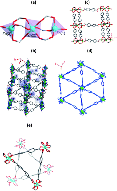
The compound 1 was obtained from the solvothermal reaction of Zn(NO3)2·6H2O, H2bpdc and [NH2(CH3)2]Cl in DMF. X-ray crystallographic analysis reveals that it crystallizes in the space group Pna21.§ The asymmetric unit contains of three crystallographically distinct Zn2+ ions, four deprotonated bpdc2− ligands, two [NH2(CH3)2]+ ions and three free DMF molecules. Three crystallographically independent Zn2+ ions have two coordination modes (Fig. 1a). The Zn(1) and Zn(3) adopts a four-coordinated and formed slightly distorted tetrahedral geometry, and the Zn(2) adopts a six-coordinated geometry. O13 and O16 atoms originated from monodentate coordination of the bpdc2− ligands and the other oxygen atoms are coordinated by μ2-modes bpdc2− ligands to Zn2+ ions. The shortest and longest Zn–O distance is 1.881(10) and 2.088(9) Å, respectively. Each Zn(2) atom is connected Zn(1) atom and Zn(3) atom by three bridged bidentate bpdc2− ligands to form trinuclear building blocks. As shown in Fig. 1b, trinuclear building blocks are further linked together by bpdc2− ligands make up the 3D anionic framework with two different channels, and the channels is occupied by [NH2(CH3)2]+ ions and disordered DMF guest molecules. Parallel to the ac plane, the monodentate bpdc2− ligands bridge trinuclear building blocks to afford layers stacking, and the layers are pillared by bidentate bpdc2− ligands to give rise to a regular 3D network (Fig. 1c), and channel dimensions is about 13 × 18 Å along the b-axis direction. The triangle cage was formed along the c-axis direction with small channel (Fig. 1d). Overall, two individual triangle cage are independent interpenetrated to form the entire framework of 1 (Fig. 1e). It should be noted that although the framework of 1 is interpenetration networks, it is still highly porous. After the removal of solvent molecules in the channels, the accessible volume of 1 is 40.2%.
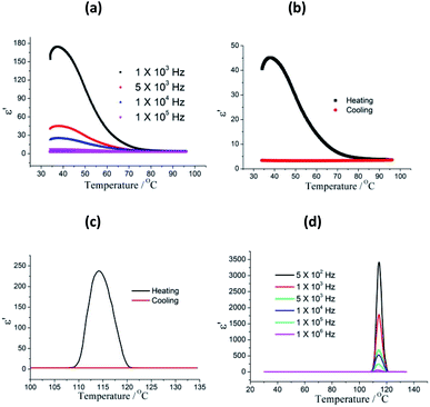
The temperature dependent dielectric properties were investigated in the temperature rang of 30–135 °C, and two-step dielectric relaxation were observed. As show in Fig. 2a, it is clear that compound 1 shows the first step dielectric relaxation in the temperature range of 30–80 °C. When 1 was heated from 30 to 37 °C, the dielectric constant progressive increased and reaches a maximum of 174.4 at 103 Hz. Further increase in temperature results in the dielectric constant of 1 slowly decreasing and dielectric peak disappears. The first step dielectric relaxation is due to the relaxation of absorbed water molecules in the sample surface. The dielectric relaxation signal was not observed in the cooling process (from 95 °C to 30 °C) for losing surface water (Fig. 2b). The κ value is directly related to the polarization phenomena. The higher the polarization, the greater the increase in κ value will be. Usually, the MOF materials with low κ value feature the reorientational motions of polar guest molecules being restricted at low temperature or frameworks solvent-free. However, for 1, the thermally assisted dynamical dipole motion due to polar DMF molecules is appeared. The guest molecules get enough excitation thermal energy to be able to obey the change under the external electric field more easily in the high temperature regime, and the reorientational dynamics of guest molecules is activated above 105 °C. This in return enhances their contribution to the polarization leading to an sharp increase of dielectric permittivity value. At f = 105 Hz, the dielectric constant reaches a maximum of 237, and then sharply decreased when the temperature increased. In the following cooling process, a very low κ value was observed and no dielectric relaxation was occurred (Fig. 2c). The second step dielectric relaxation at different frequency are shown in Fig. 2d, which can be ascribed to the guest polar DMF reorientational motions. In addition, the dielectric loss values shows similar features in the selected frequency range (Fig. S3†).
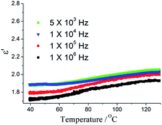
Removing polar guest molecules from the framework may be decreases the polarization and the possibility of any type of hydrogen bonding or ionic interactions between the framework and guest molecular, hence, the κ value will also decreases. The guest-free sample 1′ were obtained by simply heating method. The PXRD patterns of the 1 match well with the 1′ (Fig. S4†), thus demonstrating the phase were unaltered. The dielectric properties of guest-free sample 1′ were investigated. As shown in Fig. 3, after removing the polar DMF molecules, a very low κ value of 1.78 at 100 kHz at 40 °C with a low dielectric loss (0.005) was observed (Fig. S5†). It is very interesting as the temperature increase from 40 to 130 °C, κ value increases very slowly. κ value is 1.99 at 130 °C. With the ac electric field frequency increasing, the κ value slightly decrease (Fig. 3a). It is noteworthy that, to date, dielectric investigations of MOFs have received relatively little attention, although a few exciting examples have been reported. Only a limited number of MOFs have been reported to possess ultra-low κ value.15,16 The ultra-low κ values for a few MOFs are shown in Table S2.†17 To the best of our knowledge, the κ values of 1′ is the lowest value for MOFs reported. From the published paper and our results, to obtained the ultra-low κ MOFs, ligands should have high symmetry and small polarity and polar guest molecular should be avoid. Furthermore, some small counter ions could be decrease κ values. As the vacuum has the lowest dielectric constant, thus, κ values can be reduced significantly by increasing porosity of MOFs. High thermal stability and MOFs thin-film growth are required for the practical applications of ultra-low κ MOFs in microelectronics. ZIF-8 films with κ value of 2.4 were deposited on silicon wafers and characterized in order to assess their potential as future insulators (low-κ dielectrics) in microelectronics.18 We recently reported a hydrogen bonding MOFs [Zn(H2EIDA)2(H2O)]·2DMF, which exhibited low-κ behaviour, but its thermal stability was not perfect.
Conclusions
In conclusion, we have presented a 3D MOFs [NH2(CH3)2]2[Zn3(bpdc)4]·3DMF (1) and its guest-free framework (1′). 1 possesses two types of cavities, which are occupied by counter ions and the polar solvents DMF, and shows two-step dielectric relaxations which is related to reorientation of the dipole moment of surface absorbed water and guest DMF molecules. Two step relaxation were not observed in guest-free framework 1′. 1′ shows quite low κ value (to the best of our knowledge, the κ values of 1′ is the lowest value for MOFs reported to date) and high thermal stability. The ultra-low κ value exhibits no significant change over a wide temperature range (40–130 °C). The ultra-low dielectric constant of 1′ can be attributed to the highly porous and small counter ions in the channels. The foregoing results discussed in this work provide an effective path towards achieving remarkable new applications for dielectric MOFs in the future.Conflicts of interest
There are no conflicts to declare.Acknowledgements
The authors thanks Natural Science Foundation of JiangSu Province and Natural Science Training Foundation of Nanjing Xiaozhuang University for their financial support (grant No: BK20171125 and 2016NXY12).Notes and references
- W. Volksen, R. D. Miller and G. Dubois, Chem. Rev., 2010, 110, 56 CrossRef CAS.
- M. D. Allendorf and V. Stavila, CrystEngComm, 2015, 17, 229 RSC.
- P. Ramaswamy, N. E. Wong and G. K. H. Shimizu, Chem. Soc. Rev., 2014, 43, 5913 RSC.
- R. Ameloot, M. Aubrey, B. M. Wiers, A. P. GÖmora-Figueroa, S. N. Patel, N. P. Balsara and J. R. Long, Chem.–Eur. J., 2013, 19, 5533 CrossRef CAS PubMed.
- H. Kitagawa, Nat. Chem., 2009, 1, 689 CrossRef CAS PubMed.
- (a) J. Martin, J. P. Godschalx, M. E. Mills, E. O. Shaffer II and P. H. Townsend, Adv. Mater., 2000, 12, 1769 CrossRef; (b) W. Volksen, R. D. Miller and G. Dubois, Chem. Rev., 2010, 110, 56 CrossRef CAS PubMed.
- (a) R. D. Miller, Science, 1999, 286, 421 CrossRef CAS; (b) S. Seraji, Y. Wu, M. Forbess, S. J. Limmer, T. Chou and G. Cao, Adv. Mater., 2000, 12, 1695 CrossRef CAS; (c) Y. F. Lu, H. Y. Fan, N. Doke, D. A. Loy, R. A. Assink, D. A. LaVan, C. J. Brinker and J. Am, J. Am. Chem. Soc., 2000, 122, 5258 CrossRef CAS; (d) S. Baskaran, J. Liu, K. Domansky, N. Kohler, X. L. Li, C. Coyle, G. E. Fryxell, S. Thevthasan and R. E. Williford, Adv. Mater., 2000, 12, 291 CrossRef CAS.
- The International Technology Roadmap For Semiconductors (ITRS), 2011 edition.
- (a) H. Li, M. Eddaoudi, M. O'Keeffe and O. M. Yaghi, Nature, 1999, 402, 276 CrossRef CAS; (b) G. Ferey, Chem. Soc. Rev., 2008, 37, 191 RSC; (c) S. Kitagawa, R. Kitaura and S. Noro, Angew. Chem., Int. Ed., 2004, 43, 2334 CrossRef CAS PubMed.
- S. S. Han, J. L. Mendoza-Cortes and W. A. Goddard, Chem. Soc. Rev., 2009, 38, 1460 RSC.
- (a) R. E. Morris and P. S. Wheatley, Angew. Chem., Int. Ed., 2008, 47, 4966 CrossRef CAS; (b) T. Borjigin, F. Sun, J. Zhang, K. Cai, H. Ren and G. Zhu, Chem. Commun., 2012, 48, 7613 RSC; (c) D. Farrusseng, S. Aguado and C. Pinel, Angew. Chem., Int. Ed., 2009, 48, 7502 CrossRef CAS PubMed; (d) C. Y. Sun, C. Qin, C. G. Wang, Z. M. Su, S. Wang, X. L. Wang, G. S. Yang, K. Z. Shao, Y. Q. Lan and E. B. Wang, J. Am. Chem. Soc., 2011, 23, 5629 CAS.
- J. Lee, O. K. Farha, J. Roberts, K. A. Scheidt, S. T. Nguyen and J. T. Hupp, Chem. Soc. Rev., 2009, 38, 1450 RSC.
- S. Eslava, L. Zhang, S. Esconjauregui, J. Yang, K. Vanstreels, M. R. Baklanov and E. Saiz, Chem. Mater., 2013, 25, 27 CrossRef CAS.
- K. Zagorodniy, G. Seifert and H. Hermann, Appl. Phys. Lett., 2010, 97, 251905 CrossRef.
- (a) W. J. Li, J. Liu, Z. H. Sun, T. F. Liu, J. Lu, S. Y. Gao, C. He, R. Cao and J. H. Luo, Nat. Commun., 2016, 7, 11830 CrossRef CAS; (b) M. Usman, C. H. Lee, D. S. Hung, S. F. Lee, C. C. Wang, T. T. Luo, L. Zhao, M. K. Wu and K. L. Lu, J. Mater. Chem. C, 2014, 2, 3762 RSC; (c) S. Eslava, L. Zhang, S. Esconjauregui, J. Yang, K. Vanstreels, M. R. Baklanov and E. Saiz, Chem. Mater., 2013, 25, 27 CrossRef CAS.
- (a) S. Mendiratta, M. Usman, T. T. Luo, B. C. Chang, S. F. Lee, Y. C. Lin and K. L. Lu, Cryst. Growth Des., 2014, 14, 1572 CrossRef CAS; (b) S. Mendiratta, M. Usman, T. T. Luo, S. F. Lee, Y. C. Lin and K. L. Lu, CrystEngComm, 2014, 16, 6309 RSC; (c) S. S. Yu, G. J. Yuan and H. B. Duan, RSC Adv., 2015, 5, 45213–45216 RSC; (d) F. Wang, C. Y. Ni, Q. Liu, F. L. Li, J. Shi, H. X. Lia and J. P. Lang, Chem. Commun., 2013, 49, 9248 RSC; (e) P. Yang, X. He, M. X. Li, Q. Ye, J. Z. Ge, Z. X. Wang, S. R. Zhu, M. Shao and H. L. Cai, J. Mater. Chem., 2012, 22, 2398 RSC.
- (a) M. Usman, S. Mendiratta and K. L. Lu, ChemElectroChem, 2015, 2, 786 CrossRef CAS; (b) P. C. Guo, Z. Chu, X. M. Ren, W. H. Ning and W. Jin, Dalton Trans., 2013, 42, 6603 RSC; (c) V. DiNoto, A. B. Boeer, S. Lavina, C. A. Muryn, M. Bauer, G. A. Timco, E. Negro, M. Rancan, R. E. P. Winpenny and S. Gross, Adv. Funct. Mater., 2009, 19, 3226 CrossRef CAS; (d) L. Z. Chen, J. Zou, Y. M. Gao, S. Wan and M. N. Huang, J. Coord. Chem., 2011, 64, 715 CrossRef CAS; (e) P. C. Guo, T. Y. Chen, X. M. Ren, W. H. Ning and W. Jin, New J. Chem., 2014, 38, 2254 RSC.
- S. Eslava, L. Zhang, S. Esconjauregui, J. Yang, K. Vanstreels, M. R. Baklanov and E. Saiz, Chem. Mater., 2013, 25, 27 CrossRef CAS.
Footnotes |
| † Electronic supplementary information (ESI) available: Experimental details, additional figures, powder XRD, TG and dielectric loss curves. CCDC 1884532. For ESI and crystallographic data in CIF or other electronic format see DOI: 10.1039/c9ra03032h |
| ‡ These authors contributed equally. |
| § Crystal data for compound 1, space group Pna21, a = 24.7046(12) Å, b = 14.5230(9) Å, c = 22.3879(12) Å, α = β = γ = 90.00°, V = 8032.4(8) Å3, Z = 4, Dc = 1.033 g cm−3, Mu = 0.939 mm (see ESI). |
| This journal is © The Royal Society of Chemistry 2019 |


