
 Open Access Article
 This Open Access Article is licensed under a Creative Commons Attribution-Non Commercial 3.0 Unported Licence
Fabrication of PP hollow fiber membrane via TIPS using environmentally friendly diluents and its CO2 degassing performance†
Su-Ying Yana,
Yu-Jie Wangab,
Heng Maob and
Zhi-Ping Zhao *a
*a
aSchool of Chemistry and Chemical Engineering, Beijing Institute of Technology, Beijing 102488, China. E-mail: zhaozp@bit.edu.cn; Fax: +86-10-68911032; Tel: +86-10-68911032
bEnvironmental Protection Research Institute, Beijing Research Institute of Chemical Industry, SINOPEC, Beijing 100013, China
First published on 18th June 2019
Abstract
CO2 removal is an essential water purification process in many fields, such as petrochemical production and thermal power generation. It is challenging to remove low concentrations of CO2 from RO effluent water. The core component of the membrane degassing technique is a high-performance hydrophobic microporous membrane. Polypropylene (PP) membranes were prepared with environmentally friendly binary diluents via thermally induced phase separation. Firstly, the effects of PP concentration on the phase diagram, flat sheet membrane structure and mechanical properties were studied to optimize the PP content for a hollow fiber membrane (HFM). The PP HFM showed a sponge-like cross-sectional structure without any dense skin layer, a large loading force and breaking elongation, and a narrow pore size distribution with a mean pore size of 0.16 μm. The as-fabricated PP HFM module was applied for CO2 removal from RO effluent water from a petrochemical plant. A higher water temperature and vacuum degree facilitated CO2 removal. Increasing the effective membrane length enhanced degassing efficiency. Increasing the water flow rate increased CO2 degassing flux, but simultaneously decreased degassing efficiency. When the water flow rate increased from 20 mL min−1 to 63 mL min−1, although the effective membrane length increased from 3 m to 4.8 m for the best degassing efficiency of 88%, the amount of treated water increased by 3.15 times. The declined CO2 concentration in the outlet water was 1.6 mg L−1.
1. Introduction
CO2 removal from water is an essential water purification process in many fields: for example, petrochemical production, thermal power generation and fabrication of microelectronic devices.1 Typically, boiler water systems in petrochemical plants require large amounts of high-quality water.2 CO2 in the water needs to be removed before the ion exchange bed, as it adds an excessive load to the ion exchange bed, resulting in frequent chemical regeneration.3 In reverse osmosis (RO) and electrodeionization (EDI) systems, the CO2 content must also be controlled.4 In an RO system, the removal CO2 can be achieved by adding an alkali such as sodium hydroxide. However, this may lead to more chemical pollutants in RO concentrated water.5 Traditional industrial degassing technologies, including packed towers, spray towers and bubble columns, have many shortcomings such as large floor areas and operational problems like entrainment, flooding, and emulsion foaming.6A hollow fiber membrane (HFM) contactor, as a promising method for CO2 absorption and desorption, was first introduced in 1985 by Qi and Cussler.7 Within this technique, a liquid phase and a gas phase can make non-dispersive contact via a microporous membrane that functions as the interface between liquid and gas.8,9 Hence, liquid flows inside HFMs, while outside the HFMs, stripping gas or a vacuum were employed. The dissolved gas leaves the liquid phase, penetrates into the membrane pores and then enters the gas phase.10
Membrane technology has unique advantages, including large interfacial area, independent control of the fluid flow rates, small size, modularity and ease of scaling up or down, as well as operational flexibility.11 Despite the fact that membrane absorption and membrane degassing are two applications for membrane contactors, most research has emphasized CO2 absorption using gas–liquid membrane contactors. Indeed, investigations into CO2 degassing through membrane contactors are very rare in the current literature. A few studies reported CO2 degassing using different HFM modules. Mansourizadeh and Ismail12 employed porous polyvinylidene fluoride (PVDF) HFMs to evaluate CO2 stripping performance from water. The results indicated that the liquid phase temperature, gas–liquid contact area and contact time are the key parameters for enhancing CO2 stripping efficiency. Rahbari-Sisakht et al.13 used a polysulfone HFM contactor for CO2 stripping from water. The results showed that the gas velocity had a minor effect on the CO2 desorption flux. Khaisri et al.14 employed polytetrafluoroethylene (PTFE) hollow fiber membranes to investigate the CO2 desorption performance from CO2-loaded monoethanolamine (MEA) solutions. The high membrane porosity showed superior desorption performance, but the long-term performance underwent severe degradation due to membrane wetting. Under high temperature conditions, Koonaphapdeelert et al.15 used costly ceramic hollow fiber membrane contactors for CO2 stripping from MEA solution.
Since membrane fouling and wetting will reduce the degassing efficiency, there are several requirements for ideal membrane materials:16 (1) outstanding chemical and thermal stability; (2) excellent hydrophobicity; (3) high mechanical strength; (4) feasibility for commercial application. Pore size and pore size distribution also have large effects on degassing performance.
Degassing membranes are mainly produced from hydrophobic polymers, particularly polypropylene (PP), PTFE, polyethylene, and poly(vinylidene fluoride).17 PP is commonly used for membrane preparation because of its excellent properties. PP membranes are usually produced by stretching or thermal methods, on account of their insolubility in common solvents.18 In fact, several papers have reported the preparation of hydrophobic microporous PP HFM via a thermally induced phase separation (TIPS) process, and membrane structure and morphology were optimized by adjusting various preparation conditions. Lloyd et al. studied the solid–liquid (S–L) and liquid–liquid (L–L) phase separation of porous PP membranes prepared via TIPS.19 The parameters of diluent type and its content,20 polymer concentration21 etc. could influence the compatibility between polymer and diluents, and lead to different phase separation types, which would further determine the membrane morphology, pore size and membrane performance.
Nowadays, most PP membranes prepared via TIPS use various single and binary diluents, such as diphenyl ether (DPE),22 soybean oil and dibutyl phthalate (DBP),23 etc. Binary diluents can greatly influence the compatibility between polymer and diluents, and can significantly change the phase separation behavior and membrane morphology. However, some diluents mentioned above may be toxic and harmful to human health. In previous studies, we chose castor oil (CO) and soybean oil (SO) as environmentally friendly binary diluents and optimized the appropriate binary diluents mass ratio.
As mentioned above, the studies of membrane degassing reported so far focus on absorption of high-concentration CO2 solutions. It is challenging to remove a low concentration of CO2 from RO effluent water. Herein, microporous PP HFM was prepared via TIPS for CO2 degassing from RO effluent water from a petrochemical enterprise. Firstly, the effects of PP concentration on the phase diagram, membrane structure and mechanical properties were studied during preparation of PP flat-sheet membranes in order to optimize the PP content for HFM. PP HFM was then fabricated via TIPS with the optimal casting solution composition. Furthermore, the CO2 degassing performance of the PP membrane module was studied with RO effluent water. The effects of feed flow rate, vacuum degree, temperature, and effective membrane length on CO2 degassing performance were investigated.
2. Experimental and materials
2.1. Materials
SO and CO were bought from COFCO, Co. China. The PP was provided by Sinopec, F280M, MI = 2.8 g/10 min (190 °C, 2.16 kg), Mw = 400![[thin space (1/6-em)]](https://www.rsc.org/images/entities/char_2009.gif) 000, Mw/Mn = 7.7. Sodium hydroxide was purchased from Beijing Chemical Works, China. Phenolphthalein and potassium hydrogen phthalate were purchased from Shanghai Macklin Biochemical, China. Ethanol and n-hexane of analytical grade were purchased from China Sinopharm Chemical Reagent Co., China.
000, Mw/Mn = 7.7. Sodium hydroxide was purchased from Beijing Chemical Works, China. Phenolphthalein and potassium hydrogen phthalate were purchased from Shanghai Macklin Biochemical, China. Ethanol and n-hexane of analytical grade were purchased from China Sinopharm Chemical Reagent Co., China.
2.2. Phase diagram and membrane preparation
Homogeneous PP-diluents solid samples were prepared by a previously described method.24 The sample preparation conditions are listed in detail in Table S1 (in ESI†). A small piece of solid sample was sandwiched between two glass coverslips, sealed around with vacuum grease to limit evaporation of diluents. The sample was heated on a hot stage (Linkam THMS 600, UK) up to 200 °C at a heating rate of 50 °C min−1, maintained for 5 min to assure homogeneity, then cooled to about 50 °C at a cooling rate of 10 °C min−1. The cloud point temperature of the sample was determined visually by noting the appearance of turbidity under a phase contrast mode microscope (BX51M, Olympus, JAPAN). The crystallization temperature of the sample was determined visually by noting the appearance of nucleation under a polarized microscope (BX51M, Olympus, JAPAN). The temperature values were obtained based on an average of three parallel measurements.Detail of the preparation of PP flat-sheet membranes and PP HFMs via TIPS can be found in ESI.†
2.3. Membrane characterization
2.4. CO2 degassing experiment
A total of 10 PP HFMs were packed randomly in a polymethyl methacrylate tube with the two ends sealed by epoxy resin for fabrication into a membrane module. The specifications of the membrane module are given in Table 1.| Properties | Values |
|---|---|
| Length of module/cm | 70 |
| Effective length/cm | 60 |
| Module I.D/O.D/cm | 4.3/5.0 |
| Fiber I.D/O.D/μm | 1161/1822 |
| No. of fibers | 10 |
The RO effluent water with dissolved CO2 flowed through the lumen side of the membrane module and a vacuum was introduced on the shell side. This effluent water was collected from the RO system at the Luoyang Petrochemical Engineering Corporation Ltd/SINOPEC. The water temperature was kept constant with a water bath and the flow rate was controlled by a peristaltic pump. The vacuum degree was adjusted by a vacuum regulating valve. A flow diagram of the experimental setup is shown in detail in Fig. S1 (in ESI†). The CO2 concentrations of the entry and outlet water of the module were measured by the chemical titration method.13
The CO2 degassing efficiency was calculated as:
 | (1) |
The CO2 degassing flux was calculated as:
 | (2) |
3. Results and discussion
3.1. Phase diagram
The type of phase separation is directly determined from the phase diagram.20,25 Fig. 1 is the phase diagram of the PP/binary diluents system on various PP concentrations with 16 wt% CO in the diluents. It presents cloud point and dynamic crystallization temperatures. The cloud point decreased greatly with an increase in PP concentration. The cloud point reached its highest value of 176 °C at 10 wt% PP, and dropped to 136 °C at 40 wt% PP. The phenomena can be analysed in terms of the interaction between PP and the binary diluents. The Flory–Huggins interaction parameter (χ) is typically used to interpret the interaction between the polymer and the diluent. When the PP concentration was increased, the χ became smaller, which resulted in the decrease in cloud point.20 This indicated that when the PP concentration ranged from 10 wt% to 40 wt%, the PP/binary diluents system showed a typical L–L phase separation. However, a high viscosity of casting solution is unfavorable for membrane preparation due to the high PP concentration. Thus, the PP content was controlled at 40 wt%.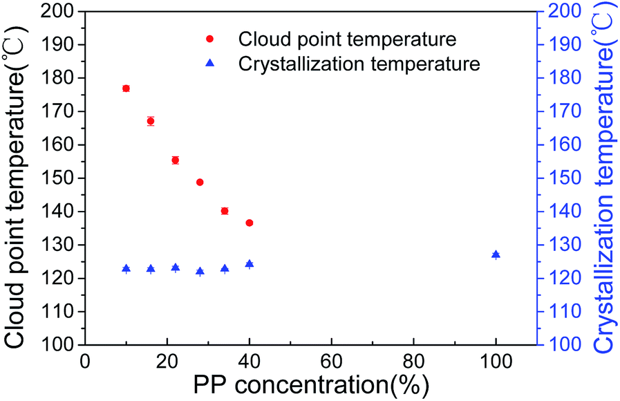 | ||
| Fig. 1 Phase diagram for the PP/binary diluents system with various PP contents: diluents content (SO/CO): 84/16. | ||
Moreover, Fig. 1 shows that the crystallization temperature of PP remains almost constant within the range of PP concentrations studied, which is characteristic of the crystal phase formed in L–L phase separation and is consistent with the results reported previously.20 The crystallization temperature of the original PP in this study was about 127 °C, the addition of binary diluents contributed to this slight decrease.
3.2. Effect of PP concentration on the flat-sheet membrane properties
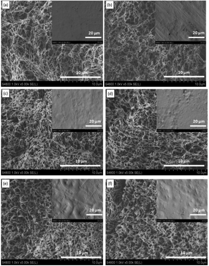 | ||
| Fig. 2 SEM images of PP flat-sheet membranes using various PP concentrations. (PP concentration: (a) 10 wt%; (b) 16 wt%; (c) 22 wt%; (d) 28 wt%; (e) 34 wt%; (f) 40 wt%. Cross-section at magnification 5k and inserts showing the surface at magnification 2k). | ||
The SEM images also show that the pore size of the flat-sheet membranes decreased slightly with an increase in PP concentration. Phase separation was induced by lowering the temperature in the TIPS process. The PP phase formed the membrane skeleton and the diluent phase became the membrane pores upon diluent extraction. Therefore, the increase in PP concentration decreased membrane pore size.27 On the other hand, during the L–L phase separation process, when the PP concentration increased, the L–L phase separation region became smaller, and then the lean-polymer phase grew for a shorter time, so the pore size decreased.19
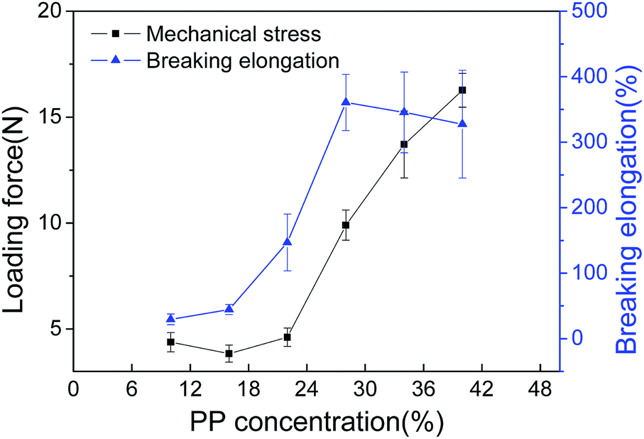 | ||
| Fig. 3 Mechanical properties of PP membranes prepared with different PP concentrations. | ||
The results in Fig. 1 indicated that the PP/SO/CO systems with PP concentrations ranging from 10 wt% to 40 wt% all underwent L–L phase separation. If the PP concentration was higher than 28 wt%, it was difficult to scrape the membranes due to the high viscosity of the casting solution. On the other hand, when the PP concentration was less than 20 wt%, the loading force of the resulting membranes was poor. In addition, the pore size of the membranes decreased with increasing PP concentration. Furthermore, the relatively small pore size was favorable for resistance to water penetration. Therefore, considering the smaller pore size and high mechanical properties, 28 wt% PP was appropriate for this PP/diluents system.
3.3. Characterizations of PP HFM
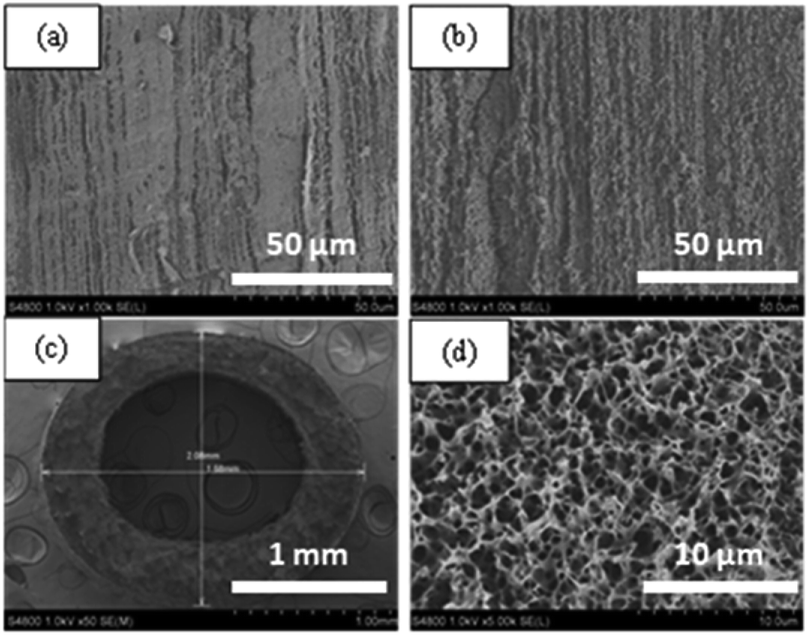 | ||
| Fig. 4 SEM images of PP HFM: (a) inner surface; (b) outer surface; (c) cross-section with magnification 50; (d) cross-section with magnification 5k. | ||
As also shown in Fig. 4, the inner and outer surfaces have no dense skin layer but a loose porous morphology. In PP HFM preparation, diluent-like solvents with a 90/10 mass ratio of SO/CO were applied in both the bore liquid and the outer coagulation baths. The diluent-like solvents had good compatibility with the binary diluents, and could exchange with the casting solution on the inner and outer surfaces to result in a porous structure.26
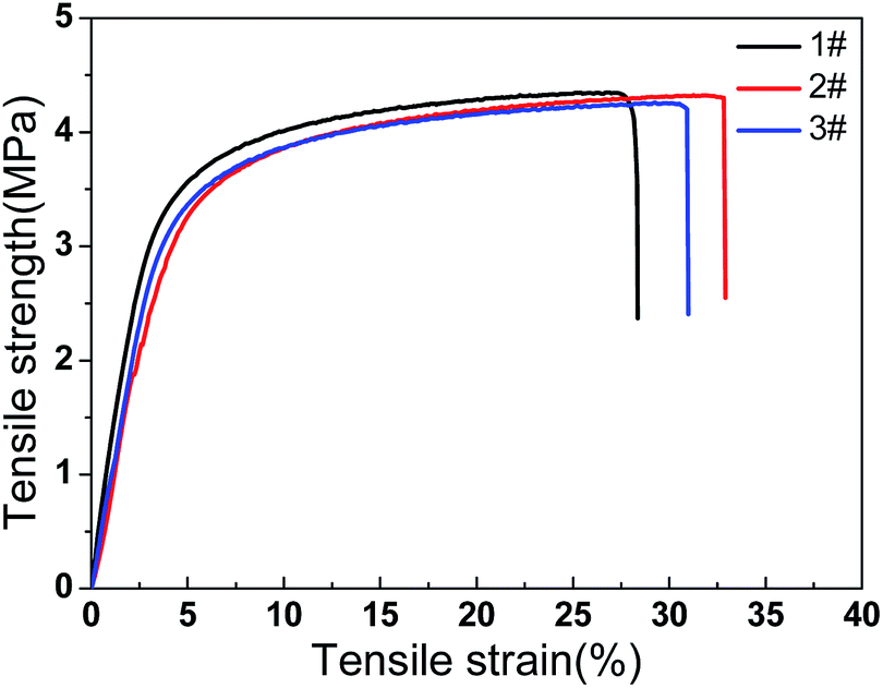 | ||
| Fig. 5 Strength versus strain curves of three parallel tests of PP HFMs. | ||
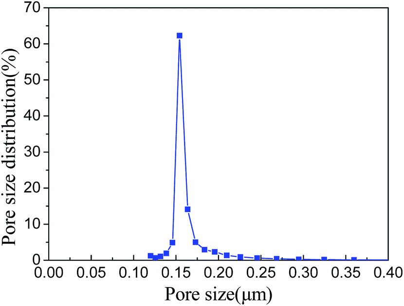 | ||
| Fig. 6 Pore size and pore size distribution of PP HFM. | ||
This narrow pore size structure is helpful for preventing the membrane pore from being wetted and penetrated by water, for a long-term stable performance.
The other properties of PP HFM, including water contact angle (WCA), liquid entering pressure (LEP), etc. are summarized in Table S3 (ESI†).
3.4. Effects of operational parameters on degassing performance
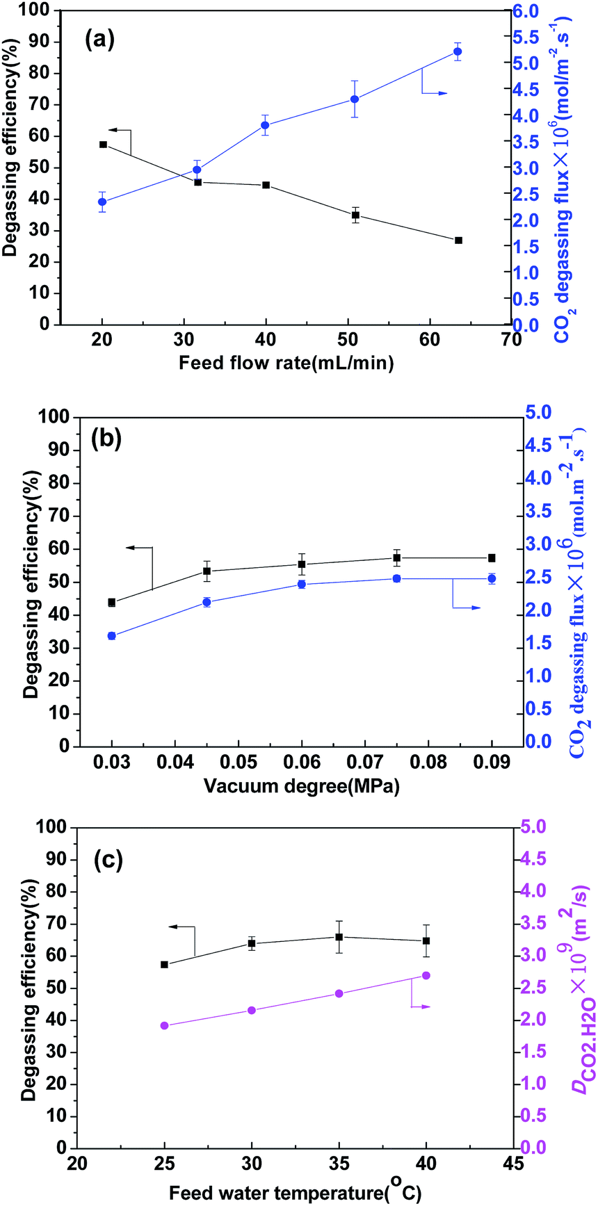 | ||
| Fig. 7 Effects of operational parameters on degassing performance. (a) Feed flow rate; (b) vacuum degree; (c) feed water temperature. (Operating conditions: (a) water temperature of 298 K; vacuum degree of 0.095 MPa. (b) water temperature of 298 K; flow rate of 20 mL min−1 (c) CO2 concentration of 16.5 mg L−1; vacuum degree of 0.095 MPa; flow rate of 20 mL min−1). | ||
However, the degassing flux increased gradually with water flow rate, indicating that the increase in flux was mainly caused by increasing flow rate, although the CO2 concentration change was smaller.28 Hence, in terms of CO2 degassing flux, a higher flow rate was considered to be better. At a higher water flow rate, the mass transfer resistance of the liquid phase became smaller, but the operating energy consumption might increase. However, the flow state was still in the laminar flow region (Reynolds number 126) at a flow rate of 63 mL min−1. This is acceptable considering the fluid resistance energy consumption.
The effect of effective membrane length under two flow rates was investigated and the results are presented in Fig. 8. In Fig. 8(a), when the effective length increased from 0.6 m to 3 m, the CO2 removal efficiency increased. When the length reached 3 m, it was basically stable at about 88%, and the CO2 content of the outlet water declined to 1.6 mg L−1. From Fig. 8(b) for 63 mL min−1, the degassing efficiency of the first circle got smaller. But it increased rapidly in the next two circles. After that, the increase trend slowed down. The final degassing efficiency reached about 87% at 4.8 m. The Reynolds number in the fiber lumen increased from 40 to 126 when the flow rate varied from 20 mL min−1 to 63 mL min−1. The mass transfer at a higher flow rate was enhanced. It was concluded that the degassing performance could be improved with a longer membrane length or at a higher flow rate. For a single membrane module, it seems that only when the membrane is long enough can a desired degassing efficiency be achieved. For a large processing capacity in industrial applications, a higher water flow rate was considered to be better. As for the CO2 removal efficiency, it can be ensured by increasing operation circle times or connecting the modules in series.
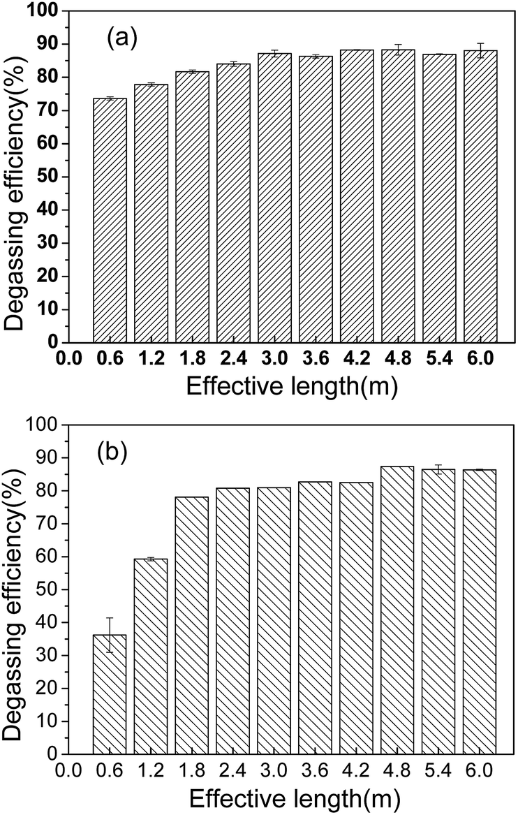 | ||
| Fig. 8 Effect of effective length on degassing efficiency. (Operating conditions: initial CO2 concentration of 16.5 mg L−1; vacuum degree of 0.095 MPa; flow rate of (a) 20 mL min−1 and (b) 63 mL min−1). | ||
4. Conclusions
Hydrophobic PP HFMs prepared via TIPS with environmentally friendly binary diluents were fabricated into a membrane contactor for CO2 degassing from RO effluent water from petrochemical production. The following conclusions were drawn:(1) The phase diagram indicated that the cloud point temperature decreased with PP concentrations from 10 wt% to 40 wt%, but the crystallization temperature was almost stable. The cross-sections of the PP flat-sheet membranes displayed a sponge-like structure. The largest breaking elongation was achieved at 28 wt% PP.
(2) PP HFM showed a sponge-like cross-sectional structure without any dense skin layer, a large loading force and breaking elongation, and a narrow pore size distribution with a mean pore size of 0.16 μm.
(3) When the flow rate increased from 20 mL min−1 to 63 mL min−1, the effective membrane length increased from 3 m to 4.8 m for the best degassing efficiency of about 88%; the amount of treated water or CO2 removed increased by 3.15 times.
Conflicts of interest
There are no conflicts to declare.Acknowledgements
This study was supported by the National Natural Science Foundation of China (No. 21576024) and the project fund under Grant no. 15-16ZS0522 from the Beijing Research Institute of Chemical Industry, SINOPEC.References
- K. Li, I. Chua, N. J. Ng and W. K. Teo, Chem. Eng. Sci., 1995, 50, 3547–3556 CrossRef CAS.
- Z. G. Peng, S. H. Lee, T. Zhou, J. J. Shieh and T. S. Chung, Desalination, 2008, 234, 316–322 CrossRef CAS.
- M. Bassandeh, A. Antony, L. C. Pierre, D. Richardson and G. Leslie, Chemosphere, 2013, 90, 1461–1469 CrossRef CAS PubMed.
- Ö. Arar, Ü. Yüksel, N. Kabay and M. Yüksel, Desalination, 2014, 342, 16–22 CrossRef.
- M. Raffin, E. Germain and S. Judd, Desalin. Water Treat., 2012, 40, 302–308 CAS.
- E. Drioli, E. Curcio and G. Di Profio, Chem. Eng. Res. Des., 2005, 83, 223–233 CrossRef CAS.
- Q. Zhang and E. L. Cussler, J. Membr. Sci., 1985, 23, 321–332 CrossRef.
- E. Kianfar, V. Pirouzfar and H. Sakhaeinia, J. Taiwan Inst. Chem. Eng., 2017, 80, 954–962 CrossRef CAS.
- S. Hosseini and A. Mansourizadeh, J. Taiwan Inst. Chem. Eng., 2017, 76, 156–166 CrossRef CAS.
- M. X. Fang, Z. Wang, S. P. Yan, Q. G. Cen and Z. Y. Luo, Int. J. Greenhouse Gas Control, 2012, 9, 507–521 CrossRef CAS.
- M. Henares, M. Izquierdo, J. M. Penya-Roja and V. Martinez-Soria, Sep. Purif. Technol., 2016, 170, 22–29 CrossRef CAS.
- A. Mansourizadeh and A. F. Ismail, Desalination, 2011, 386, 386–390 CrossRef.
- M. Rahbari-Sisakht, A. F. Ismail, D. Rana, T. Matsuura and D. Emadzadeh, Sep. Purif. Technol., 2013, 108, 119–123 CrossRef CAS.
- S. Khaisri, D. deMontigny, P. Tontiwachwuthikul and R. Jiraratananon, J. Membr. Sci., 2011, 376, 110–118 CrossRef CAS.
- S. Koonaphapdeelert, Z. Wu and K. Li, Chem. Eng. Sci., 2009, 64, 1–8 CrossRef CAS.
- T. Li and T. C. Keener, Int. J. Greenhouse Gas Control, 2016, 51, 290–304 CrossRef CAS.
- S. Rajabzadeh, T. Maruyama, T. Sotani and H. Matsuyama, Sep. Purif. Technol., 2008, 63, 415–423 CrossRef CAS.
- S. Atchariyawut, C. Feng, R. Wang, R. Jiraratananon and D. T. Liang, J. Membr. Sci., 2006, 285, 272–281 CrossRef CAS.
- D. R. Lloyd, S. S. Kim and K. E. Kinzerb, J. Membr. Sci., 1991, 64, 1–11 CrossRef CAS.
- B. Zhou, Y. Tang, Q. Li, Y. Lin, M. Yu, Y. Xiong and X. Wang, J. Appl. Polym. Sci., 2015, 132, 42490 Search PubMed.
- N. Tang, Q. Jia, H. Zhang, J. Li and S. Cao, Desalination, 2010, 256, 27–36 CrossRef CAS.
- W. Yave, R. Quijada, D. Serafini and D. R. Lloyd, J. Membr. Sci., 2005, 263, 146–153 CrossRef CAS.
- G. Chen, Y. K. Lin and X. L. Wang, J. Appl. Polym. Sci., 2007, 105, 2000–2007 CrossRef CAS.
- Y. J. Wang, Z. P. Zhao, Z. Y. Xi and S. Y. Yan, J. Membr. Sci., 2018, 548, 332–344 CrossRef CAS.
- D. R. Lloyd, J. Membr. Sci., 1989, 52, 239–261 CrossRef.
- G. L. Ji, L. P. Zhu, B. K. Zhu, C. F. Zhang and Y. Y. Xu, J. Membr. Sci., 2008, 319, 264–270 CrossRef CAS.
- Z. Cui, N. T. Hassankiadeh, S. Y. Lee, K. T. Woo, J. M. Lee, A. Sanguineti, V. Arcella, Y. M. Lee and E. Drioli, J. Membr. Sci., 2015, 473, 128–136 CrossRef CAS.
- N. A. Rahim, N. Ghasem and M. Al-Marzouqi, J. Nat. Gas Sci. Eng., 2014, 21, 886–893 CrossRef CAS.
- H. Kreulen, C. A. Smolders, G. F. Versteeg and W. P. M. Van Swaaij, Chem. Eng. Sci., 1993, 48, 2093–2102 CrossRef CAS.
Footnote |
| † Electronic supplementary information (ESI) available: Experimental details, comparisons of mechanical properties with literature data, the other properties of fabricated PP hollow fiber membranes. See DOI: 10.1039/c9ra02766a |
| This journal is © The Royal Society of Chemistry 2019 |