
 Open Access Article
 This Open Access Article is licensed under a Creative Commons Attribution-Non Commercial 3.0 Unported Licence
Improving the structural stability and electrochemical performance of Na2Li2Ti6O14 nanoparticles via MgF2 coating†
Wei-Wei
Ma
a,
Hai-Tao
Yu
 a,
Chen-Feng
Guo
a,
Ying
Xie
*a,
Ning
Ren
*b and
Ting-Feng
Yi
*c
a,
Chen-Feng
Guo
a,
Ying
Xie
*a,
Ning
Ren
*b and
Ting-Feng
Yi
*c
aKey Laboratory of Functional Inorganic Material Chemistry, Ministry of Education, School of Chemistry and Materials Science, Heilongjiang University, Harbin, 150080, PR China. E-mail: xieying@hlju.edu.cn
bZhejiang Chilwee Chuangyuan Industry Co., Ltd, Changxing, Zhejiang 313100, PR China. E-mail: rnrm040412@163.com
cSchool of Resources and Materials, Northeastern University at Qinhuangdao, Qinhuangdao, 066004, PR China. E-mail: tfyihit@163.com
First published on 21st May 2019
Abstract
To improve their electrochemical performance and structural stability, Na2Li2Ti6O14 (NLTO) nanoparticles were synthesized and then coated with a very thin MgF2 layer. Microscopy confirmed that the MgF2-NLTO particles are about 150–250 nm in size, and that the thickness of the MgF2 layer for the MgF2-NLTO-5 sample is ∼5 nm. Electrochemical measurements showed that the charge–discharge specific capacities of the five samples under a current density of 50 mA g−1 after 100 cycles are 110.4/110.7, 150.7/151.3, 181.1/182.1, 205.7/206.9 and 238.9/239.2 mA h g−1, showing that the performance of MgF2-NLTO-5 is the best among all the samples. Thanks to the thin coating layer, the polarization of the anode was reduced significantly, and its reversibility and lithium diffusion dynamics were also improved obviously. The performance improvement can be attributed to the suppression of surface corrosion and the enhancement of structural stability.
1. Introduction
Lithium-ion batteries (LIBs) are ubiquitous in our daily lives and serve not only as a means of large-scale energy storage, but also in consumer electronics.1 In recent years, the increasing demand for safe and high power LIBs has stimulated great research interests in advanced electrode materials.2–5 Na2Li2Ti6O14, which has a lower charge–discharge voltage platform (∼1.25 V) than Li4Ti5O12 (1.55 V), is a potential anode material for lithium-ion batteries, and it also exhibits a better ion conductivity and a higher theoretical capacity.6 Therefore, a whole battery composed of this material is expected to have a higher output voltage and a higher multiplying capacity, which will be beneficial for applications in the field of electric vehicles.Although Na2Li2Ti6O14 has many advantages, it still suffers from poor electronic conductivity and sluggish dynamics, which can be solved effectively by nanocrystallization. Aside from the above structural issues, another approach to improve the electrochemical performance of the electrode is to modify the surface status of the materials with inert compounds, to protect against corrosion from the electrolyte. According to previous studies, metal oxides and metal phosphates are commonly used as coating layers.7–15 Nevertheless, it has also been reported that metal oxides and metal phosphates can be converted into corresponding metal fluorides due to the exposure of their surfaces to trace HF in the electrolyte.12–14 For instance, Myung et al. reported that a metal oxide coating layer on Li1.05Ni0.4Co0.15Mn0.4O2 can act as an HF scavenger through the following reaction: Al2O3 + 6HF → 2AlF3 + 3H2O.16,17 Bai et al. reported that the conversion of YPO4 to YF3 happens in a YPO4@LiCoO2 system.12 Moreover, Liu et al. indicated that AlF3 is one of the components of the SEI film formed on the surface of LiCoO2 immersed in an electrolyte containing an Al2O3 additive.14
Enlightened by previous studies, it can be noted that metal fluorides are most likely the ultimate products on the material surfaces which make a substantial contribution to repeated electrochemical cycling. MgF2 with high hardness and good thermal stability is widely applied in various optical films and multilayer photonic crystals.18 Cho et al. successfully coated MgF2 on a LiCoO2 surface, which improves the electrochemical performance of the material.19 Moreover, coating MgF2 on the surface of LiCoO2 and Li[Li0.2Ni0.2Mn0.6]O2 also effectively suppressed their capacity fading.20
To suppress corrosion and improve conductivity simultaneously, coating the nanoparticles with an ultrathin and stable layer offers an effective strategy to significantly improve the electrochemical performance of Na2Li2Ti6O14. Furthermore, for titanium oxide-based anode materials, their electrochemical performance is usually evaluated in the potential window of 1.0 to 3.0 V vs. Li/Li+ to prohibit the formation of an SEI. However, investigations concerning the low potential performance of Na2Li2Ti6O14 are also very important, because they are not only related to energy density but also to safety issues, which are important factors for realistic applications. Our study shows that the coating strategy is workable and that the coated material is very stable and exhibits an excellent electrochemical performance, even discharging down to 0 V. The present study will provide an example for further applications of relevant materials.
2. Experimental section
2.1. Preparation of the samples
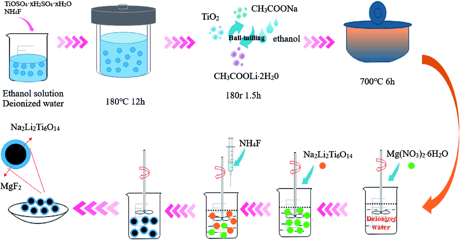
The preparation procedure for pure NLTO and MgF2-coated Na2Li2Ti6O14 is shown in Fig. 1. First, 7.5 mmol titanium sulfate (TiOSO4) and 7.5 mmol ammonium fluoride (NH4F) were mixed with 50 mL of ethanol and 25 mL of distilled water under vigorous stirring. The mixture was placed into a Teflon-lined stainless steel autoclave, and a hydrothermal reaction was carried out at 180 °C for 12 h. After the reaction, the product was collected by centrifugation and then washed 3–4 times with distilled water to remove ionic impurities. Finally, the precursors were dried at 60 °C in air. A solid-state reaction was then applied. The precursors, CH3COOLi·2H2O, and CH3COONa, in a molar ratio of 3![[thin space (1/6-em)]](https://www.rsc.org/images/entities/char_2009.gif) :1:1, were pretreated by planetary high energy ball milling in ethanol for 1.5 h and dried in an oven at 60 °C for 6 h. The as-obtained powder was ground and placed in an alumina boat and calcined at 700 °C for 6 h in an air atmosphere to obtain Na2Li2Ti6O14 nanoparticles.
:1:1, were pretreated by planetary high energy ball milling in ethanol for 1.5 h and dried in an oven at 60 °C for 6 h. The as-obtained powder was ground and placed in an alumina boat and calcined at 700 °C for 6 h in an air atmosphere to obtain Na2Li2Ti6O14 nanoparticles.
 | ||
| Fig. 1 Schematic diagram for the preparation of NLTO and MgF2-coated NLTO samples. | ||
To prepare MgF2-coated Na2Li2Ti6O14 samples, ammonium fluoride (Aldrich) and magnesium nitrate nonahydrate (Aldrich) were separately dissolved in distilled water. After that, Na2Li2Ti6O14 powder was added to the solution. The Mg:F molar ratio was adjusted to 1:2 and the total amounts of MgF2 in the solution were 0 wt%, 1 wt%, 3 wt%, 5 wt%, and 7 wt%. The solutions were constantly stirred at 80 °C for 5 h, and the obtained powders were heated at 400 °C for 5 h in nitrogen. For convenience, the samples with different amount of MgF2 were named as NLTO, MgF2-NLTO-1, MgF2-NLTO-3, MgF2-NLTO-5 and MgF2-NLTO-7.
2.2. Characterization and performance tests
The crystal structure of the samples was studied using a Bruker D8 powder X-ray diffractometer (XRD) and the morphology of the samples was recorded using a scanning electron microscope (SEM, Hitachi S-4800) and a transmission electron microscope (TEM, JEOL2100). Elemental compositions of the sample were characterized via energy dispersive spectroscopy (EDS, Oxford INCA Britain). Electrochemical tests were performed using CR 2025-type coin cells with pure Li foils as counter electrodes. A mixture of the active material, carbon black, and polyvinylidene fluoride (PVDF) with a weight ratio of 8:1:1 was homogeneously dissolved in N-methyl-2-pyrrolidinone (NMP). The slurry was then pasted on a Cu foil current collector, followed by a vacuum drying process at 110 °C for 12 h. The dried foil was then cut into circular wafers 14 mm in diameter, which were used as cathodes to assemble the half cells in an argon-filled glove box. The oxygen and moisture levels in the glove box were both below 0.1 ppm. The electrolyte was a 1 mol L−1 LiPF6 solution dissolved in a 1:1:1 (v/v/v) mixture of ethylene carbonate (EC), diethyl carbonate (DEC) and dimethyl carbonate (DMC). Celgard 2400 films were used as separators. Galvanostatic charge–discharge performance was examined using a LAND CT2001A system between 0 and 3 V (vs. Li+/Li) at different rates. Electrochemical impedance spectroscopy (EIS) tests were performed using a Princeton P4000 workstation over a frequency range from 0.01 Hz to 100 kHz at a potentiostatic signal amplitude of 5 mV. Cyclic voltammetry (CV) tests were carried out using a CHI 1000C electrochemical workstation within a voltage window between 0 and 3 V at a scanning rate of 0.1 mV s−1.
3. Results and discussion
Fig. 2 shows the XRD patterns of pristine and MgF2-coated Na2Li2Ti6O14 powders. It was confirmed that the diffraction peaks of NLTO are identical to those of the standard card for Na2Li2Ti6O14 (PDF #52-0690), indicating that NLTO is well crystalline and without impurities. For all MgF2-coated samples, the characteristic peaks are almost identical, and the coating of MgF2 does not significantly affect the lattice structure of NLTO. Fig. S1† displays the Rietveld refinements of all samples. It can be seen that the simulated peaks well match the experimental ones. The refined lattice parameters and errors are listed in Table S1.† The cell parameters of NLTO are calculated to be a = 5.7370 Å, b = 11.2266 Å and c = 16.4844 Å, and the error (Rwp) is only 5.6%.21 Compared with NLTO, the cell parameters of the MgF2-coated samples are similar, which further proves that the basic structures of MgF2-NLTO remain unchanged after surface modification.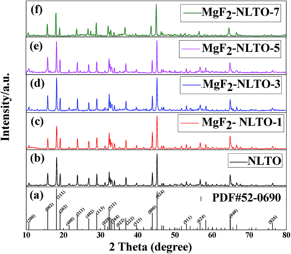 | ||
| Fig. 2 (a) Standard card for NLTO crystal and XRD patterns for (b) NLTO, (c) MgF2-NLTO-1, (d) MgF2-NLTO-3, (e) MgF2-NLTO-5 and (f) MgF2-NLTO-7 samples. | ||
The morphologies of NLTO and MgF2-NLTO samples are displayed in Fig. 3. It can be observed that NLTO nanoparticles with sizes of 150–250 nm aggregate together severely. With a coating of MgF2, the samples became dispersed uniformly, and their size remains almost the same. These results suggest that the MgF2 coating layer is thin and beneficial for the dispersion of the sample. Because of the good dispersion and the small size, stacking of the materials would lead to a relative large void space among particles, which is helpful for the penetration of the electrolyte and for the accommodation of lithium. It can thus be anticipated that coating with MgF2 will improve the electrochemical performance of the materials.
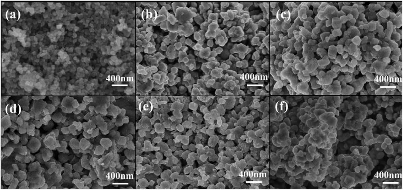 | ||
| Fig. 3 SEM images of (a) TiO2 precursor and (b) pure NLTO, and of NLTO powders coated with different amounts of MgF2: (c) MgF2-NLTO-1, (d) MgF2-NLTO-3, (e) MgF2-NLTO-5 and (f) MgF2-NLTO-7. | ||
To directly observe the microstructure of the MgF2 coating layer, TEM images were recorded and compared. Fig. 4 shows the TEM images of the MgF2-NLTO-5 sample, and the figure clearly shows that the particle size is around 150–250 nm, which is consistent with the SEM results. Furthermore, the lattice fringe near the crystal surface is about 2.55 Å, which corresponds to the interplanar distance of the (022) facet of NLTO,22 while the light spots in the selection area correlate to the (022), (002), (004), (402) and (113) facets of NLTO. In addition, an amorphous layer with a thickness of ∼5 nm can be clearly seen for the MgF2-NLTO-5 sample. This coating layer will separate the NLTO from the electrolyte, avoiding direct contact between them two. Thereby, side reactions could be suppressed and the materials should have better stability against HF corrosion. To provide a composition analysis, elemental mapping testing was performed and the results displayed in Fig. 5. The results demonstrate that sodium, titanium, oxygen, fluorine, and magnesium elements are distributed evenly in the whole region of the nanoparticles, and that the MgF2 layer was coated successfully on the surface of NLTO. These structural changes will be helpful for the enhancement of electrochemical performance.
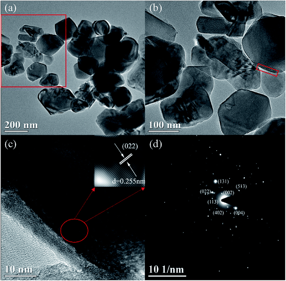 | ||
| Fig. 4 TEM images for (a and b) the MgF2-NLTO-5 sample at different scales, (c) high resolution TEM and relevant lattice fringe in selected area, and (d) SAED pattern. | ||
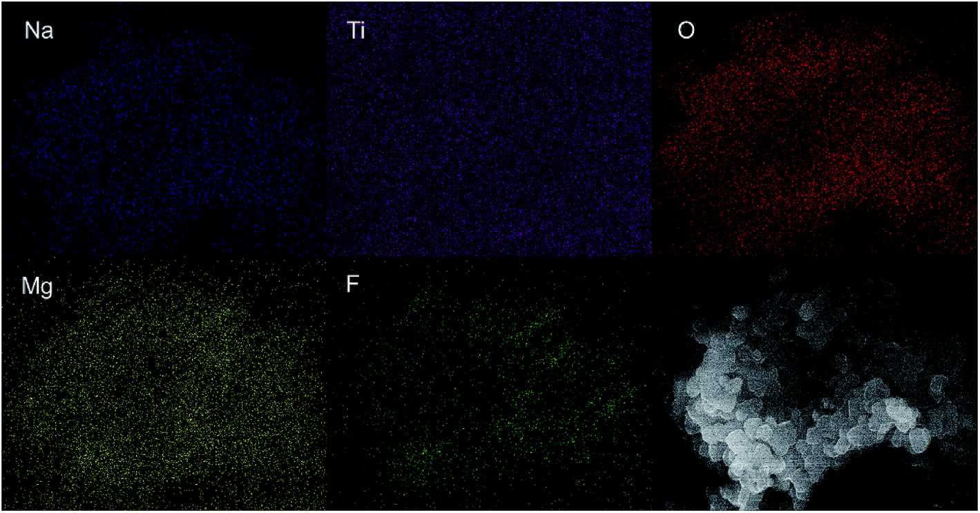 | ||
| Fig. 5 Elemental mapping for Na, Ti, O, Mg, and F species in the MgF2-NLTO-5 sample. | ||
The CV curves of different samples are shown in Fig. 6. Each curve for different cycles only contains a pair of redox peaks, which corresponds to the insertion/extraction of lithium ions into/from the host structure. For NLTO, the redox peaks appear at 1.43 and 1.21 V in the first cycle, which shifts to 1.42 and 1.17 V and then to 1.44 and 1.15 V in the subsequent two cycles. The redox peaks are the signature of the oxidation of Ti3+ and the reduction of Ti4+.23,24 To evaluate the polarization, the potential differences between the oxidation and reduction peaks were calculated and are listed in Table S2.† The results indicate that the polarization of NLTO sample increases persistently in the first three cycles, while that of MgF2-NLTO-5 is nearly unchanged. At the same time, the peak current for MgF2-NLTO-5 remains almost the same (∼0.08 mA) during cycling. The results suggest that the MgF2-NLTO-5 sample is quite stable and possesses the lowest polarization. The highly reversible characteristics and the improved electrochemical performance is ascribed to the enhanced structural stability of NLTO caused by the MgF2 coating.
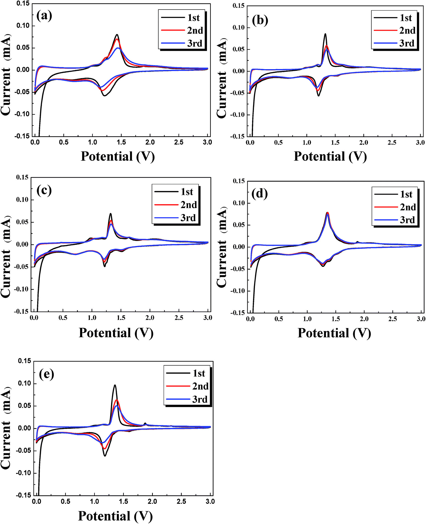 | ||
| Fig. 6 Cyclic voltammograms (CVs) for the (a) NLTO, (b) MgF2-NLTO-1, (c) MgF2-NLTO-3, (d) MgF2-NLTO-5 and (e) MgF2-NLTO-7 samples. | ||
Fig. 7b–f show the charge–discharge curves of different samples. The charge/discharge capacities of NLTO, MgF2-NLTO-1, MgF2-NLTO-3, MgF2-NLTO-5, and MgF2-NLTO-7 in the first cycle were 176.1/292.3, 229.7/384, 216.9/333.4, 267.9/483.4 and 182.3/421.6 mA h g−1, respectively, and their coulombic efficiencies were 60.2%, 59.8%, 65.1%, 55.4% and 43.2%, respectively. The low coulombic efficiencies for the first cycles can be attributed to the formation of a solid electrolyte interface (SEI), the adsorption of lithium ions in the additive, and the irreversible decomposition of the electrolyte.25–28 After 10 cycles, their specific capacities became stable and stayed at 149.2, 200.2, 196.3, 231.4 and 160.5 mA h g−1. After 50 cycles, the five samples still possessed high reversible specific capacities of about 120, 160.1, 180.7, 206.4 and 147 mA h g−1. The cyclic performance and coulombic efficiency of the different samples is displayed in Fig. 7a. It can be seen that the specific capacity of NLTO was 110.7 mA h g−1 after 100 cycles. With an increasing MgF2 coating amount, the specific capacity of the samples increases obviously at first and then decreases when the mass ratio of MgF2 exceeds 7%. This result demonstrates that the introduction of MgF2 as a protection layer will suppress side reactions at the electrode–electrolyte interface and increase the stability of the material. However, an excessive amount of MgF2 coated onto the NLTO surface would hinder the exchange of lithium inbetween the electrolyte and NLTO, also leading to poor electrochemical performance. As a result, MgF2-NLTO-5 has the best performance, and its specific capacity after 100 cycles is 206.9 mA h g−1.
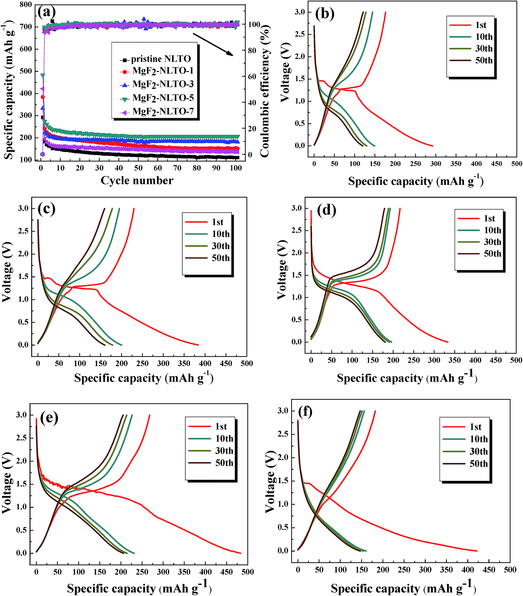 | ||
| Fig. 7 (a) Cycling performance and coulombic efficiency (at 50 mA g−1) for different samples, and charge–discharge curves for the (b) pure NLTO, (c) MgF2-NLTO-1, (d) MgF2-NLTO-3, (e) MgF2-NLTO-5 and (f) MgF2-NLTO-7 samples at the 1st, 10th, 30th and 50th cycles. | ||
The rate performances of the samples and the corresponding charge–discharge curves are depicted in Fig. 8. It can be seen from the figure that there is an obvious voltage platform at about 1.25 V, which is typical electrochemical behavior of NLTO. The MgF2-NLTO samples also show this characteristic platform, indicating that the MgF2 coating does not change the intrinsic structure of NLTO during cycling. Furthermore, it can be identified that the discharge capacity of the pure NLTO decreases sharply with increasing current density. However, MgF2-NLTO samples exhibit much improved performance. In particular, the charge and discharge capacities of MgF2-NLTO-5 (Fig. 8e) both approach 120 mA h g−1 at a current density of 2800 mA g−1. Because of the MgF2 coating, the specific capacities of the MgF2-NLTO samples at each rate (Fig. 8a) increase to different extents, and the performance of MgF2-NLTO-5 is the best among all the samples. Oppositely, continuously increasing the MgF2 coating amount results in capacity degradation. This result demonstrates that a suitable coating amount of MgF2 is crucial for optimizing the performance of NLTO, and that a thick MgF2 coating layer would impede the transport of lithium between NLTO and the electrolyte. In addition, when the current density is reset to 50 mA g−1, the discharge capacity of each sample can be recovered almost to its initial value, which means that the electrochemical reversibility and structural stability of the NLTO host are very good.
 | ||
| Fig. 8 (a) Rate capabilities for different samples, and charge–discharge curves for the (b) pure NLTO, (c) MgF2-NLTO-1, (d) MgF2-NLTO-3, (e) MgF2-NLTO-5 and (f) MgF2-NLTO-7 samples under different current densities. | ||
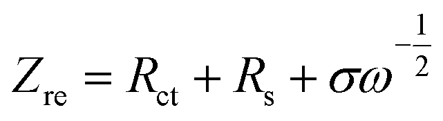
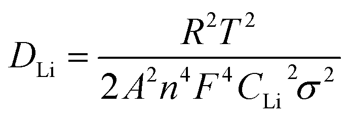
To further study the diffusion dynamics of lithium, EIS measurements of the five samples were obtained and the results are displayed in Fig. 9a. The Nyquist curve consists of a concave semicircle in a high frequency region and a straight line in a low frequency region. The former correlates to the charge transfer resistance (Rct) at the particle–electrolyte interface, while the latter corresponds to the Warburg diffusion process.22 It is found that the Rct of MgF2-NLTO-5 is much smaller than that of the NLTO, MgF2-NLTO-1, MgF2-NLTO-3 and MgF2-NLTO-7 samples, showing that the structure of MgF2-NLTO-5 is favorable for charge transfer at the electrode–electrolyte interface.29
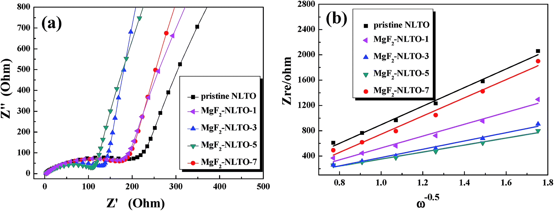 | ||
| Fig. 9 (a) EIS patterns in a frequency range of 10−5 to 10−2 Hz with an amplitude of 5 mV and (b) Zre dependence of ω−0.5 in the low frequency region for different samples. | ||
Based on Fig. 9a, the diffusion coefficient of lithium ions (DLi) can also be calculated by,30–32
 | (1) |
 | (2) |
4. Conclusions
MgF2 was successfully coated on the surface of NLTO nanoparticles via a simple chemical deposition method. Experimental results show that MgF2-NLTO-5 exhibits the optimal electrochemical performance. Homogeneous coating of MgF2 on NLTO surface is favorable for the dispersion of the nanoparticles, and it also improves the structural stability of NLTO against corrosion by the electrolyte. As a result, the specific capacity, rate capability, and long-term cycling stability are all improved obviously. Our experiments demonstrate that the combination of nanocrystallization and surface coating techniques is an effective strategy to improve the electrochemical performance of NLTO, which may be helpful for the design and optimization of relevant electrode materials.Conflicts of interest
There are no conflicts to declare.Acknowledgements
This work was financially supported by the National Natural Science Foundation of China (No. 21773060 and 51774002), Fundamental Research Funds for the Central Universities (No. N182304014), Natural Science Foundation of Heilongjiang Province (E2016056), Fundamental Research Funds for Heilongjiang University of Heilongjiang Province (HDRCCX-2016Z03), Youth Innovation Team Project of Science and Technology of Heilongjiang University (RCYJTD201803), and Young Scholar Project of the Long Jiang Scholars Program (Q201818).References
- J. Lee, A. Urban, X. Li, D. Su, G. Hautier and G. Ceder, Science, 2014, 343, 519–522 CrossRef CAS PubMed.
- X. F. Zhang, I. Belharouak, L. Li, Y. Lei, J. W. Elam, A. Nie, X. Q. Chen, R. S. Yassar and R. L. Axelbaum, Adv. Energy Mater., 2013, 3, 1299–1307 CrossRef CAS.
- B. Dunn, H. Kamath and J. M. Tarascon, Science, 2011, 334, 928–935 CrossRef CAS PubMed.
- X. L. Wu, Y. G. Guo, J. Su, J.-W. Xiong, Y. L. Zhang and L. J. Wan, Adv. Energy Mater., 2013, 3, 1155–1160 CrossRef CAS.
- L. Zeng, C. Zheng, C. Deng, X. Ding and M. Wei, ACS Appl. Mater. Interfaces, 2013, 5, 2182–2187 CrossRef CAS PubMed.
- D. Dambournet, I. Belharouak and K. Amine, Inorg. Chem., 2010, 49, 2822–2826 CrossRef CAS PubMed.
- Y. Wu and A. Manthiram, Electrochem. Solid-State Lett., 2006, 9, 221–224 CrossRef.
- J. Liu, B. Reeja-Jayan and A. Manthiram, J. Phys. Chem. C, 2010, 114, 9528–9533 CrossRef CAS.
- Y. K. Sun, Y. S. Lee, M. Yoshio and K. S. Amine, Electrochem. Solid-State Lett., 2002, 5, 99–102 CrossRef.
- J. Cho, T. J. Kim, J. Kim, M. Noh and B. Park, J. Electrochem. Soc., 2004, 151, 1899–1904 CrossRef.
- Y. Bai, Q. Chang, Q. Yu, S. Zhao and K. Jiang, Electrochim. Acta, 2013, 112, 414–421 CrossRef CAS.
- Y. Bai, Y. Yin, N. Liu, B. Guo, H. Shi, J. Liu, Z. Wang and L. Chen, J. Power Sources, 2007, 174, 328–334 CrossRef CAS.
- S. T. Myung, K. Izumi, S. Komaba, Y. K. Sun, H. Yashiro and N. Kumagai, Chem. Mater., 2005, 17, 3695–3704 CrossRef CAS.
- J. Y. Liu, N. Liu, D. T. Liu, Y. Bai, L. H. Shi, Z. X. Wang, L. Q. Chen, V. Hennige and A. Schuch, J. Electrochem. Soc., 2007, 154, 55–63 CrossRef.
- J. M. Zheng, M. Gu, J. Xiao, B. J. Polzin, P. F. Yan, X. L. Chen, C. M. Wang and J. G. Zhang, Chem. Mater., 2014, 26, 6320–6327 CrossRef CAS.
- S. T. Myung, K. Izumi, S. Komaba, H. Yashiro, H. J. Bang, Y.-K. Sun and N. Kumagai, J. Phys. Chem. C, 2007, 111, 4061–4067 CrossRef CAS.
- Q. L. Xie, Z. B. Hu, C. H. Zhao, S. R. Zhang and K. Y. Liu, RSC Adv., 2015, 5, 50859–50864 RSC.
- Y. Bai, K. Jiang, S. Sun, Q. Wu, X. Lu and N. Wan, Electrochim. Acta, 2014, 134, 347–354 CrossRef CAS.
- Y. Cho, J. Eom and J. Cho, J. Electrochem. Soc., 2010, 157, 617–624 CrossRef.
- H. J. Lee and Y. J. Park, Solid State Ionics, 2013, 230, 86–91 CrossRef CAS.
- D. Dambournet, K. W. Chapman, M. V. Koudriachova, P. J. Chupas, I. Belharouak and K. Amine, Inorg. Chem., 2011, 50, 5855–5857 CrossRef CAS PubMed.
- K. Q. Wu, J. Shu, X. T. Lin, L. Y. Shao, P. Li, M. Shui, N. P. Long and D. J. Wang, J. Power Sources, 2015, 275, 419–428 CrossRef CAS.
- K. Q. Wu, J. Shu, X. T. Lin, L. Y. Shao, P. Li, M. Shui, M. M. Lao, N. P. Long and D. J. Wang, Electrochim. Acta, 2015, 173, 595–606 CrossRef.
- S. Y. Yin, C. Q. Feng, S. J. Wu, H. L. Liu, B. Q. Ke, K. L. Zhang and D. H. Chen, J. Alloys Compd., 2015, 642, 1–6 CrossRef CAS.
- P. F. Wang, P. Li, T. F. Yi, X. T. Lin, H. X. Yu, Y.-R. Zhu, S. S. Qian, M. Shui and J. Shu, J. Power Sources, 2015, 297, 283–294 CrossRef CAS.
- W. J. H. Borghols, M. Wagemaker, U. Lafont, E. M. Kelder and F. M. Mulder, J. Am. Chem. Soc., 2009, 131, 17786–17792 CrossRef CAS PubMed.
- T. F. Yi, Y. Xie, J. Shu, Z. H. Wang, C. B. Yue, R. S. Zhu and H. B. Qiao, J. Electrochem. Soc., 2011, 158, 266–274 CrossRef.
- T. F. Yi, S. Y. Yang and Y. Xie, J. Mater. Chem. A, 2015, 3, 5750–5777 RSC.
- O. Toprakci, H. A. K. Toprakci, Y. Li, L. W. Ji, L. G. Xue, H. Lee, S. Zhang and X. W. Zhang, J. Power Sources, 2013, 241, 522–528 CrossRef CAS.
- S. Y. Yang, J. Yuan, Y. R. Zhu, T. F. Yi and Y. Xie, Ceram. Int., 2015, 41, 7073–7079 CrossRef CAS.
- M. M. Lao, P. Li, X. T. Lin, L. Y. Shao, M. Shui, N. B. Long, D. J. Wang and J. Shu, RSC Adv., 2015, 5, 41999–42008 RSC.
- C. J. Jafta, K. I. Ozoemena, M. K. Mathe and W. D. Roos, Electrochim. Acta, 2012, 85, 411–422 CrossRef CAS.
- Y. S. Hu, L. Kienle, Y. G. Guo and J. Maier, Adv. Mater., 2006, 18, 1421–1426 CrossRef CAS.
- T. F. Yi, S. Y. Yang, X. Y. Li, J. H. Yao, Y. R. Zhu and R. S. Zhu, J. Power Sources, 2014, 246, 505–511 CrossRef CAS.
Footnote |
| † Electronic supplementary information (ESI) available. See DOI: 10.1039/c9ra02392e |
| This journal is © The Royal Society of Chemistry 2019 |