 Open Access Article
Sulfonic acid functionalized metal–organic framework (S-IRMOF-3): a novel catalyst for sustainable approach towards the synthesis of acrylonitriles†
Ryhan Abdullah Rather and
Zeba N. Siddiqui *
*
Department of Chemistry, Aligarh Muslim University, Aligarh 202002, Uttar Pradesh, India. E-mail: siddiqui_zeba@yahoo.co.in
First published on 21st May 2019
Abstract
A sulfonic acid functionalized metal–organic framework (S-IRMOF-3) has been synthesized by dropwise addition of chlorosulfonic acid (0.5 mL) in IRMOF-3 (1 g) containing 20 mL of CHCl3 at 0 °C under simple stirring. The catalyst was applied in Knoevenagel condensation of various aromatic and hetero-aromatic aldehydes forming acrylonitrile derivatives. The catalyst was characterized thoroughly by using FT-IR, XRD, 13C MAS NMR, SEM, EDX, elemental mapping, TEM, BET, NH3-TPD and TGA/DTA techniques. The presence of characteristic bands at 1694 cm−1, 1254–769 cm−1 and 1033 cm−1 in the FT-IR spectrum, 2θ ≃ 6.7° and 9.8° in the XRD pattern and δ = 31.79, 39.55, 129.61, 131.46 (4C, CH), 133.54, 140.07 (2C), 167.71, 171.47 ppm (2C, 2C![[double bond, length as m-dash]](https://www.rsc.org/images/entities/char_e001.gif) O) in the solid state 13C MAS NMR spectrum confirmed the successful formation of catalyst. This new eco-friendly approach resulted in a significant improvement in the synthetic efficiency (90–96% yield), high product purity, and minimizing the production of chemical wastes without using highly toxic reagents for the synthesis of acrylonitriles with selectivity for (Z)-isomer. Steric interactions seem to have an influence on the control of the Z-configurational isomers. By performing DFT calculations, it was found that the (Z)-isomer 3a is stabilized by 1.64 kcal mol−1 more than the (E)-isomer. The catalyst could be reused for five consecutive cycles without substantial loss in catalytic activity.
O) in the solid state 13C MAS NMR spectrum confirmed the successful formation of catalyst. This new eco-friendly approach resulted in a significant improvement in the synthetic efficiency (90–96% yield), high product purity, and minimizing the production of chemical wastes without using highly toxic reagents for the synthesis of acrylonitriles with selectivity for (Z)-isomer. Steric interactions seem to have an influence on the control of the Z-configurational isomers. By performing DFT calculations, it was found that the (Z)-isomer 3a is stabilized by 1.64 kcal mol−1 more than the (E)-isomer. The catalyst could be reused for five consecutive cycles without substantial loss in catalytic activity.
Introduction
Although the story of metal–organic frameworks (MOFs) had already begun earlier in the 20th century,1,2 the intensive development of MOF chemistry was initiated in the mid-nineties.3 This new area of research has caught the attention of many academic and industrial researchers leading to a lot of innovations and discoveries that can be traced in the literature over the past two decades.4 Several aspects such as the surprisingly intrinsic properties as well as the structural diversity of MOFs afford an almost infinite number of possible structures and make MOFs the subject of extensive research. The MOFs which are synthesized by self-assembly of metal ions or clusters with polytopic organic linkers5 have attracted much attention in heterogeneous catalysis due to their intriguing features such as extraordinarily large surface area, well-defined pore structure, easily tailorable chemistry, and high acid–base catalytic activities.6 Because of their high intrinsic metal loading, they have been intensively studied as catalysts in various reactions such as aldol condensation,7 Suzuki coupling,8 Friedel–Crafts reactions,9 Biginelli reaction,10 Claisen–Schmidt condensation,11 Beckmann rearrangement,12 Sonogashira reaction,13 polymerization14 etc. In recent years there has been remarkable growth in the synthesis of MOFs, largely due to their potential applications in gas storage, separations, catalysis, nonlinear optics, magnetic and electronic materials, and so on.15,16 Different heterogeneous MOF-based catalysts have been formulated over the past few decades by introducing different types of catalytic sites into porous MOF matrices.17,18 Keeping in view all these eye-catching properties, MOFs could be promising materials for applications in heterogeneous catalysis and can be employed as solid catalysts or catalyst supports for a variety of organic transformations.Functionalized sulfonic acid has been used to catalyze a variety of reactions.19 Integration of acidic functional groups (e.g., –SO3H) on different support materials has produced promising solid acids20 which have shown improved reaction properties over conventional homogeneous or heterogeneous catalysts for a wide range of acid-catalyzed reactions, including condensation and addition,21 esterification,22 rearrangement,23 Friedel–Crafts acylation,24 alkylation25 and conversion of biorenewable molecules.26 Taking into account the catalytic performance of sulfonic acid functional groups (–SO3H) in organic synthesis, we have tried to incorporate them on MOF surface, with the aim of combining the properties of MOF and SO3H groups and thereby increasing the catalytic activity of the resultant catalyst.
Over the past few decades there has been an increasing dominance in the number of biologically active compounds that contain an acrylonitrile moiety.27 The reactivity of heteroaryl acetonitriles has been employed for the synthesis of some nitrogen-bridged heterocycles.28 Acrylonitrile derivatives are useful intermediates and scaffolds which possess a wide range of favorable biotic assets such as antiproliferative,29 antifungal,30 antitumor,31 antibacterial,32 antitubercular,33 insecticidal,34 hypotensive,35 tuberculostatic,36 AChE inhibitive37 and antiparasitic properties.38 It was recently reported that 2-acetyl-3-(6-methoxybenzothiazo)-2-ylaminoacrylonitrile possesses significant anti-proliferative activity and is an effective inducer of programmed cell death in human leukemia cells.39 The synthesis of acrylonitrile compounds has previously been achieved by the use of Wittig reactions,40 McMurry coupling reactions41 and the Heck reaction.42 Among different methods, Knoevenagel condensation is a simple and straightforward approach for the synthesis of acrylonitrile derivatives.43 This method involves the acid- or base-catalyzed condensation of active methylene moieties with carbonyl compounds. Earlier investigations for this approach required long reaction times, the use of hazardous reagents and tedious workup procedures.
In view of the above considerations and copious biological applications of acrylonitrile derivatives and in continuation of our ongoing research44 on supported heterogeneous catalysts, we herein explored the use of a catalyst, sulfonic acid functionalized IRMOF-3 (S-IRMOF-3), for the synthesis of acrylonitrile derivatives using Knoevenagel condensation. The catalyst S-IRMOF-3 proved to be a sustainable alternative having good catalytic activity and recyclability and more importantly enhancing the rate of product formation.
Results and discussion
The synthesis of S-IRMOF-3 is outlined in Scheme 1.Catalyst characterization
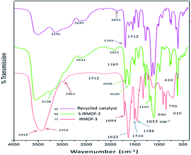
The FT-IR spectra of IRMOF-3, S-IRMOF-3 and recycled S-IRMOF-3 are shown in Fig. 1. The FT-IR spectrum of IRMOF-3 displayed an absorption band at 2961 cm−1 assigned to C–H stretching vibration. The strong peak appearing at 1694 cm−1 was attributed to C![[double bond, length as m-dash]](https://www.rsc.org/images/entities/char_e001.gif) O stretching vibration of the carboxylate group of IRMOF-3.45 The characteristic peak at 1622 cm−1 corresponded to conjugated C
O stretching vibration of the carboxylate group of IRMOF-3.45 The characteristic peak at 1622 cm−1 corresponded to conjugated C![[double bond, length as m-dash]](https://www.rsc.org/images/entities/char_e001.gif) C stretching and the peak at 1388 cm−1 was associated with O–H bending deformation in –COOH.45 Peaks in the range of 1254–769 cm−1 were attributed to the in-plane vibration of the BDC group.46a The two peaks in the range of 769–900 cm−1 were assigned to
C stretching and the peak at 1388 cm−1 was associated with O–H bending deformation in –COOH.45 Peaks in the range of 1254–769 cm−1 were attributed to the in-plane vibration of the BDC group.46a The two peaks in the range of 769–900 cm−1 were assigned to ![[double bond, length as m-dash]](https://www.rsc.org/images/entities/char_e001.gif) CH aromatic plane bends, which showed that the phenyl ring is 1,4-substituted. The symmetric stretching vibration of Zn–O appearing at 610 cm−1 is also consistent with the literature.46b Peaks at 3450 and 3350 cm−1 were attributed to the asymmetric and symmetric stretching absorptions of primary amine group respectively. One of the stretching frequencies of the amine group of the NH2H2BDC linker disappeared after formation of the SO3H@IRMOF-3 composites, suggested occurrence of the NHSO3H group which was confirmed by the sharp peak appearing at 1193 cm−1. Furthermore the band at 1033 cm−1 corresponded to the O
CH aromatic plane bends, which showed that the phenyl ring is 1,4-substituted. The symmetric stretching vibration of Zn–O appearing at 610 cm−1 is also consistent with the literature.46b Peaks at 3450 and 3350 cm−1 were attributed to the asymmetric and symmetric stretching absorptions of primary amine group respectively. One of the stretching frequencies of the amine group of the NH2H2BDC linker disappeared after formation of the SO3H@IRMOF-3 composites, suggested occurrence of the NHSO3H group which was confirmed by the sharp peak appearing at 1193 cm−1. Furthermore the band at 1033 cm−1 corresponded to the O![[double bond, length as m-dash]](https://www.rsc.org/images/entities/char_e001.gif) S
S![[double bond, length as m-dash]](https://www.rsc.org/images/entities/char_e001.gif) O stretching in SO3H group.
O stretching in SO3H group.
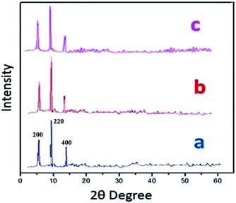
Powder X-ray diffraction (PXRD) data were obtained in order to evaluate S-IRMOF-3 structural stability/homogeneity. Fig. 2 compares PXRD patterns of neat IRMOF-3 and S-IRMOF-3. For the neat IRMOF-3 specimen, the characteristic peaks at 2θ ≃ 6.7°, 9.8° and 13.9° which corresponded to (200), (220) and (400) planes respectively confirmed the successful synthesis of IRMOF-3 (Fig. 2a).47 For S-IRMOF-3, the same characteristic diffraction peaks at 2θ ≃ 6.7°, 9.8° and 13.8° were observed with no other notable changes in the peak patterns and indicated that both IRMOF-3 and S-IRMOF-3 had the same structure phase.
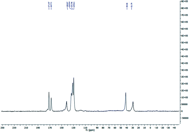
The solid state 13C MAS nuclear magnetic resonance (13C MAS NMR) spectrum of S-IRMOF-3 is depicted in Fig. 3. The spectrum indicated eight peaks which corresponded to δ = 31.79, 39.55, 129.61, 131.46 (4C, CH), δ = 133.54, 140.07 (2C), δ = 167.71, 171.47 ppm (2C, 2C![[double bond, length as m-dash]](https://www.rsc.org/images/entities/char_e001.gif) O) supporting the structure of IRMOF-3. The signals at δ = 31.79 and 39.55 ppm were due to trapped DMF solvent molecule in S-IRMOF-3.48
O) supporting the structure of IRMOF-3. The signals at δ = 31.79 and 39.55 ppm were due to trapped DMF solvent molecule in S-IRMOF-3.48
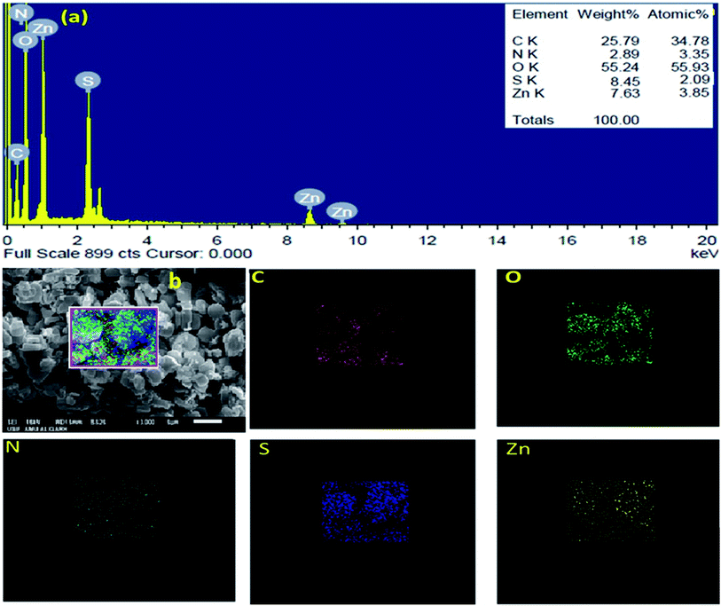
The SEM images of IRMOF-3 and the catalyst S-IRMOF-3 at different magnifications are shown in Fig. 4. There were slight changes in the surface morphology of S-IRMOF-3 (Fig. 4b) as compared to IRMOF-3 (Fig. 4a) due to surface SO3H groups. The EDX analysis (Fig. 5a) showed the presence of C, O, S, Zn and N elements, while the elemental mapping of C, O, N, S and Zn elements of S-IRMOF-3 (Fig. 5b) clearly demonstrates that SO3H groups were well distributed into the surfaces of S-IRMOF-3.
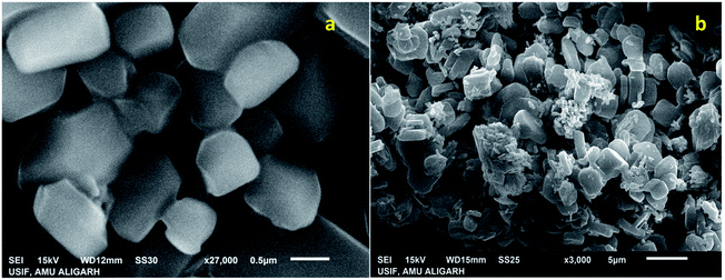 | ||
| Fig. 4 SEM images of (a) IRMOF-3 and (b) the synthesized catalyst (S-IRMOF-3) at different magnifications. | ||
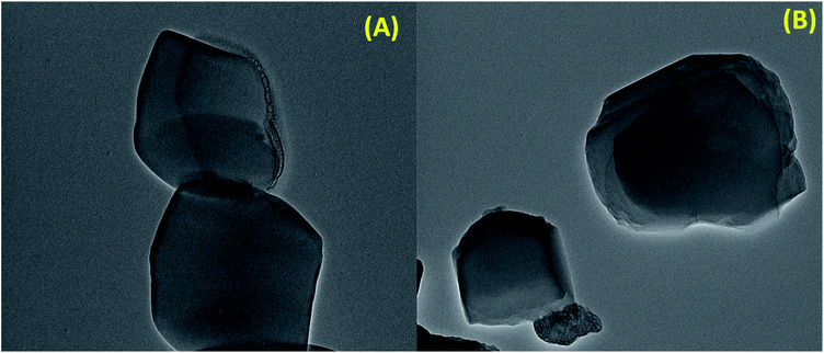
In order to further observe the morphology of S-IRMOF-3, TEM images were obtained. It can be seen from the contrast TEM image of S-IRMOF-3 (Fig. 6A) that it presents a cube like structure that corresponds to the fact that IRMOF-3 was not altered during functionalization of IRMOF-3. The dark shades that are observed in the TEM images of S-IRMOF-3 are attributed to sulfonic acid system homogeneously dispersed on the surfaces of IRMOF-3 composite. There is no further change in the TEM image of recycled S-IRMOF-3 (Fig. 6B).
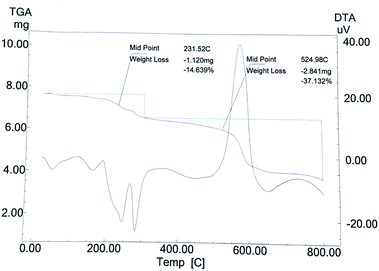
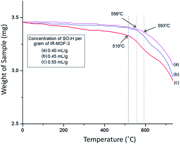
The TG curve (Fig. 7) of catalyst S-IRMOF-3 recorded a first weight loss at 231 °C caused by the removal of DMF and a second weight loss at 524 °C due to removal of SO3H group.49 S-IRMOF-3 with different weight percentages showed high thermal stability up to 550 °C while that of pure IRMOF-3 was up to 440 °C.50 The catalyst then did not show any further weight loss up to 550 °C. This confirmed that the catalyst was stable up to this temperature as shown also by DT analysis. In addition, the DT analysis curve showed a sharp peak at around 590 °C which confirmed the exothermic nature of the catalyst (Fig. 7). Thus, TG and DT analyses showed that the catalyst can tolerate a wide range of temperature. Furthermore, the thermal stability of the catalyst was also confirmed by varying the SO3H content. It was observed that thermal stability of the catalyst was reduced on increasing the concentration of SO3H from 0.40 mL g−1 to 055 mL g−1 as shown in Fig. 8. At the same time, the activity of the catalyst was enhanced due to an increase in acidity of the catalyst (Table S1†).
The specific surface area and pore volume of IRMOF-3 and S-IRMOF-3 were calculated using the Brunauer–Emmett–Teller (BET) method. The surface area of IRMOF-3 was reduced from 1342 m2 g−1 to 1299 m2 g−1 (Fig. 9a and b) and pore volume reduced from 0.061 cm3 g−1 to 0.050 cm3 g−1 (Fig. 9c and d). The reduction of surface area and pore volume may be due to sulfonic acid functionalization of IRMOF-3.
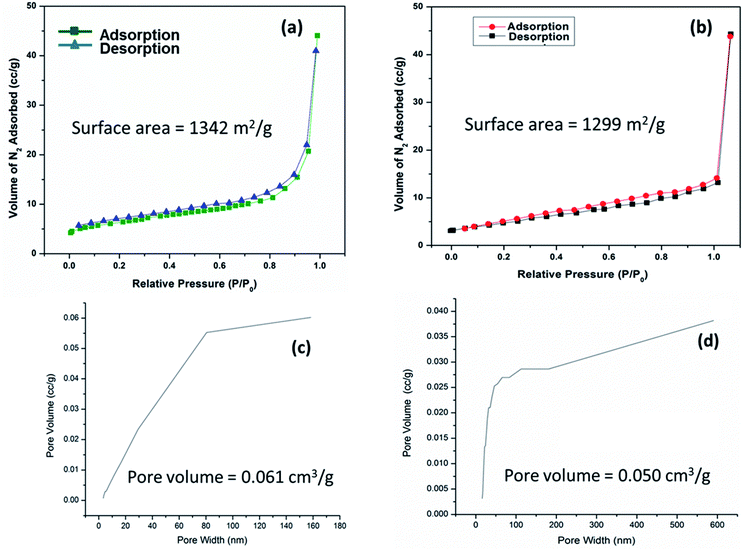 | ||
| Fig. 9 N2 adsorption isotherms of (a) IRMOF-3 and (b) S-IRMOF-3. PSD of (c) IRMOF-3 and (d) S-IRMOF-3. | ||
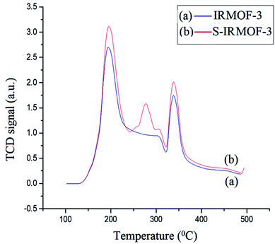
The acidic sites of IRMOF-3 and S-IRMOF-3 were compared using NH3-TPD measurement (Fig. 10). The NH3 desorption peaks for IRMOF-3 indicated different adsorption sites for the ammonia species with different thermal stabilities. The low-temperature (188 °C) desorption peak was attributed to ammonium species adsorbed at Lewis acid sites, while the high-temperature (336 °C) desorption peak was assigned to high thermal adsorption of ammonium species on Brønsted acid sites.51 It was observed that after the sulfonic acid functionalization, an additional peak at 281 °C appeared in NH3-TPD measurements of S-IRMOF-3 which may be due to SO3H groups on the IRMOF-3 framework.52
Optimization of reaction conditions
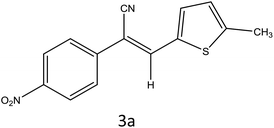
To investigate the viability of our protocol for the synthesis of various acrylonitrile derivatives, a sequence of experiments were carried out using 3-methyl-2-thiophenecarboxaldehyde and p-nitrophenylacetonitrile as model substrates. Several controlled experiments were performed, first without any catalyst and subsequently using PTSA, acetic acid, and chlorosulfonic acid as catalysts in ethanol at ambient temperature, the results being found to be unsatisfactory (Table 1, entries 1 to 4). Use of basic catalyst such as piperidine and NaOMe also did not work (Table 1, entries 5 and 6). Application of MOFs (including IRMOF-3), however, showed encouraging results (Table 1, entries 8 and 9). Finally when S-IRMOF-3 was used (Table 1, entry 10) the reaction proceeded smoothly affording excellent yield of the product. The reaction conditions were further optimized by examining the solvent effect on the reaction. The reaction was first tested under solvent-free conditions by the grinding method; however only traces of product were obtained (Table 2, entry 1). When the reaction was carried out in different protic and aprotic solvents, the best results in terms of yield (96%) and time period (30 min) were obtained with ethanol (Table 2, entry 2). In order to find the optimized amount of the catalyst, the reaction was carried out by varying the amount of the catalyst in the model reaction (Table 3). It was found that the yield of the acrylonitrile derivatives increased linearly with an increase in the amount of catalyst from 50 to 200 mg (Table 3, entries 1–4). Further increase in the amount of catalyst did not have any profound effect on the reaction (Table 3, entry 5). Therefore, 200 mg of S-IRMOF-3 was used for the synthesis of acrylonitriles.| Entry | Catalyst | Timeb | Yieldc (%) |
|---|---|---|---|
| a Reaction conditions: 5-methyl-2-thiophenecarboxaldehyde (1a, 1 mmol), p-nitrophenylacetonitrile (1 mmol), different catalysts (2.5 mol%), EtOH (10 mL).b Reaction progress monitored by TLC.c Isolated yield of products. | |||
| 1 | — | 12 h | Traces |
| 2 | PTSA | 5.5 h | 58 |
| 3 | Acetic acid | 4.6 h | 50 |
| 4 | Chlorosulfonic acid | 3.5 h | 62 |
| 5 | Piperidine | 4.5 h | 60 (impure) |
| 6 | Sodium methoxide | 8 h | 56 (impure) |
| 7 | Cl–SiO2 | 2 h | 88 |
| 8 | MOF-5(T) | 1.5 h | 78 |
| 9 | IRMOF-3 | 1.5 h | 80 |
| 10 | S-IRMOF-3 | 30 min | 96 |
| Entry | Solvent | Timeb | Yieldc (%) |
|---|---|---|---|
| a Reaction conditions: 5-methyl-2-thiophenecarboxaldehyde (1a, 1 mmol), p-nitrophenylacetonitrile (1 mmol), catalyst (2.5 mol%), different solvents (10 mL).b Reaction progress monitored by TLC.c Isolated yield of products.d Solvent-free by grinding method. | |||
| 1 | Solvent freed | — | Traces |
| 2 | Ethanol | 30 min | 96 |
| 3 | Methanol | 2 h | 74 |
| 4 | Acetonitrile | 3 h | 68 |
| 5 | Water | 6 h | 60 |
| 6 | Chloroform | 4 h | 58 |
| 7 | Isopropanol | 5 h | 55 |
| 8 | DMF | 6 h | 52 |
| 9 | Acetic acid | 7 h | 70 |
| 10 | PEG-200 | 8 h | 48 |
| 11 | PEG-400 | 7 h | 46 |
| 12 | PEG-600 | 7 h | 46 |
| Entry | Catalyst (mg) | Timeb | Yieldc (%) |
|---|---|---|---|
| a Reaction conditions: 5-methyl-2-thiophenecarboxaldehyde (1a, 1 mmol), p-nitrophenylacetonitrile (1 mmol), EtOH solvent.b Reaction progress monitored by TLC.c Isolated yield of products. | |||
| 1 | 50 | 1.5 h | 80 |
| 2 | 100 | 1.0 h | 88 |
| 3 | 150 | 50 min | 92 |
| 4 | 200 | 30 min | 96 |
| 5 | 250 | 30 min | 96 |
Catalytic reaction
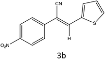
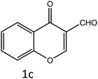
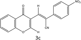
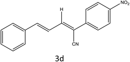
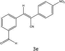
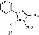
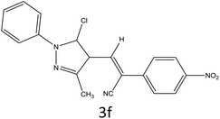
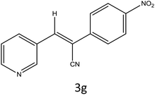
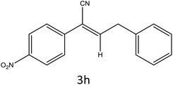
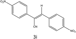
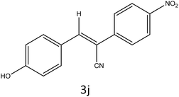
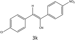
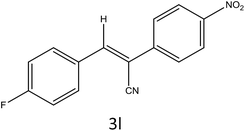
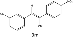
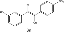
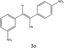
After optimization of reaction conditions, the substrate scope of the S-IRMOF-3-catalyzed synthesis of acrylonitrile derivatives (Scheme 2) was examined (Table 4). The results showed that the reaction proceeded efficiently with both aromatic as well as hetero-aromatic aldehydes bearing both electron-releasing and electron-withdrawing groups.Reaction mechanism
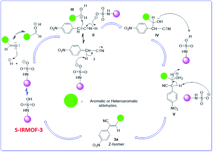
A plausible mechanism for the synthesis of acrylonitrile derivative 3a is outlined in Scheme 3. Among the two possible isomers (E and Z), the (Z)-isomer was obtained as the sole product (Scheme 3). This Z-selectivity can be inferred as a way to minimize steric interactions between the approaching nucleophile (imide form of p-nitrophenylacetonitrile), the bulky aryl substituent and catalyst-bound electron-deficient carbonyl carbon. It favors back-side attack of the nucleophile in such a way that the phenyl ring of the approaching nucleophile is pushed away, thus facilitating the formation of the (Z)-isomer. Steric interactions seem to have an influence on the control of the Z-configurational isomers. This is further supported by DFT calculations.Catalyst recycling
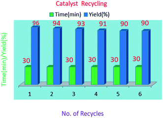
The reusability of the S-IRMOF-3 catalyst was also examined in a model reaction. The catalyst was reused five times and the results show that the catalyst can be reused without a significant drop in product yield (Table 5). The reusability of the catalyst reduces the cost of the reaction. After the first fresh run with 96% yield (Table 5, entry 1), the catalyst was removed by filtration. The recovered catalyst was dried under vacuum at 120 °C for 10 h and tested for five more reaction cycles. Recycling and reuse of the catalyst showed minimal decreases in product yields. The product 3a was obtained in 94%, 93%, 91%, 91% and 90% yields after successive cycles (Table 5, entries 2–6), thus proving the catalyst's reusability (Fig. 11).Results of DFT calculations
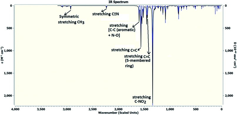
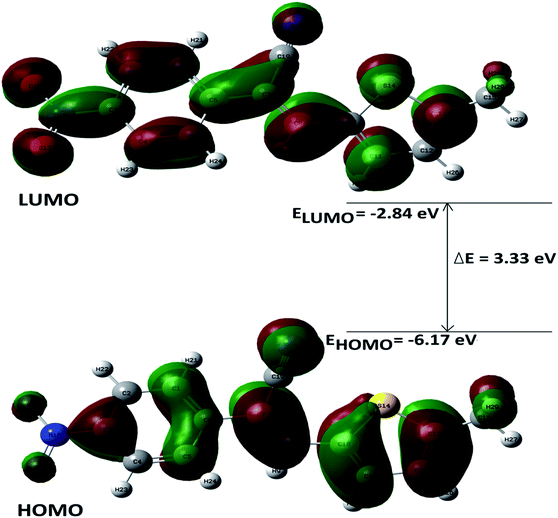
DFT calculations were performed on two isomers (Z and E) of compound 3a using Gaussian 09 software.53 Optimized geometry and IR frequencies of these two isomers were obtained at B3LYP/6-31G(d,p) level of theory. Optimized geometries of (Z)- and (E)-isomer are shown in Fig. 12. The minimum molecular energies of (Z)- and (E)-isomer were found to be −751470.2065 and −751468.5656 kcal mol−1 respectively. It was found that the (Z)-isomer was stabilized by 1.64 kcal mol−1 more than the (E)-isomer. The dipole moment value for the (Z)-isomer was estimated to be 7.86 D and the dipole moment vector pointed towards the five-membered ring. The simulated IR spectrum (scaled by uniform scaling factor of 0.961) along with some assignments for the (Z)-isomer are shown in Fig. 13. The dominant line at 1363 cm−1 corresponded to the stretching frequency of the nitro group. The 1000–1500 cm−1 region represented the combined skeletal vibrations of the molecule, and the lines at 1604 cm−1 and 1615 cm−1 were dominated by the C![[double bond, length as m-dash]](https://www.rsc.org/images/entities/char_e001.gif) C stretching vibration. The CN stretching vibrational mode was observed at 2312 cm−1. The results were nearly in accordance with the experimentally obtained IR spectrum of the molecule. Spatial plots of HOMO and LUMO along with corresponding energy values and HOMO–LUMO gap are illustrated in Fig. 14. The figure depicts localized HOMO and LUMO over the whole molecule. HOMO–LUMO transition showed the charge delocalization within the molecule.
C stretching vibration. The CN stretching vibrational mode was observed at 2312 cm−1. The results were nearly in accordance with the experimentally obtained IR spectrum of the molecule. Spatial plots of HOMO and LUMO along with corresponding energy values and HOMO–LUMO gap are illustrated in Fig. 14. The figure depicts localized HOMO and LUMO over the whole molecule. HOMO–LUMO transition showed the charge delocalization within the molecule.
Conclusion
In summary the present work reports a new, simple, convenient and eco-friendly functionalized MOF-assisted synthesis of (Z)-acrylonitrile derivatives. The products were obtained in excellent yield (90–96%) with high purity. The prominent features of this procedure are mild reaction conditions, operational simplicity, enhanced reaction rates, cleaner reaction profiles and simple experimental and product separation procedures, which make this method attractive. Furthermore, these features will enable this method to find extensive applications in the field of organic synthesis.Experimental section
Synthesis of IRMOF-3
IRMOF-3 was synthesized according to a reported procedure,54 with slight modifications. Aminoterephthalic acid (2 g) and trimethylamine (4.5 mL) were dissolved in 100 mL of DMF to which was added Zn(OAc)2·2H2O (6 g) dissolved in 150 mL of DMF. The reaction mixture was stirred for 2.5 h. The precipitate as obtained was filtered and immersed in DMF (100 mL) and kept overnight. It was then filtered again and immersed in CHCl3 (100 mL, HPLC grade). The solvent was exchanged 3 times over 7 days: after 2 days, 3 days, and 7 days. The bulk of the solvent was decanted; the product was evacuated overnight and activated at 150 °C for 24 h.Synthesis of S-IRMOF-3
To a magnetically stirred mixture of IRMOF-3 (1 g) in CHCl3 (20 mL), chlorosulfonic acid (0.5 mL) was added dropwise at 0 °C. After the addition was complete, the mixture was stirred for 2 h until all HCl was removed from the reaction vessel. The mixture was then filtered, washed with methanol (20 mL) and dried at room temperature to give S-IRMOF-3 as white fine powder.Determination of H+ ion concentration of S-IRMOF-3
The H+ ion concentration of the catalyst was determined by neutralization titration. 100 mg of S-IRMOF-3 was stirred in 20 mL of 0.1 N NaOH solution for 30 min in an Erlenmeyer flask. The excess amount of base was then neutralized by the addition of 0.1 N HCl solution to the equivalence point of titration. The H+ ion concentration was found to be 0.33 meq. g−1.General procedure for the synthesis of acrylonitrile derivatives
To a mixture of substituted aromatic and hetero-aromatic aldehydes (1a–o) (1 mmol) and p-nitrophenylacetonitrile (2) (1 mmol) in ethanol (5 mL) was added S-IRMOF-3 (200 mg). The reaction mixture was refluxed at 90 °C for 30 min. After completion of the reaction, as evident from TLC, the formed solid was filtered and washed with hot methanol to recover the catalyst. The filtrate containing a soluble product was evaporated under reduced pressure to obtain a crude product. The crude product obtained was washed with appropriate solvents, filtered, dried and crystallized from appropriate solvents. The catalyst was reused without a significant reduction of product yield.Conflicts of interest
There are no conflicts to declare.Acknowledgements
The authors would like to acknowledge DRS II (UGC, New Delhi), Department of Physics, AMU, for DFT analysis, University Sophisticated Instrument Facility (USIF), AMU, Aligarh, for SEM-EDX and TEM facilities, NCL Pune for 13C MAS NMR analysis, IIT Madras for TPD-NH3 and SAIF Punjab for providing NMR and mass spectra.References
- L. D. Bonifacio, B. V. Lotsch, D. P. Puzzo, F. Scotognella and G. A. Ozin, Adv. Mater., 2009, 21, 1641–1646 CrossRef CAS.
- H. C. Zhou, J. R. Long and O. M. Yaghi, Chem. Rev., 2012, 8, 673–674 CrossRef PubMed.
- M. Bardosova, M. E. Pemble, I. M. Povey, R. H. Tredgold and D. E. Whitehead, Appl. Phys. Lett., 2006, 89, 093116 CrossRef.
- R. Stine, J. T. Robinson, P. E. Sheehan and C. R. Tamanaha, Adv. Mater., 2010, 22, 5297–5300 CrossRef CAS PubMed.
- (a) G. Férey, Chem. Soc. Rev., 2008, 37, 191–214 RSC; (b) J. R. Long and O. M. Yaghi, Chem. Soc. Rev., 2009, 38, 1213–1214 RSC; (c) T. R. Cook, Y. R. Zheng and P. J. Stang, Chem. Rev., 2012, 113, 734–777 CrossRef PubMed.
- (a) D. Farrusseng, S. Aguado and C. Pinel, Angew. Chem., Int. Ed., 2009, 48, 7502–7513 CrossRef CAS PubMed; (b) J. Lee, O. K. Farha, J. Roberts, K. A. Scheidt, S. T. Nguyen and J. T. Hupp, Chem. Soc. Rev., 2009, 38, 1450–1459 RSC.
- W. Zhu, C. He, X. Wu and C. Duan, Inorg. Chem. Commun., 2014, 39, 83–85 CrossRef CAS.
- F. X. L. I. Xamena, A. Abad, A. Corma and H. Garcia, J. Catal., 2007, 250, 294–298 CrossRef.
- L. T. Nguyen, C. V. Nguyen, G. H. Dang, K. K. Le and N. T. Phan, J. Mol. Catal. A: Chem., 2011, 349, 28–35 CrossRef CAS.
- P. Li, S. Regati, R. J. Butcher, H. D. Arman, Z. Chen, S. Xiang, B. Chen and C. G. Zhao, Tetrahedron Lett., 2011, 52, 6220–6222 CrossRef CAS PubMed.
- A. Dhakshinamoorthy, M. Alvaro and H. Garcia, Adv. Synth. Catal., 2010, 352, 711–717 CrossRef CAS.
- M. Opanasenko, M. Shamzhy, M. Lamač and J. Čejka, Catal. Today, 2013, 204, 94–100 CrossRef CAS.
- S. Gao, N. Zhao, M. Shu and S. Che, Appl. Catal., A, 2010, 388, 196–201 CrossRef CAS.
- M. J. Vitorino, T. Devic, M. Tromp, G. Férey and M. Visseaux, Macromol. Chem. Phys., 2009, 210, 1923–1932 CrossRef CAS.
- G. Férey, Chem. Soc. Rev., 2008, 37, 191–214 RSC.
- (a) J. R. Long and O. M. Yaghi, Chem. Soc. Rev., 2009, 38, 1213–1214 RSC; (b) S. Kitagawa, R. Kitaura and S. I. Noro, Angew. Chem., Int. Ed., 2004, 43, 2334–2375 CrossRef CAS PubMed.
- J. L. Rowsell and O. M. Yaghi, Microporous Mesoporous Mater., 2004, 73, 3–14 CrossRef CAS.
- X. Kang, H. Liu, M. Hou, X. Sun, H. Han, T. Jiang, Z. Zhang and B. Han, Angew. Chem., Int. Ed., 2016, 55, 1080–1084 CrossRef CAS PubMed.
- (a) B. Karimi and D. Zareyee, Tetrahedron Lett., 2005, 46, 4661–4665 CrossRef CAS; (b) B. Karimi and D. Zareyee, Tetrahedron Lett., 2005, 46, 4661–4665 CrossRef CAS; (c) B. Das, K. Venkateswarlu, M. Krishnaiah and H. Holla, Tetrahedron Lett., 2006, 47, 7551–7556 CrossRef CAS; (d) S. Shylesh, S. Sharma, S. P. Mirajkar and A. P. Singh, J. Mol. Catal. A: Chem., 2004, 212, 219–228 CrossRef CAS.
- D. Margolese, J. A. Melero, S. C. Christiansen, B. F. Chmelka and G. D. Stucky, Chem. Mater., 2000, 12, 2448–2459 CrossRef CAS.
- W. Van Rhijn, D. De Vos, B. Sels and W. Bossaert, Chem. Commun., 1998, 3, 317–318 RSC.
- J. G. Shen, R. G. Herman and K. Klier, J. Phys. Chem. B, 2002, 106, 9975–9978 CrossRef CAS.
- R. van Grieken, J. A. Melero and G. Morales, Appl. Catal., A, 2005, 289, 143–152 CrossRef CAS.
- B. Rác, A. Molnar, P. Forgo, M. Mohai and I. Bertóti, J. Mol. Catal. A: Chem., 2006, 244, 46–57 CrossRef.
- J. A. Melero, R. Van Grieken, G. Morales and V. Nuño, Catal. Commun., 2004, 5, 131–136 CrossRef CAS.
- I. K. Mbaraka and B. H. Shanks, J. Am. Oil Chem. Soc., 2006, 83, 79–91 CrossRef CAS.
- A. Carta, P. Sanna, M. Palomba, L. Vargiu, M. La Colla and R. Loddo, Eur. J. Med. Chem., 2002, 37, 891–900 CrossRef CAS PubMed.
- K. M. Dawood, N. M. Elwan, A. A. Farahat and B. F. Abdel-Wahab, Synthesis, J. Heterocycl. Chem., 2010, 47, 243–267 CAS.
- A. Carta, M. Palomba, G. Boatto, B. Busonera, M. Murreddu and R. Loddo, Il Farmaco, 2004, 59, 637–644 CrossRef CAS PubMed.
- J. Quiroga, D. Cobo, B. Insuasty, R. Abonía, M. Nogueras, J. Cobo, Y. Vasquez, M. Gupta, M. Derita and S. Zacchino, Arch. Pharm., 2007, 340, 603–606 CrossRef CAS PubMed.
- M. Hranjec, G. Pavlović, M. Marjanović, M. Kralj and G. Karminski-Zamola, Eur. J. Med. Chem., 2010, 45, 2405–2417 CrossRef CAS PubMed.
- F. Sączewski, A. Stencel, A. M. Bieńczak, K. A. Langowska, M. Michaelis, W. Werel, R. Hałasa, P. Reszka and P. J. Bednarski, Eur. J. Med. Chem., 2008, 43, 1847–1857 CrossRef PubMed.
- P. Sanna, A. Carta and M. E. R. Nikookar, Eur. J. Med. Chem., 2000, 35, 535–543 CrossRef CAS PubMed.
- H. M. F. Madkour, Chem. Pap., 2002, 56, 313 CAS.
- W. Kuzmierkiewicz, H. Foks and M. Baranowski, Sci. Pharm., 1985, 53, 133–138 CAS.
- P. Sanna, A. Carta, L. Gherardini and M. E. R. Nikookar, Il Farmaco, 2002, 57, 79–87 CrossRef CAS.
- M. Parveen, A. M. Malla, M. Alam, M. Ahmad and S. Rafiq, New J. Chem., 2014, 38, 1655–1667 RSC.
- L. Quattara, M. Debaert and R. Cavier, Farmaco, Ed. Sci., 1987, 42, 383–396 CAS.
- A. Repicky, S. Jantova and L. Cipak, Cancer Lett., 2009, 277, 55–63 CrossRef CAS PubMed.
- L. W. Yi, X. Q. Hai, M. Y. Xiang, L. Y. Min, D. N. Li and G. D. Peng, J. Org. Chem., 2001, 625, 128–131 CrossRef.
- S. El-Tamany, F. W. Raulfs and H. Hopf, Angew. Chem., Int. Ed. Engl., 1983, 22, 633–634 CrossRef.
- J. Masllorens, M. Moreno-Mañas, A. Pla-Quintana, R. Pleixats and A. Roglans, Synthesis, 2002, 1903–1911 CAS.
- G. Thirupathi, M. Venkatanarayana, P. K. Dubey and K. Y. Bharathi, Der Pharma Chem., 2012, 4, 1897–1901 CAS.
- (a) R. A. Rather and Z. N. Siddiqui, J. Org. Chem., 2018, 868, 164–174 CrossRef CAS; (b) S. Siddiqui, M. U. Khan and Z. N. Siddiqui, ACS Sustainable Chem. Eng., 2017, 5(9), 7932–7941 CrossRef CAS; (c) M. U. Khan and Z. N. Siddiqui, ACS Omega, 2018, 3(8), 10357–10364 CrossRef CAS; (d) S. Siddiqui and Z. N. Siddiqui, Catal. Lett., 2018, 148(12), 3628–3645 CrossRef CAS; (e) M. U. Khan and Z. N. Siddiqui, ACS Omega, 2019, 4, 7586–7595 CrossRef CAS.
- M. Zhao, K. Deng, L. He, Y. Liu, G. Li, H. Zhao and Z. Tang, J. Am. Chem. Soc., 2014, 136, 1738–1741 CrossRef CAS PubMed.
- (a) L. Lili, Z. Xin, G. Jinsen and X. Chunming, Green Chem., 2012, 14, 1710–1720 RSC; (b) J. A. Greathouse and M. D. Allendorf, J. Phys. Chem. C, 2008, 112, 5795–5802 CrossRef CAS.
- H. Sun, H. Su, X. Ma, P. Zhang, X. Zhang, X. Dai, J. Gao, C. Chen and S. G. Sun, Electrochim. Acta, 2016, 205, 53–61 CrossRef CAS.
- R. M. Abdelhameed, L. D. Carlos, A. M. Silva and J. Rocha, Chem. Commun., 2013, 49, 5019–5021 RSC.
- D. Elhamifar, M. Nasr-Esfahani, B. Karimi, R. Moshkelgosha and A. Shábani, ChemCatChem, 2014, 6, 2593–2599 CrossRef CAS.
- N. T. Phan, T. T. Nguyen, Q. H. Luu and L. T. Nguyen, J. Mol. Catal. A: Chem., 2012, 363, 178–185 CrossRef.
- E. Rahmani and M. Rahmani, Ind. Eng. Chem. Res., 2017, 57, 169–178 CrossRef.
- T. C. Su, Z. Fang, F. Zhang, J. Luo and X. K. Li, Sci. Rep., 2015, 5, 17538 CrossRef PubMed.
- M. J. Frisch, G. W. Trucks, H. B. Schlegel, G. E. Scuseria, M. A. Robb, J. R. Cheeseman, G. Scalmani, V. Barone, B. Mennucci and G. A. Petersson, et al., Gaussian 09, Gaussian. Inc., Wallingford CT, 2009, vol. 121, pp. 150–166 Search PubMed.
- L. M. Huang, H. T. Wang, J. X. Chen, Z. B. Wang, J. Y. Sun, D. Y. Zhao and Y. S. Yan, Microporous Mesoporous Mater., 2003, 58, 105 CrossRef CAS.
Footnote |
| † Electronic supplementary information (ESI) available. See DOI: 10.1039/c9ra01012b |
| This journal is © The Royal Society of Chemistry 2019 |


