
 Open Access Article
 This Open Access Article is licensed under a Creative Commons Attribution-Non Commercial 3.0 Unported Licence
Recovery of cobalt from dilute aqueous solutions using activated carbon–alginate composite spheres impregnated with Cyanex 272†
Stijn Van Roosendael ab,
Bieke Onghenaab,
Joris Roosenab,
Bart Michielsenbc,
Kenny Wynsc,
Steven Mullensc and
Koen Binnemans*a
ab,
Bieke Onghenaab,
Joris Roosenab,
Bart Michielsenbc,
Kenny Wynsc,
Steven Mullensc and
Koen Binnemans*a
aKU Leuven, Department of Chemistry, Celestijnenlaan 200F, P. O. box 2404, BE-3001 Heverlee, Belgium. E-mail: koen.binnemans@kuleuven.be; Tel: +32 16 32 74 46
bSIM vzw, Technologiepark 935, BE-9052 Zwijnaarde, Belgium
cVITO, Unit Sustainable Materials Management, Boeretang 200, BE-2400 Mol, Belgium
First published on 14th June 2019
Abstract
A novel adsorbent was designed for selective recovery of cobalt(II) from synthetic binary cobalt(II)–nickel(II) and cobalt(II)–manganese(II) solutions, a synthetic multi-element solution and a real aqueous waste stream from the petrochemical sector. The adsorbent consisted of shaped activated carbon–alginate spheres impregnated with Cyanex 272. The synthesis was followed by characterisation using SEM, infrared spectroscopy, BET analysis and elemental analysis. Good selectivity for cobalt(II) over nickel(II) could be achieved during adsorption, while this was not the case for cobalt(II) over manganese(II). Cobalt(II) and manganese(II) were therefore fully adsorbed and stripped using a dilute sulphuric acid solution. The adsorbent was shown to be reusable in a column setup. Finally, the adsorbent material was used for the purification of a real aqueous waste stream from the petrochemical sector.
1. Introduction
During chemical and metallurgical processing, large volumes of side streams are generated along with the production of sellable end products. Although these side streams often contain valuable metals, the streams are generally not reused in production processes, but are discarded instead. This decision is often based on various reasons including the toxicity of the side streams or the depletion of the metal content.1 Generally, these side streams are immobilised and stockpiled into a landfill. In case of non-hazardous streams and considering the discharge limits, release into the environment is preferred when this possibility arises on the industrial site, e.g. when aqueous side streams can be discharged in a nearby waterway. Both cases inevitably count for significant losses of valuable elements, such as cobalt. Cobalt is commonly found in nickel laterite ores, sulphidic ores or in copper–cobalt oxide ores and is therefore mainly produced as a by-product of the nickel and copper industry.2–4 It is mainly used as alloying metal,5 blue colourant,5–7 catalyst8–10 or as a component of (rechargeable) batteries, with a typical cobalt content of 5–20 wt%.11–14 Due to the rapidly growing rechargeable battery industry, mainly for its use in electrical vehicles, the demand for cobalt is increasing at a fast pace.14–16 To meet this high demand in the future, cobalt recycling technologies must be further explored and/or improved. An additional benefit of recovering cobalt is that possible environmental pollution is avoided, thus minimising exposure of this toxic element that is known to induce various adverse effects on the human health.11,17,18 A variety of methods have already been applied to recover cobalt, many of them based on cobalt recovery from waste lithium ion batteries (LIBs)14,19–22 or nickel metal hydride (NiMH) batteries.12,23–25 The methods for the recovery of cobalt from aqueous solutions vary between aqueous two-phase system extraction,12,26 electrowinning,27,28 cementation,29,30 solvent extraction,24,31 solvent extraction followed by electrowinning,32–35 solvent extraction followed by precipitation23,25,36 or precipitation as such.21,22The recovery of cobalt from aqueous solutions has also been performed using various solid-phase extraction systems, including solid adsorbent materials based on activated carbon (AC).37–40 AC has many beneficial properties facilitating their impregnation, such as a good chemical stability and high surface area. Most AC materials exist as a powder, resulting in a low hydraulic conductivity. This makes them ill-suited for packed bed applications and it also complicates the separation.41–43 A well-known method to obtain monodisperse spheres with a good hydraulic conductivity of AC powders is by coagulation with alginate (ALG).44 Alginate easily forms stable and irreversible hydrogels by crosslinking with multivalent ions such as calcium(II). It forms a so-called egg-box structure that originates from the specific coordination of multivalent ions with the guluronate blocks.41–43,45–60 AC–calcium alginate composite (AC–ALG) spheres were already described in literature with applications ranging from dye removal46,51,54,55,57 over removal of organics47–50,58,59 to (heavy) metal removal.49,50,52,53,56 Even magnetic AC–ALG spheres have been designed to allow easy recovery after reaction.51,57,59 AC–ALG spheres can be impregnated using various organic extractants to improve metal recovery and selectivity, which, to the best of our knowledge, has not been studied before for the recovery of cobalt. Cyanex 272, shown in Fig. 1, is a suitable candidate for cobalt recovery since it was developed specifically for the solvent extraction of cobalt. It proved to be very selective for cobalt over nickel extraction at pH 5–6.15,61 However, Cyanex 272 is not suitable for the selective separation of cobalt from mixed cobalt(II)–manganese(II) solutions.15,61 Cyanex 301 and Cyanex 302 are preferred for cobalt separation from manganese-containing solutions, but these extractants are not stable and were therefore not considered in this paper.62,63 The developed material would be similar to the commercially available Lewatit® TP 272, which is also a Cyanex 272 impregnated resin.64 In contrast to the polystyrene-based Lewatit TP 272, which is manufactured from fossil fuels, AC–ALG is a resin derived from renewable sources.
 | ||
| Fig. 1 Chemical structure of the extractant Cyanex 272. | ||
In this paper, AC powder was shaped into porous, hybrid AC–ALG spheres. The spheres were impregnated with Cyanex 272 and applied for the recovery of cobalt(II) from (synthetic) binary cobalt(II)–nickel(II) and cobalt(II)–manganese(II) aqueous solutions in batch mode. The system was also applied for the purification of a real waste stream in column mode.
2. Experimental
2.1. Chemicals and materials
Copper(II) sulphate pentahydrate (≥98.0%) and acetone (>99.5%) were purchased from Sigma-Aldrich (Overijse, Belgium). Sulphuric acid (>95%), glacial acetic acid (≥99.7%), sodium acetate trihydrate (99.0–101.0%) and sodium hydroxide (99.25%, pearls) were ordered from Fisher Scientific (Loughborough, UK). Iron(III) sulphate hydrate (≥21% Fe), calcium chloride dihydrate (100.6%), 2-propanol (98%) were purchased from VWR Chemicals (Leuven, Belgium). Nickel(II) sulphate hexahydrate (>99%) was purchased from UCB (Brussels, Belgium). Cobalt(II) sulphate heptahydrate (>99%), zinc(II) sulphate monohydrate (99%), manganese(II) sulphate monohydrate (>99%) and petroleum ether (pure, boiling range ca. 180–280 °C) were purchased from Acros Organics (Geel, Belgium). Sodium hydrosulphide (95%) was purchased from Janssen Chimica (Geel, Belgium). Cyanex 272® was obtained from Cytec Canada Inc. (Niagara Falls, Ontario, Canada). 1000 μg mL−1 ICP standard solutions were purchased from Chem-Lab nv (Zedelgem, Belgium). Sodium alginate BR-W was obtained from Brace GmbH (Karlstein am Main, Germany). As activated carbon source, Norit® SX-1G was used, which is an acid-washed and steam-activated carbon from NORIT NV (Amersfoort, the Netherlands).All chemicals were used as received without any further purification, unless stated otherwise. Aqueous solutions were prepared using 18.2 MΩ cm ultrapure water, produced by a Milli-Q® Reference system. The real waste solution used in this manuscript resulted from a purification step in the production of terephthalic acid and contained 10.0 mg L−1 cobalt(II), 6.2 mg L−1 manganese(II) and some organic compounds.
2.2. Equipment and analysis
Prior to the AC–ALG particle formation, the AC powder was milled in a planetary ball mill (PM 100 Retsch) using tungsten carbide milling balls of 20 mm diameter and tungsten carbide milling pots. The AC–ALG composite spheres were shaped by making use of the Spheronisator M (Brace GmbH, Alzenau, Germany). The particle size was determined via a combination of light diffraction and a dynamic image analysis system (Microtrac S3500 equipped with a PartAn SI analyser attachment). The PartAn SI analyser is a photo-optical image analyser in a modular footprint that provides in-depth shape analysis of particles suspended in fluids. It comprises a single white-light source, camera, strobe control and CCD photo detector array. Each sample was subjected to ultrasound for 30 s and measured for 30 s at 40% of the maximum flow. The rheology of the suspensions was measured with a HAAKE MARS rheometer (Germany, Z43 DIN 53018 cup and Z41 DIN 53018 rotor). Rheology curves were provided in a shear rate interval between 0.01 and 1000 s−1 and data points were collected while decreasing the shear rate. Viscosity screening in the shear rate interval took 5 min. The temperature was controlled by a thermostatic bath set at 25 °C. The outer surface of the microspheres was investigated using a thermal field emission scanning electron microscope (FEGSEM) of the type Nova Nano SEM 450 (FEI) and was characterised at 5 kV. Fourier Transform Infrared (FTIR) spectra were recorded between 4000 and 400 cm−1 on a Bruker Vertex 70 spectrometer equipped with a Platinum ATR module. CHN elemental analyses were performed using a Thermo Scientific Interscience Flash 2000 CHN(SO) elemental analyser. A Quantachrome Instruments NOVA 2000e volumetric adsorption analyser was used to record nitrogen adsorption–desorption isotherms at 77 K. From these, the specific surface area of the impregnated material, its pore volume and pore size distribution were calculated, based on the Brunauer–Emmet–Teller (BET) method and the Barrett–Joyner–Halenda (BJH) method, respectively. Prior to the measurements, the activated carbon material was degassed under vacuum for 24 h at 22 °C. A Mettler-Toledo pH meter with a Hamilton Slimtrode pH electrode was used for pH measurements. The metal content of the aqueous solutions was measured using a PerkinElmer Optima 8300 Inductively Coupled Plasma-Optical Emission Spectrometer (ICP-OES) equipped with an axial/radial dual plasma view. Appropriate dilutions were made with 2 wt% nitric acid. Calibration curves, based on five standard solutions of known concentration (0.02, 0.10, 0.25, 1.00 and 5.00 mg L−1), were constructed for all elements in the analysis. Scandium (5 mg L−1) was added as an internal standard to each calibration and sample solution. Quality control samples were measured before and after measuring the sample series. Reported wavelengths and view mode (AX/RAD) are summarised in the ESI (Table S1†). All ICP-OES spectra were measured in triplicate. A Thermo Scientific MaxQ 2000 orbital shaker was used for all batch experiments (adsorption, washing and stripping) at 170 rpm. Column experiments were performed using Bio-Rad glass columns with a 0.7 cm inner diameter and 30 cm length, an Ismatec IPC high-precision multichannel peristaltic pump (operating at 0.5 mL min−1 during sample loading and equilibration and operating at 0.2 mL min−1 during stripping and scrubbing) and a Spectra/Chrom CF-2 fraction collector. The column was packed with 1.50 g of the adsorbent particles, resulting in a bed volume of 12.7 mL. The technological flowsheet was drawn using the web-based application draw.io and the graphical abstract and chemical structure of Cyanex 272 was drawn using ChemDraw Prime 17.1. All experiments were performed at room temperature.2.3. Shaping of the AC–ALG spheres
The commercial AC powder used in this study had a broad size distribution with particles up to 300 μm. Particles of this size would clog the nozzle rapidly during the composite droplet generation and would result in inhomogeneous particle packing. To this end, 40 g of the AC powder was milled in a planetary ball mill for 20 min at 400 rpm. Subsequently, the milled AC powder was dispersed in ultrapure water. Then, a pre-dissolved sodium alginate solution (4 wt% in water) and extra ultrapure water were added to prepare the feeding suspension. The final composition amounted to 10 wt% AC, 1 wt% ALG and 89 wt% water.First, the feeding suspension was loaded in the feed tank, which contained a magnetic stirrer to prevent powder sedimentation during the process. By applying a constant pressure (300 mbar overpressure) on the feed tank, a laminar flow was obtained through a 300 μm nozzle. The flow was broken up in uniform droplets by applying a vibration with a defined frequency of 500 Hz and an amplitude of 2500 mV. The droplets were collected and solidified in the coagulation bath containing the reacting salt to establish an ionotropic gelation. The coagulation bath was made by dissolving 0.22 mol L−1 calcium chloride dihydrate in deionised water. Isopropyl alcohol was sprayed on top of the coagulation bath to reduce its surface tension. The obtained solid microspheres were kept in the coagulation bath overnight to complete the solidification. Afterwards, the microspheres were thoroughly washed with ultrapure water to remove the excess of ions after which they were washed with isopropyl alcohol to reduce the capillary pressure during drying. Finally, the samples were dried overnight at 80 °C.
2.4. Impregnation of the AC–ALG spheres
Physical impregnation was performed by adding Cyanex 272 (100 mL) and acetone (200 mL) to the shaped and dried AC–ALG spheres (10 g) and shaking the mixture for 68 h at 50 °C. After cooling down the mixture, the solution was decanted and the remaining spheres were rinsed with ultrapure water (200 mL) by shaking for 1 h. The impregnated and washed spheres, further referred to as AC–ALG-C272, were dried to open air for 48 h at 50 °C. The AC–ALG-C272 spheres were characterised by CHN elemental analysis, infrared spectroscopy and nitrogen adsorption–desorption isotherms for the determination of the pore size distribution, the specific surface area and the pore volume. The amount of impregnated Cyanex 272 was determined by contacting the AC–ALG-C272 particles (100 mg) with petroleum ether (5 mL) for 2 h in a closed vial, thereby diluting the impregnated Cyanex 272 and homogenising the organic phase. The phosphorus content of the organic phase was then determined by ICP-OES.2.5. Adsorption parameter optimisation
Metal-ion stock solutions were prepared by dissolving the sulphate metal salts in ultrapure water. A small aliquot of concentrated H2SO4 was added to adjust the pH to prevent precipitation by hydrolysis. Before the adsorption experiments, the pH of the starting solutions was adjusted in advance by combining with a 0.25 mol L−1 acetate buffer in a ratio depending on the desired pH of the solution, which allowed to control the pH during the adsorption experiment. Unless stated otherwise, adsorption experiments proceeded as follows: in closed glass vials, dry AC–ALG-C272 spheres (50 mg) were added to 10 mL of an aqueous solution containing 0.5 mmol L−1 of the desired metal cations; the adsorption experiments were maintained for 1 h by shaking the solutions at 170 rpm and room temperature; after adsorption, the AC–ALG-C272 spheres were separated from the liquid by means of a 0.45 μm syringe filter.Adsorption efficiencies (% A) were calculated by measuring the metal concentration of the aqueous solution before and after the adsorption experiment, using eqn (1):
 | (1) |
To quantify the ability of a certain system to separate Co(II) from another metal (M), the separation factor (α) was introduced, calculated using eqn (2):
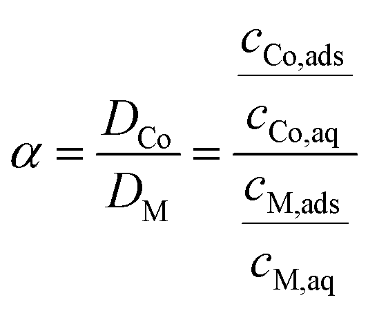 | (2) |
To demonstrate the benefit of using the developed system, the non-impregnated AC–ALG particles (50 mg) were also used to remove the metal ions out of the aqueous phase using the optimised parameter setup. This experiment was performed both on the binary cobalt(II)–nickel(II) and cobalt(II)–manganese(II) system after which the results were compared with the impregnated AC–ALG-C272 system.
2.6. Stripping parameter optimisation
Stripping tests were performed by first loading the AC–ALG-C272 spheres using the optimised adsorption procedure: adding an acetate buffer (5 mL, 0.5 mol L−1 buffer capacity) and the AC–ALG-C272 spheres (50 mg) to a metal sulphate solution (5 mL, 1 mmol L−1 per metal) of pH 5 (except for the multi-element solutions, where stock solutions of pH 2 were used to prevent hydrolysis) and shaking for 1 h (Subsection 3.3). The pH of the mixture before adsorption was 6.25. After separating the loaded spheres from the aqueous phase using a syringe and needle, washing the spheres for 1 h using ultrapure water (10 mL) and separating the spheres from the washing solution, the loaded spheres were contacted with a sulphuric acid stripping solution of variable concentration (0.1–5 × 10⁻³ mol L−1) and with a variable volume (2–15 mL) for a certain time (1 min to 6 h). The stripping efficiency was calculated using eqn (3):
 | (3) |
2.7. Column experiment: case study
The performance of the AC–ALG-C272 spheres was also tested on an actual process stream. A first column experiment was performed by (in chronological order): equilibrating the packed column with a diluted H2SO4 solution (15 mL, pH 6.25, step 1), loading the column with the actual waste stream (15 mL, step 2), equilibrating the column again using a diluted H2SO4 solution (15 mL, pH 6.25, step 3), stripping the adsorbent using 0.2 mmol L−1 H2SO4 solution (15 mL, step 4) and 0.25 mmol L−1 H2SO4 solution (15 mL, step 5), scrubbing the remaining metal ions using a 1 mmol L−1 H2SO4 solution (15 mL, step 6) and finally equilibrating the material again using a diluted H2SO4 solution (5 mL, pH 6.25, step 7). The solutions were added to the column in steps of 5 mL. To fully remove cobalt(II) and manganese(II) from the waste solution, an additional and similar column experiment was performed in which 30 mL of the actual waste stream was loaded onto the column and the stripping and scrubbing steps were combined into one step using a 0.01 mol L−1 H2SO4 solution (30 mL).2.8. Reusability assessment
The reusability of the AC–ALG-C272 particles was tested by performing five subsequent (optimised) adsorption–washing–stripping–washing cycles from a binary cobalt–nickel solution using the batch setup. The reusability of the particles was also tested in a column setup. The morphology of the AC–ALG-C272 particles before and after reaction was studied using SEM analysis to visualise the effect of a full adsorption and desorption cycle on the particle structure.3. Results and discussion
3.1. Shaping of the AC–ALG spheres
The apparatus for making the AC–ALG composite spheres was set up as presented in Fig. 2. The particle size distributions of the AC powder before and after milling are shown in Fig. S1.† After milling, the largest particle size was reduced to below 30 μm, with a median particle diameter (d50) of 3 μm. The resulting viscosity of the feeding suspension is shown in Fig. S2.† The suspension exhibits clear shear thinning behaviour with a high viscosity at low shear rate. However, at the shear rates encountered at the nozzle (around 60 s−1) the viscosity values are around 200 mPa s, which is sufficiently low to form a laminar flow and shape microspheres, as indicated by Pype et al.65 | ||
| Fig. 2 Schematic representation of the vibrational droplet coagulation setup. (1) Feed vessel with magnetic stirrer; (2) air pressure controller; (3) vibration generator with frequency and amplitude control; (4) nozzle; (5) stroboscopic lamp; (6) coagulation bath. | ||
First, the process parameters such as the frequency and the amplitude for the vibrational droplet coagulation procedure were optimised to obtain a stable jet, similar to previous studies.45,65 The interruption of the laminar jet was visualised using a stroboscopic light source. When the stroboscope flashes in phase with the vibrating nozzle, the apparent continuous stream can be detected by the eye as distinct droplets. The instrument parameters were optimised in such a way that droplets were observed at a stable position without the observation of smaller satellite droplets in between the main droplets.
The dried microspheres were investigated by photo-optical dynamic image analysis to qualitatively confirm the spherical shape, monomodal size distribution and micrometer size range. The data are collected in Table 1. The average area equivalent diameter Da can be calculated from this data as follows:
 | (4) |
| Da (μm) | L (μm) | W (μm) | W/L ratio | Sphericity | |
|---|---|---|---|---|---|
| d10 | 498 | 537 | 456 | 0.79 | 0.86 |
| d50 | 521 | 572 | 484 | 0.86 | 0.95 |
| d90 | 549 | 595 | 520 | 0.92 | 0.97 |
| Average | 524 (30) | 569 (23) | 485 (26) | 0.85 (6) | 0.93 (4) |
For the dried AC–ALG spheres, the average equivalent diameter was 524 ± 30 μm, as determined from 672 spheres. The d90/d10 ratio is a measure for the uniformity of the shaped microspheres. For the dried AC–ALG spheres, the d90/d10 ratio was determined to be 1.10, indicating that the particles were quite monomodal and the size distribution quite narrow. As this value for the diameter is calculated from the area, it gives no information about the shape of the spheres. To this end, the Feret length L and width W were determined, which relate to the maximal and minimal Feret diameter, respectively. The Feret diameter is defined as the distance between two parallel tangential lines of a circle.66–68 A W/L ratio close to 1 indicates a perfect circle or sphere. For the AC–ALG spheres, an average value of 0.85 ± 6 was found. In Fig. 3, the Feret ratio distribution is plotted against the sphere diameter distribution. No decrease in W/L ratio is observed in correlation to the microsphere size.
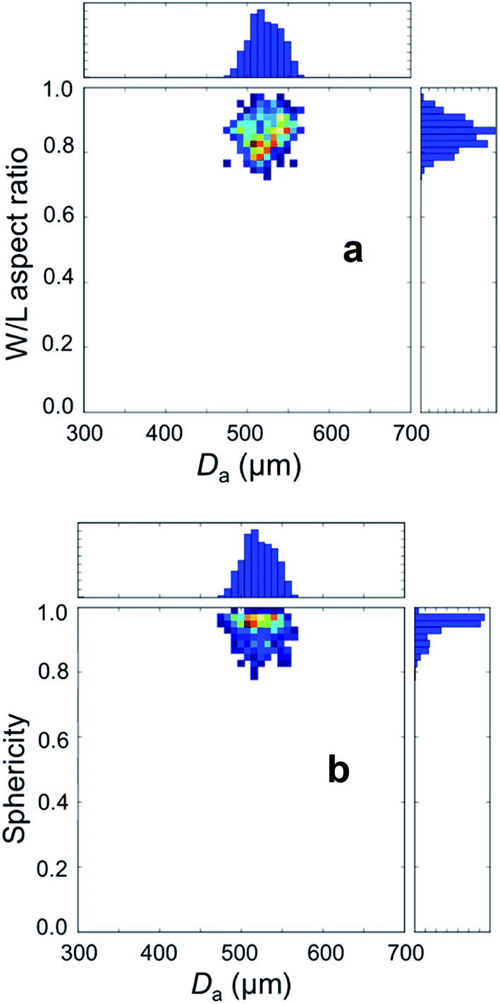 | ||
| Fig. 3 Size and shape parameters of the AC–ALG microspheres determined using particle image analysis. The distribution of the W/L aspect ratio (plot a) and sphericity (plot b) is plotted against the area equivalent diameter (Da) distribution. The data were normalised by the amount of measured particles. | ||
Another parameter which can be easily calculated is the sphericity. The sphericity is defined as follows:
 | (5) |
Sphericity of the AC–ALG spheres was found to be quite high, with a value of 0.93 ± 0.04. The sphericity distribution is plotted in Fig. 3 as well and is quite high at all microsphere sizes.
SEM images of a representative AC–ALG sphere and its outer surface are shown in Fig. 4. The shape of the sphere appeared to be slightly oval, which is in good correlation with the high sphericity value and somewhat lower W/L ratio. The oval shape most likely originates from the flattening of the droplet on impact with the coagulation bath. Due to the rapid coagulation, the droplet does not get sufficient time to go back to an ideal sphere (which has the lowest surface tension).
 | ||
| Fig. 4 SEM images of the dried AC–ALG spheres at different magnifications: 120× (a), 500× (b) and 5000× (c). | ||
3.2. Characterisation of the impregnated AC–ALG spheres
The AC–ALG-C272 spheres were first characterised using FTIR spectroscopy. The FTIR spectrum is shown in Fig. S3.† The characteristic peaks of the FTIR spectrum of the AC–ALG-C272 spheres were: 3362 cm−1, 2352 cm−1 and 1711 cm−1 (O–H stretches); 2950 cm−1, 2899 cm−1 and 2867 cm−1 (C–H stretches); 1464 cm−1, 1362 cm−1, 809 cm−1 and 648 cm−1 (C–H bends); 1392 cm−1 (P–C stretch); 1153 cm−1 (P![[double bond, length as m-dash]](https://www.rsc.org/images/entities/char_e001.gif) O stretch); 1037 cm−1, 937 cm−1, 916 cm−1 and 900 cm−1 (P–O stretches). The presence of the phosphor vibrations confirm that the physical impregnation of Cyanex 272 on the spheres was successful. Further evidence for the successful impregnation was provided by CHN elemental analysis (Table 2). By measuring the carbon, hydrogen and nitrogen content of the AC–ALG-C272 spheres and comparing it with its two starting products, namely the AC–ALG spheres and Cyanex 272, it was concluded that the impregnation of the AC–ALG spheres succeeded well. Based on the carbon content of the different products, a conclusion was made that the impregnated spheres consisted of 19.3 wt% Cyanex 272. Since the hydrogen mass fraction changed to a larger extent than the carbon mass fraction when impregnating the AC–ALG spheres, it was also concluded that not only pure Cyanex 272 was impregnated, but that probably also traces of water remained in the pores, which led to a larger change in hydrogen mass fraction.
O stretch); 1037 cm−1, 937 cm−1, 916 cm−1 and 900 cm−1 (P–O stretches). The presence of the phosphor vibrations confirm that the physical impregnation of Cyanex 272 on the spheres was successful. Further evidence for the successful impregnation was provided by CHN elemental analysis (Table 2). By measuring the carbon, hydrogen and nitrogen content of the AC–ALG-C272 spheres and comparing it with its two starting products, namely the AC–ALG spheres and Cyanex 272, it was concluded that the impregnation of the AC–ALG spheres succeeded well. Based on the carbon content of the different products, a conclusion was made that the impregnated spheres consisted of 19.3 wt% Cyanex 272. Since the hydrogen mass fraction changed to a larger extent than the carbon mass fraction when impregnating the AC–ALG spheres, it was also concluded that not only pure Cyanex 272 was impregnated, but that probably also traces of water remained in the pores, which led to a larger change in hydrogen mass fraction.
| AC–ALG spheres | Cyanex 272 | AC–ALG-C272 spheres | |
|---|---|---|---|
| C (wt%) | 78.7 ± 3.4 | 67.8 ± 0.7 | 76.6 ± 1.6 |
| H (wt%) | 0.9 ± 0.1 | 12.0 ± 0.2 | 6.0 ± 0.3 |
| N (wt%) | 0.0 ± 0.0 | 0.0 ± 0.0 | 0.0 ± 0.0 |
To obtain a more accurate result, the AC–ALG-C272 particles were also contacted with petroleum ether to dilute the impregnated Cyanex 272 and measure the phosphorus concentration of the organic phase. A phosphorus concentration of 868 mg L−1 was measured, which corresponds to a Cyanex 272 content of 30.9 wt%. As expected, this value is higher compared to the value obtained with the CHN analysis as the water content has no influence on the result.
Nitrogen physisorption measurements were performed to study both the inner and outer surface of the AC–ALG-C272 spheres. The adsorption–desorption isotherms are shown in Fig. 5. AC spheres can either be microporous, mesoporous or a combination of both, as indicated in multiple literature reports.69,70 For both the non-impregnated AC–ALG spheres and the impregnated AC–ALG-C272 spheres, a type IV isotherm was recognised with a hysteresis loop of type H4. This type of isotherm is typical for mesoporous materials with slit-like pores.71 This means that capillary condensation of the nitrogen gas in the pores of the solid occurs. The volume of adsorbed N2 drastically decreased after impregnation of the AC–ALG with Cyanex 272, which means that the pores are nearly completely filled with Cyanex 272. The pores are, however, not completely filled as the hysteresis loop type IV remains the same. The total pore volume of the AC–ALG-C272 spheres (0.026 cm3 g−1) is considerably smaller than the total pore volume of the AC–ALG spheres (0.575 cm3 g−1), while at the same time the average pore radius of the AC–ALG-C272 spheres (111.7 nm) is almost twice as big as the AC–ALG spheres (74.1 nm). This could suggest that Cyanex 272 is only deposited on the surface of the AC–ALG spheres (both inner and outer surface), leading to a complete filling of the smallest pores and only partial filling of the bigger pores. The area–volume data derived from the nitrogen adsorption–desorption isotherms also indicated that the specific surface area of the spheres drastically decreased by impregnation, from 879 m2 g−1 to 9 m2 g−1. This is again another indication of the successful impregnation.
 | ||
| Fig. 5 N2 adsorption and desorption isotherms of AC–ALG and AC–ALG-C272. | ||
3.3. Adsorption parameter optimisation
The first experiments were conducted using single-element cobalt(II) solutions in order to study the adsorption behaviour without the influence of other metal cations. The metal extraction mechanism by Cyanex 272 is most likely a cation-exchange mechanism, based on the results of similar systems as reported in the literature.61,72–74 The influence of the pH on the cobalt(II) adsorption was studied first since the pH is considered an important parameter when using the acidic Cyanex 272 extractant. The pH of the starting solutions was adjusted using an acetate buffer in the appropriate ratio. Without the addition of the buffer, the pH would significantly drop as the Cyanex 272 extractant releases its protons upon adsorption of metal ions, resulting in an ineffective adsorption system. The results are shown in Fig. 6. As expected, increasing the pH resulted in an increase in cobalt(II) adsorption, resulting from the deprotonation of the acidic Cyanex 272 extractant. To obtain reasonable cobalt(II) adsorption efficiencies, pH values of 5.5 or higher were needed to be applied.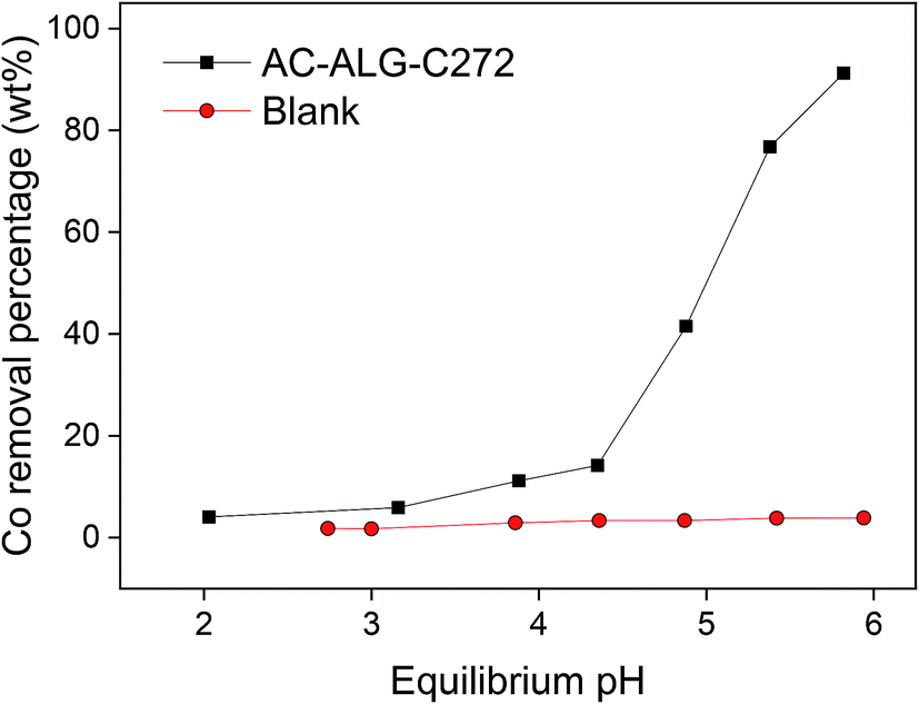 | ||
| Fig. 6 pH influence on the cobalt(II) removal (adsorption) by AC–ALG-C272 (10 mL solution, 0.42 mmol L−1 cobalt(II), 0.25 mol L−1 acetate buffer, 50 mg AC–ALG-C272, 4 h adsorption, pH 2–6). | ||
The second parameter which was studied, was the influence of the adsorbent mass on the cobalt(II) adsorption efficiency, of which the results are shown in Fig. 7. It was observed that by increasing the amount of AC–ALG-C272, the cobalt(II) adsorption efficiency increased. An adsorbent amount of 50 mg was needed to obtain maximum cobalt(II) recovery. Although the use of the acetate buffer already avoided large pH changes during adsorption, it was observed that the equilibrium pH still decreased slightly with increasing amount of adsorbent. By increasing the amount of adsorbent, the amount of acidic Cyanex 272 extractant in contact with the solution increased, thus releasing more protons into the solution. The observed pH changes can be explained by the fact that the adsorption experiments were performed at a pH 6–7, which is higher than the optimal pH range of the acetate buffer (pKa 4.75).75,76 Furthermore, at a pH close to neutral, i.e. pH 7, small changes in proton concentrations have large impact on the pH values due to its logarithmic scale.
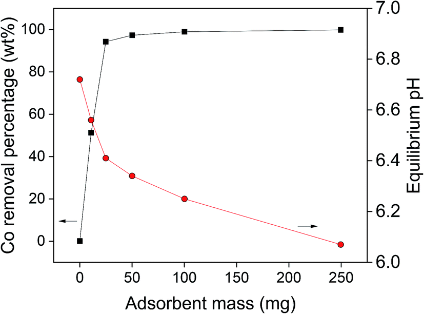 | ||
| Fig. 7 Influence of the amount of AC–ALG-C272 on the cobalt(II) adsorption (10 mL solution, 0.40 mmol L−1 cobalt(II), 0.25 mol L−1 acetate buffer, 0–250 mg AC–ALG-C272, 4 h adsorption, initial pH 6.67). | ||
From the data obtained in Fig. 7, also the adsorption amount can be calculated using eqn (6):
 | (6) |
The selectivity of AC–ALG-C272 towards cobalt(II) over other transition metals was determined by studying the adsorption from multi-element solutions. First, two equimolar binary solutions were considered: cobalt(II)–nickel(II) and cobalt(II)–manganese(II) solutions. The two most straightforward parameters to optimise the selectivity for cobalt(II) are the pH of the solution and the adsorption rate. The influence of the pH on the cobalt(II) adsorption for the cobalt(II)–nickel(II) and cobalt(II)–manganese(II) mixtures is shown in Fig. 8. By increasing the pH, both the cobalt adsorption efficiency and the cobalt(II)–nickel(II) separation factor increased. A high cobalt(II) adsorption efficiency, together with good separation factors, was achieved for pH values of 5.75 or higher, which is similar to the optimal conditions obtained for the single-element Co(II) solution (Fig. 6). However, Fig. 8 clearly indicates that manganese(II) is preferentially adsorbed compared to cobalt(II), which was also expected since Cyanex 272 has been reported to be more selective for manganese(II) over cobalt(II) in liquid–liquid extraction.61 Another extractant, e.g. DS 6001, would be more suitable for separating cobalt(II) and manganese(II) as the pH isotherms for cobalt(II) and manganese(II) do not overlap.77
 | ||
| Fig. 8 pH influence on the metal removal from a binary cobalt(II)–nickel(II) or cobalt(II)–manganese(II) solution with AC–ALG-C272 (10 mL solution, 0.38 mmol L−1 cobalt(II) and 0.42 mmol L−1 nickel(II) or 0.38 mmol L−1 cobalt(II) and 0.42 mmol L−1 manganese(II), 0.25 mol L−1 acetate buffer, 50 mg AC–ALG-C272, 4 h adsorption, pH 2.7–6.4). The numbers near the data points indicate the separation factors. | ||
From the results of the adsorption rate experiment, shown in Fig. 9, it became clear that the adsorption rate of the cobalt(II) adsorption is rather fast for an adsorption process. The maximum adsorption efficiency was already reached after 30 min. The adsorption of cobalt(II) and nickel(II) occurred simultaneously, meaning that no additional separation can be achieved by optimising the contact time. To ensure equilibrium and maximum cobalt(II) uptake were reached, a contact time of 60 min was selected for future experiments concerning cobalt(II)–nickel(II) separation. As also shown in Fig. 9, obtaining a preferential adsorption for cobalt(II) compared to manganese(II) would be difficult. Therefore, the separation of cobalt(II) and manganese(II) was further studied during stripping, after complete adsorption of both metal ions onto AC–ALG-C272.
 | ||
| Fig. 9 Adsorption rate of metal ions from a binary cobalt(II)–nickel(II) or cobalt(II)–manganese(II) solution (10 mL solution, 0.38 mmol L−1 cobalt(II) and 0.42 mmol L−1 nickel(II) or 0.38 mmol L−1 cobalt(II) and 0.42 mmol L−1 manganese(II), 0.25 mol L−1 acetate buffer, 50 mg AC–ALG-C272, 1 min to 6 h adsorption, initial pH 6.25). | ||
The performance of the (impregnated) AC–ALG-C272 particles was also compared with the performance of the (non-impregnated) AC–ALG particles, both for the cobalt(II)–nickel(II) and cobalt(II)–manganese(II) system. The results of this experiment are shown in Table 3. The metal extraction efficiency is much lower when the non-impregnated AC–ALG particles were used compared to the system where the impregnated AC–ALG-C272 particles were used. The non-impregnated AC–ALG particles adsorbed a small amount of metal ions with a low selectivity between cobalt(II), nickel(II) and manganese(II). This is likely due to the presence of functional groups on the surface of the particles. Remarkably, the nickel(II) removal percentage lowered when extracting with the impregnated AC–ALG-C272, compared to the non-impregnated AC–ALG. Likely, when the particles are impregnated with Cyanex 272, the potential interactions between the AC–ALG solid support and the metal ions in the aqueous solution are lost since the surface is covered with Cyanex 272.
| Cobalt(II)–nickel(II) system | Cobalt(II)–manganese(II) system | |||
|---|---|---|---|---|
| Cobalt(II) removal efficiency (wt%) | Nickel(II) removal efficiency (wt%) | Cobalt(II) removal efficiency (wt%) | Manganese(II) removal efficiency (wt%) | |
| (Non-impregnated) AC–ALG | 13.7 | 19.9 | 19.3 | 9.3 |
| (Impregnated) AC–ALG-C272 | 96.7 | 12.6 | 96.7 | 99.2 |
The performance of AC–ALG-C272 for recovering cobalt(II) from more complex metal mixtures was also checked by studying the influence of the pH on the adsorption of metals from a synthetic multi-element solution. The result of this experiment can be found in the ESI (Fig. S4 and S5,† along with a discussion of the figures).
3.4. Stripping parameter optimisation
After successfully adsorbing cobalt(II) using the optimal adsorption parameters, stripping with sulphuric acid was studied to recover the metal ions and to allow the reuse of the adsorbent. The influence of three stripping parameters was studied on the cobalt(II)–nickel(II) and cobalt(II)–manganese(II) systems: (1) the concentration of sulphuric acid, (2) the liquid-to-solid (L/S) ratio and (3) the stripping duration. Sulphuric acid concentrations of 1 mmol L−1 were shown to be sufficient to remove the majority of adsorbed cobalt(II), nickel(II) and manganese(II) (Fig. 10). Since only a small amount of nickel(II) was adsorbed to the AC–ALG-C272, the nickel(II) concentration in the stripping solutions was also small. The consequence of this is that, for nickel(II), small differences in the elemental analysis result in relatively large differences in stripping percentage, which can be seen in Fig. 10. In the cobalt(II)–manganese(II) system, selectivity is an important issue and therefore it is better to have higher selectivity and lower cobalt(II) stripping efficiency than obtaining high stripping efficiencies with low selectivity for cobalt(II). The optimal sulphuric acid solution concentrations for the binary cobalt(II)–nickel(II) and cobalt(II)–manganese(II) systems were determined to be 2 mmol L−1 and 0.5 mmol L−1, respectively.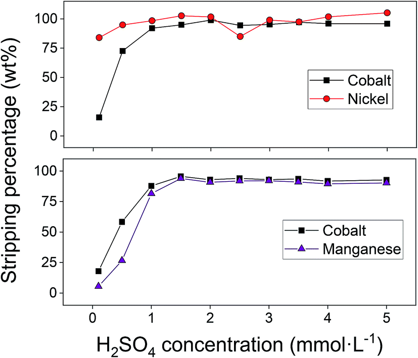 | ||
| Fig. 10 Influence of the sulphuric acid concentration on the stripping from loaded AC–ALG-C272 (binary solutions, 50 mg AC–ALG-C272 loaded with 4.3 mg g−1 cobalt(II) and 0.6 mg g−1 nickel(II) or 4.6 mg g−1 cobalt(II) and 5.0 mg g−1 manganese(II) under optimal adsorption parameters, 10 mL stripping solution, 4 h stripping, 0.1–5 mmol L−1 H2SO4). | ||
Next, the L/S ratio of the stripping step was optimised. The results for the cobalt(II)–nickel(II) and cobalt(II)–manganese(II) systems are shown in Fig. 11. For the cobalt(II)–nickel(II) system, an L/S ratio of 100 (using 2 mmol L−1 H2SO4) was sufficient to obtain complete stripping and nearly maximum separation. As expected, nickel(II) was preferentially desorbed due to the order of the pH isotherms of Cyanex 272.61 Contacting the loaded spheres a second time with a small volume of stripping solution did not result in significantly better results compared to contacting the loaded spheres with a larger amount of stripping solution at once. Further up-concentration is therefore not possible by multiple contacts. The cobalt(II)–manganese(II) system also behaves as expected since cobalt(II) is preferentially desorbed compared to manganese(II) when using the 0.5 mmol L−1 sulphuric acid solution. Increasing the L/S ratio results in an increase in both cobalt(II) and manganese(II) stripping efficiency, although the separation factor decreases. In the cobalt(II)–manganese(II) system, it is important to optimise the separation by stripping, since selectivity could not be achieved during adsorption. A trade-off had to be made between the cobalt(II) stripping efficiency and the cobalt(II)–manganese(II) separation factor and therefore, the optimal L/S ratio was set at 200.
 | ||
| Fig. 11 Influence of the L/S ratio on the stripping from loaded AC–ALG-C272 (50 mg AC–ALG-C272 loaded with 4.6 mg g−1 cobalt(II) and 0.8 mg g−1 nickel(II) or 3.7 mg g−1 cobalt(II) and 4.3 mg g−1 manganese(II) under optimal adsorption parameters, L/S ratio of 40–300, 4 h stripping, 2 mmol L−1 H2SO4). The numbers on top of the bars indicate the cobalt(II)–nickel(II) or cobalt(II)–manganese(II) separation factors and the numbers between brackets indicate the number of contacts. | ||
Finally, the influence of the stripping time was investigated. The results of the cobalt(II)–nickel(II) and cobalt(II)–manganese(II) systems are shown in Fig. 12. For the cobalt(II)–nickel(II) system, a stripping time of 30 min was sufficient to obtain maximum cobalt(II) stripping efficiency and almost maximum cobalt(II)–nickel(II) separation. To ensure equilibrium was reached, the optimal stripping time was set at 1 h. Also in this graph it became clear that the small amount of adsorbed nickel(II) causes unusual data points as a small absolute difference in concentration results in a large relative difference in stripping percentage. In the cobalt(II)–manganese(II) system, an unexpected trend for the manganese(II) stripping was observed at short stripping times. It seems that in the beginning, manganese(II) was stripped and then re-adsorbed to the AC–ALG-C272 spheres. This can be explained by the fact that contacting the fully loaded spheres with the stripping solution initially results in the release of both cobalt(II) and manganese(II). However, as the loading of the spheres decreased, the degree of ‘free’ Cyanex 272 increased, resulting in re-adsorption of manganese(II). A glance at the separation between cobalt(II) and manganese(II) showed that partial selectivity for cobalt(II) was achieved, but the stripping solution still contained some manganese(II) contamination.
 | ||
| Fig. 12 Influence of the stripping time on the stripping from loaded AC–ALG-C272 (50 mg AC–ALG-C272 loaded with 4.3 mg g−1 cobalt(II) and 0.8 mg g−1 nickel(II) or 4.3 mg g−1 cobalt(II) and 4.6 mg g−1 manganese(II) under optimal adsorption parameters, 5 mL stripping solution volume, 1 min to 6 h stripping, 2 mmol L−1 H2SO4). The numbers indicate the cobalt(II)–nickel(II) or cobalt(II)–manganese(II) separation factors. | ||
After studying binary solutions, the stripping from multi-element solutions was studied as well. The result of this experiment can be found in the ESI.†
3.5. Column experiment: case study
The AC–ALG-C272 particles were tested in a column setup on the real waste stream to consider the applicability of the system on a larger scale for the removal of metal ions from dilute aqueous (waste) solutions. The results are shown in Fig. 13. | ||
| Fig. 13 Results of the column experiment on a real waste stream. The numbers 1–7 refer to the different steps (see text), each having their own mobile phase. | ||
Although the elution of the column with dilute H2SO4 was carefully optimised, quantitative separation of cobalt(II) and manganese(II) could not be achieved. Also the recovery efficiency did not reach 100%, most likely due to the rather high pH of the eluting agent, which was considered necessary to obtain a good separation. However, complete removal of cobalt(II) and manganese(II) from the aqueous solutions was achieved when eluting with a 0.01 mol L−1 H2SO4 solution instead of the more diluted H2SO4 solutions. The recovery efficiencies for cobalt(II) and manganese(II) were 100.4 ± 1.1% and 99.8 ± 3.2%, respectively. This opens opportunities to use this technology for the simultaneous removal of cobalt(II) and manganese(II) from waste water of various industrial processes using a cobalt or manganese species as catalyst.78,79 These processes often generate waste streams contaminated with cobalt(II) and manganese(II), which cannot be discarded into the environment due to the toxic nature of these elements. It is possible to separate cobalt(II) and manganese(II) from the final solution by selective sulphide precipitation using NaSH.77 However, the chemistry behind this route is considered to be difficult and lies beyond the scope of this paper. To demonstrate the potential of the selective sulphide precipitation, without performing an optimisation study, an experiment was performed in which NaSH (150 mg) was added to the fraction of the column experiment containing the highest amount of cobalt(II) (4 mL) and removing the formed precipitate by filtration. The cobalt(II) and manganese(II) concentrations in the solution changed from 49.1 mg L−1 and 30.8 mg L−1 to 2.7 mg L−1 and 19.1 mg L−1, respectively. This corresponds to a cobalt(II) and manganese(II) precipitation efficiency of 89.6% and 37.7%, respectively. This result is not optimal as the pH of the solution needs to be low enough to restrict the amount of manganese(II) sulphide co-precipitation, but it clearly shows the potential of the selective sulphide precipitation.80–82 Although not studied in this paper, optimisation could lead to obtaining pure cobalt(II) and manganese(II) fractions.83 A flowsheet concerning the developed experimental setup was constructed and is shown in Fig. 14.
 | ||
| Fig. 14 Flowsheet of the developed experimental setup. | ||
3.6. Reusability assessment
After performing the reusability tests in a batch setup, it became evident that the material was not suited to be reused for multiple cycles. The particles increasingly lost their structure when the number of manipulations increased. The reason to this might be that the calcium(II) ions in the alginate, which are the binding force of the material, are removed from the adsorbent material after being contacted with the acidic stripping solution or that the particles lose their structure due to physical impact during shaking. Three possible solutions were considered to avoid issues with the loss of the structure of the material, namely (1) regenerating the material after stripping by contacting it with a CaCl2 solution to re-establish the calcium alginate network, (2) stripping with a saturated, acidic CaSO4 solution or (3) using the particles in a column setup without regeneration of the material. Regarding option 1, it has already been described in the literature that the regeneration of the material by contact with an CaCl2 solution was possible, but it was unclear whether this method would also work on the Cyanex 272-impregnated material.52 Unfortunately, regeneration of the adsorbent by contacting it with a 0.1 M CaCl2 solution after the stripping step did not improve the results. The particles still disintegrated and the adsorption efficiency decreased over time. Therefore, option 2 was tested. To counter the problem that calcium(II) ions are removed from the alginate binder by dissolution, a saturated (and acidic) CaSO4 solution was used during stripping. CaSO4 only has a limited solubility in water and by using a fully saturated CaSO4 solution, losses of calcium(II) from the alginate binder to the aqueous phase could be reduced or even fully eliminated. However, even when using a saturated CaSO4 solution during stripping, the spheres did not preserve their structure. Finally, a column experiment was performed to test the reusability in a column set-up (vide supra), where the physical impact on the particles was limited compared to batch shaking experiments. The parameters of the column setup were the ones in which full cobalt(II) and manganese(II) recovery was achieved. The recovery efficiencies remained constant after performing multiple adsorption and desorption cycles. Also a SEM analysis was performed on the material before and after reaction (Fig. 15). The micrographs showed that the particles remained intact and that they had a very similar size and structure, which was again a strong indication of the reusability of the material. | ||
| Fig. 15 SEM images of the AC–ALG-C272 spheres at different magnifications before and after column experiments. Before experiment: 50× (a), 250× (b) and 1000× (c); after experiment: 50× (d), 250× (e) and 1000× (f). | ||
4. Conclusions
A novel adsorbent material consisting of shaped activated carbon–alginate spheres impregnated with Cyanex 272 was synthesised and tested on the selective recovery of cobalt(II) from aqueous solutions. The adsorbent material was successful in selectively adsorbing cobalt(II) from a binary cobalt(II)–nickel(II) solution. However, cobalt(II) could not be selectively removed from binary cobalt(II)–manganese(II) solutions, since manganese(II) was co-adsorbed and could not be selectively stripped. Complete removal of cobalt(II) and manganese(II) could be achieved, which is beneficial in terms of water purification. The optimal adsorption parameters, based on 10 mL of a 0.5 mmol L−1 metal sulphate solution, were: 0.25 mol L−1 acetate buffer, pH 6.25, 1 h adsorption time, 50 mg adsorbent. The optimal stripping parameters depended on the metals present on the loaded adsorbent. The reusability tests in batch setup failed as the adsorbent beads lost their structure due to mechanical impact. However, by using the adsorbent beads in a column setup, the structure of the particles remained stable, as also indicated by SEM analysis. The column process was applied on a real waste stream from terephthalic acid production and complete cobalt(II) and manganese(II) removal was achieved.Conflicts of interest
There are no conflicts of interest to declare.Acknowledgements
This Flanders SBO (Strategic Basic Research) Project was supported by the SIM MaRes programme: Groundbreaking extraction technology for critical metals and metalloids from industrial wastewaters (Get-A-Met) [project reference number 150626]. The authors would like to thank Raymond Kemps and Clio Deferm for the SEM analyses, Dirk Henot for the CHN analyses and Gerrit Van Haele for the BET analyses.References
- F. Morar, B. Bucur and A. Stoica, Proc. Technol., 2016, 22, 425–430 CrossRef.
- C. Y. Cheang and N. Mohamed, Sep. Purif. Technol., 2016, 162, 154–161 CrossRef CAS.
- X. Zeng and J. Li, Resour., Conserv. Recycl., 2015, 104, 12–18 CrossRef.
- B. Onghena, S. Valgaeren, T. Vander Hoogerstraete and K. Binnemans, RSC Adv., 2017, 7, 35992–35999 RSC.
- S. M. Bradberry, Medicine, 2016, 44, 182–184 CrossRef.
- M. Smirniou and T. Rehren, J. Archaeol. Sci., 2013, 40, 4731–4743 CrossRef CAS.
- R. Giannini, I. C. Freestone and A. J. Shortland, J. Archaeol. Sci., 2017, 80, 27–36 CrossRef CAS.
- S. Song, D. Wang, L. Di, C. Wang, W. Dai, G. Wu, N. Guan and L. Li, Chin. J. Catal., 2018, 39, 250–257 CrossRef CAS.
- W. Chu, P. A. Chernavskii, L. Gengembre, G. A. Pankina, P. Fongarland and A. Y. Khodakov, J. Catal., 2007, 252, 215–230 CrossRef CAS.
- J. Thiessen, A. Rose, J. Meyer, A. Jess and D. Curulla-Ferré, Microporous Mesoporous Mater., 2012, 164, 199–206 CrossRef CAS.
- F. Wang, R. Sun, J. Xu, Z. Chen and M. Kang, RSC Adv., 2016, 6, 85303–85311 RSC.
- A. Valadares, C. F. Valadares, L. R. de Lemos, A. B. Mageste and G. D. Rodrigues, Hydrometallurgy, 2018, 181, 180–188 CrossRef CAS.
- P. Sommer, V. S. Rotter and M. Ueberschaar, Waste Manage., 2015, 45, 298–305 CrossRef CAS PubMed.
- R. Golmohammadzadeh, F. Faraji and F. Rashchi, Resour., Conserv. Recycl., 2018, 136, 418–435 CrossRef.
- K. Omelchuk, P. Szczepański, A. Shrotre, M. Haddad and A. Chagnes, RSC Adv., 2017, 7, 5660–5668 RSC.
- B. Huang, Z. Pan, X. Su and L. An, J. Power Sources, 2018, 399, 274–286 CrossRef CAS.
- L. Leyssens, B. Vinck, C. Van Der Straeten, F. Wuyts and L. Maes, Toxicology, 2017, 387, 43–56 CrossRef CAS PubMed.
- M. A. Islam, D. W. Morton, B. B. Johnson, B. K. Pramanik, B. Mainali and M. J. Angove, Environmental Nanotechnology, Monitoring and Management, 2018, 10, 435–456 CrossRef.
- D. A. Bertuol, C. M. Machado, M. L. Silva, C. O. Calgaro, G. L. Dotto and E. H. Tanabe, Waste Manage., 2016, 51, 245–251 CrossRef CAS PubMed.
- F. Jiang, Y. Chen, S. Ju, Q. Zhu, L. Zhang, J. Peng, X. Wang and J. D. Miller, Ultrason. Sonochem., 2018, 48, 88–95 CrossRef CAS PubMed.
- E. G. Pinna, M. C. Ruiz, M. W. Ojeda and M. H. Rodriguez, Hydrometallurgy, 2017, 167, 66–71 CrossRef CAS.
- M.-M. Wang, C.-C. Zhang and F.-S. Zhang, Waste Manage., 2016, 51, 239–244 CrossRef CAS PubMed.
- P. Zhang, T. Yokoyama, O. Itabashi, Y. Wakui, T. M. Suzuki and K. Inoue, J. Power Sources, 1999, 77, 116–122 CrossRef CAS.
- L. E. O. C. Rodrigues and M. B. Mansur, J. Power Sources, 2010, 195, 3735–3741 CrossRef CAS.
- P. Zhang, T. Yokoyama, O. Itabashi, Y. Wakui, T. M. Suzuki and K. Inoue, Hydrometallurgy, 1998, 50, 61–75 CrossRef CAS.
- B. Onghena, T. Opsomer and K. Binnemans, Chem. Commun., 2015, 51, 15932–15935 RSC.
- N. Pradhan, P. Singh, B. C. Tripathy and S. C. Das, Miner. Eng., 2001, 14, 775–783 CrossRef CAS.
- M. I. Jeffrey, W. L. Choo and P. L. Breuer, Miner. Eng., 2000, 13, 1231–1241 CrossRef CAS.
- S. Song, W. Sun, L. Wang, R. Liu, H. Han, Y. Hu and Y. Yang, J. Environ. Chem. Eng., 2019, 7, 102777 CrossRef.
- B. Krause and R. F. Sandenbergh, Hydrometallurgy, 2015, 155, 132–140 CrossRef CAS.
- Z. Zhu, P. Yoko and C. Y. Cheng, Hydrometallurgy, 2017, 169, 213–218 CrossRef CAS.
- J. Lu, D. Dreisinger and T. Glück, Hydrometallurgy, 2018, 178, 19–29 CrossRef CAS.
- G. Prabaharan and B. M. Trivedi, Hydrometallurgy, 2012, 127–128, 39–42 CAS.
- C. Kargl-Simard, J. H. Huang and A. M. Alfantazi, Miner. Eng., 2003, 16, 529–535 CrossRef CAS.
- I. G. Sharma, P. Alex, A. C. Bidaye and A. K. Suri, Hydrometallurgy, 2005, 80, 132–138 CrossRef CAS.
- F. Pagnanelli, E. Moscardini, P. Altimari, T. Abo Atia and L. Toro, Waste Manage., 2016, 51, 214–221 CrossRef CAS PubMed.
- S. I. El-Dessouky, E. A. El-Sofany and J. A. Daoud, J. Hazard. Mater., 2007, 143, 17–23 CrossRef CAS PubMed.
- K. Isshiki and E. Nakayama, Anal. Chem., 1987, 59, 291–295 CrossRef CAS.
- S. Ferreira and C. F. d. Brito, Anal. Sci., 1999, 15, 189–191 CrossRef CAS.
- M. W. Abdel-Raouf, J. A. Daoud, M. G. A. Ghoneim and A. T. Kandil, Arab J. Nucl. Sci. Appl., 2005, 38, 63–71 Search PubMed.
- K.-W. Jung, T.-U. Jeong, H.-J. Kang and K.-H. Ahn, Bioresour. Technol., 2016, 211, 108–116 CrossRef CAS PubMed.
- K.-W. Jung, B. H. Choi, M.-J. Hwang, T.-U. Jeong and K.-H. Ahn, Bioresour. Technol., 2016, 219, 185–195 CrossRef CAS PubMed.
- A. Nasrullah, A. H. Bhat, A. Naeem, M. H. Isa and M. Danish, Int. J. Biol. Macromol., 2018, 107, 1792–1799 CrossRef CAS.
- A. S. Marriott, E. Bergström, A. J. Hunt, J. Thomas-Oates and J. H. Clark, RSC Adv., 2014, 4, 222–228 RSC.
- J. Roosen, J. Pype, K. Binnemans and S. Mullens, Ind. Eng. Chem. Res., 2015, 54, 12836–12846 CrossRef CAS.
- G. Annadurai, R.-S. Juang and D.-J. Lee, Adv. Environ. Res., 2002, 6, 191–198 CrossRef.
- Y. Jodra and F. Mijangos, Sep. Sci. Technol., 2003, 38, 1851–1867 CrossRef CAS.
- Y.-B. Lin, B. Fugetsu, N. Terui and S. Tanaka, J. Hazard. Mater., 2005, 120, 237–241 CrossRef CAS.
- H. G. Park, T. W. Kim, M. Y. Chae and I.-K. Yoo, Process Biochem., 2007, 42, 1371–1377 CrossRef CAS.
- T. Y. Kim, H. J. Jin, S. S. Park, S. J. Kim and S. Y. Cho, J. Ind. Eng. Chem., 2008, 14, 714–719 CrossRef CAS.
- L. Ai, M. Li and L. Li, J. Chem. Eng. Data, 2011, 56, 3475–3483 CrossRef CAS.
- M. Lu, Y.-g. Liu, X.-j. Hu, Y. Ben, X.-x. Zeng, T.-t. Li and H. Wang, J. Cent. South Univ., 2013, 20, 2478–2488 CrossRef CAS.
- A. F. Hassan, A. M. Abdel-Mohsen and H. Elhadidy, Int. J. Biol. Macromol., 2014, 68, 125–130 CrossRef CAS PubMed.
- A. F. Hassan, A. M. Abdel-Mohsen and M. M. G. Fouda, Carbohydr. Polym., 2014, 102, 192–198 CrossRef CAS PubMed.
- A. Benhouria, M. A. Islam, H. Zaghouane-Boudiaf, M. Boutahala and B. H. Hameed, Chem. Eng. J., 2015, 270, 621–630 CrossRef CAS.
- S. Cataldo, A. Gianguzza, D. Milea, N. Muratore and A. Pettignano, Int. J. Biol. Macromol., 2016, 92, 769–778 CrossRef CAS PubMed.
- C. Li, J. Lu, S. Li, Y. Tong and B. Ye, Materials, 2017, 10, 84 CrossRef PubMed.
- Z. Tang, S. Peng, S. Hu and S. Hong, J. Colloid Interface Sci., 2017, 495, 191–199 CrossRef CAS PubMed.
- M. Funada, T. Nakano and H. Moriwaki, J. Hazard. Mater., 2018, 351, 232–239 CrossRef CAS PubMed.
- X. He, Y. Liu, H. Li and H. Li, RSC Adv., 2016, 6, 114779–114782 RSC.
- K. C. Sole, Doctor of Philosophy Doctoral dissertation, University of Arizona, 1993 Search PubMed.
- K. Wieszczycka and W. Tomczyk, J. Hazard. Mater., 2011, 192, 530–537 CrossRef CAS PubMed.
- O. S. Ayanda, F. A. Adekola, A. A. Baba, B. J. Ximba and O. S. Fatoki, Int. J. Phys. Sci., 2013, 8, 89–97 CrossRef CAS.
- Lanxess, Product Information Lewatit® TP 272, October 13th, 2011.
- J. Pype, B. Michielsen, E. M. Seftel, S. Mullens and V. Meynen, J. Eur. Ceram. Soc., 2017, 37, 189–198 CrossRef CAS.
- Z. Wang and P. Li, Mater. Sci. Eng., A, 2018, 725, 350–358 CrossRef CAS.
- J. Teichmann and K. G. van den Boogaart, Spat. Stat., 2015, 12, 65–80 CrossRef.
- H. Ribeiro de Barros, M. B. Cardoso, C. Camargo de Oliveira, C. R. Cavichiolo Franco, D. de Lima Belan, M. Vidotti and I. C. Riegel-Vidotti, RSC Adv., 2016, 6, 9411–9420 RSC.
- Y. Liu, K. Li, B. Ge, L. Pu and Z. Liu, Electrochim. Acta, 2016, 214, 110–118 CrossRef CAS.
- H. Tamai, K. Shiraki, T. Shiono and H. Yasuda, J. Colloid Interface Sci., 2006, 295, 299–302 CrossRef CAS.
- A. Z. Alothman, Materials, 2012, 5, 2874–2902 CrossRef.
- P. K. Parhi, S. Panigrahi, K. Sarangi and K. C. Nathsarma, Sep. Purif. Technol., 2008, 59, 310–317 CrossRef CAS.
- Cyanex® 272, https://www.solvay.com/en/product/cyanex-272, accessed 3 May, 2019.
- R. K. Mishra, P. C. Rout, K. Sarangi and K. C. Nathsarma, Trans. Nonferrous Met. Soc. China, 2016, 26, 301–309 CrossRef CAS.
- C. Ringwald and V. Ball, RSC Adv., 2016, 6, 4730–4738 RSC.
- L. M. Agneessens, L. D. M. Ottosen, M. Andersen, C. Berg Olesen, A. Feilberg and M. V. W. Kofoed, Bioresour. Technol., 2018, 258, 33–40 CrossRef CAS.
- C. J. Ferron, The control of manganese in acidic leach liquors, with special emphasis to laterite leach liquors, Report #2002-02, SGS Mineral Services, 2002 Search PubMed.
- A. Mukherjee and D. Milstein, ACS Catal., 2018, 8, 11435–11469 CrossRef CAS.
- V. A. Adamian and W. H. Gong, in Liquid Phase Aerobic Oxidation Catalysis: Industrial Applications and Academic Perspectives, ed. S. S. Stahl and P. L. Alsters, 1st edn, 2016, pp. 429–454, DOI:10.1002/9783527690121.
- J. Jandová, K. Lisá, H. Vu and F. Vranka, Hydrometallurgy, 2005, 77, 75–79 CrossRef.
- J. G. Fairchild, Ind. Eng. Chem., Anal. Ed., 1939, 11, 326–327 CrossRef CAS.
- A. W. Bryson and C. H. Bijsterveld, Hydrometallurgy, 1991, 27, 75–84 CrossRef CAS.
- W. Zhang and C. Y. Cheng, Hydrometallurgy, 2007, 89, 160–177 CrossRef CAS.
Footnote |
| † Electronic supplementary information (ESI) available. See DOI: 10.1039/c9ra02344e |
| This journal is © The Royal Society of Chemistry 2019 |