 Open Access Article
Batch microfabrication and testing of a novel silicon-base miniaturized reference electrode with an ion-exchanging nanochannel array for nitrite determination
Jiawen Yin a,
Wei Zhang*b,
Zan Zhanga,
Han Jina,
Wanlei Gaoa,
Jiawen Jiana and
Qinghui Jin*ab
aFaculty of Electrical Engineering and Computer Science, Ningbo University, Ningbo, 315211, P. R. China. E-mail: jinqinghui@nbu.edu.cn
bState Key Laboratory of Transducer Technology, Center for Excellence in Superconducting Electronics, Shanghai Institute of Microsystem and Information Technology, Chinese Academy of Sciences, Shanghai 200050, P. R. China. E-mail: wei.zhang@mail.sim.ac.cn; jinqh@mail.sim.ac.cn
First published on 25th June 2019
Abstract
The reference electrode (RE) provides a stable potential for electrochemical detection; therefore, the RE plays an important role in environmental monitoring. In this paper, a novel batch of microfabricated silicon-base miniaturized Ag/AgCl RE was reported. A specially designed mini-tank for saturated KCl solution storage and a nanochannel array for ion-exchange were fabricated on a 4 inch (100) silicon wafer using a two-step KOH anisotropic etching process. An Ag/AgCl electrode was fabricated on a 4 inch Pyrex 7740 glass substrate. Finally, the finished silicon and glass substrates were anode bonded to form the entire system. By comparing with a conventional solid-state Ag/AgCl RE in electrochemical microsensors, a pre-packaged saturated KCl solution in the mini-tank provided a stable working environment for the Ag/AgCl electrode to ensure a constant reference potential. Compared with a routine glass-structured RE and by replacing the ion-exchange membrane with a nanochannel array, the miniaturized RE achieved a longer lifetime. The size of the finished miniaturized RE electrode was 11 mm × 14 mm. The reference potential variation was only 0.1 mV under continuous testing for 3000 s. The standard deviation in the reference potential was only 1.314 mV in different Na2SO4 buffer concentrations ranging from 3 mM to 30 mM. To verify the practicality of the novel silicon-base miniaturized RE, the fabricated RE was applied to measure the amount of nitrite in a water sample and achieved a better linearity of R2 = 0.998. This miniaturized RE showed better reference potential stability and consistency because of the batch fabrication technique. This novel strategy for the design and manufacture of the miniaturized RE shows a bright future in the wide use of electrochemical sensors in online monitoring of water pollutants.
1. Introduction
Waste production from agriculture, industrial sewage, and animal and human activities is affecting the boundaries between clean water and wastewater, causing a reduction in the fresh water supply for humans. Biological and chemical contaminants in tap and drinking water initiate the spread of contagious diseases. Therefore, fast and sensitive detection techniques are crucial to ensure a safe and clean water supply. Several water monitoring techniques are available, including conventional instrumental analysis (laboratory-based analysis),1,2 sensor placement approach,3 microfluidic devices,4,5 spectroscopic approaches,6,7 and biosensors.8,9 For the online monitoring demand, electrochemical detection technology is widely used because of its high sensitivity, low cost, high-speed detection, miniaturization, easy integration, and convenient application.10–12 An electrochemical detection system consists of a working electrode (WE), reference electrode (RE), and counter electrode (CE). The RE provides a stable reference potential for the electrochemical detection system to ensure that the potentials of the WE are accurate. Therefore, a RE with excellent performance is the key for the accurate detection of all analytes.Many types of REs are available, such as a calomel electrode, hydrogen electrode, and silver chloride electrode.13–16 In the field of water ion detection, the Ag/AgCl electrode is the most common RE. The glass cavity of the electrode has a certain concentration of KCl solution, and the internal solution is separated from the external water environment using a porous glass. During detection, chloride ions diffuse through the porous film, decreasing the concentration of chloride ions. Because the potential of the electrode satisfies the Nernst equation, a decrease in the concentration of chloride ions corresponds to a change in the reference potential. Recently, to develop a more stable, more convenient, and low cost RE, studies on Ag/AgCl RE have mainly focused on the variation in the electrolyte of the electrode, variation in the structure of the RE, and miniaturization and integration of the electrode. Suzukia et al. designed a liquid-junction Ag/AgCl RE using microfabrication techniques. They used a novel thin-film Ag/AgCl structure. The container for the internal electrolyte solution was developed by the anisotropic etching of a silicon substrate. A cellulose-acetate-plug junction instead of a salt bridge was used to ensure that the electrode could maintain a potential of ±1 mV over a few hours.17 The miniaturization of a RE is mostly achieved by changing the internal reference liquid, that is, by replacing the liquid electrolyte with a gel electrolyte or an all-solid electrolyte.18–21 Ciobanu et al. reported the manufacturing and performance of miniaturized REs with wide applicability and highly stable potential in both aqueous and organic media. The REs showed a potential stability of ±0.5 mV over 30 h and a low-temperature coefficient of 0.15 mV K−1.18 The miniaturized RE could be produced with a small size and low cost, but this does not mean that the ions present inside the gel do not flow out. The lifetime of an electrode is still a severe problem; therefore, studies on the salt bridge of REs have continued.22,23 Pedrotti et al. designed a high-density microporous polyethylene for a restricted flow junction between the internal and external electrolytes. The more favorable characteristics of a microporous membrane for the fabrication of miniaturized junctions are evident in a commercial Vycor membrane.22 Zevenbergen et al. conducted a quantitative study on the relationship between the micropore size and chloride drift. They found that the diameter of the micropores and the loss of chloride ions are linearly related. When the hole diameter was 20 μm, the potential change was 0.01 mV per day during the testing for two months.23 In addition, some special applications and integration studies on Ag/AgCl REs have been reported.24–26 Hayashi et al. invented a RE to use in a flow-type measuring apparatus by incorporating an immobilized enzyme WE.24 To eliminate the need for a separate RE and facilitate the use of an ion-sensitive field-effect transistor, an all-solid-state RE integrated with ISFET in one chip has been developed.26
The role of a RE in an electrochemical system is to provide a stable reference potential under different buffer concentrations during the detection over a long period of time. The reaction on the surface of a Ag/AgCl electrode can be expressed as the following two processes in a certain concentration of KCl solution27:
| Ag+ + e− ⇆ Ag | (1) |
| Ag+ + Cl− ⇆ AgCl | (2) |
When the reaction reaches dynamic equilibrium, the potential of the electrode stabilizes to a fixed value. Fig. 2 shows the electrode operation. The potential satisfies the following Nernst equation:28
 | (3) |
![[thin space (1/6-em)]](https://www.rsc.org/images/entities/char_2009.gif) aCl−:
aCl−:
E = 0.2224 − 0.05916![[thin space (1/6-em)]](https://www.rsc.org/images/entities/char_2009.gif) lg lg![[thin space (1/6-em)]](https://www.rsc.org/images/entities/char_2009.gif) a(Cl−) a(Cl−)
| (4) |
Therefore, it is important to maintain the stability of the chloride ion concentration in the internal reference liquid at a constant temperature.
Nutrient salts refer to the inorganic salts of nitrogen, phosphorus, and silicon in seawater. They are essential elements for the growth of marine algae, the primary produce of ocean and the basis of the marine food chain. Excess nutrients can lead to the eutrophication of seawater. This can cause red tides, green tides, and marine pollution, leading to the death of marine life and even leading to air pollution.29 Therefore, it is important and necessary to establish a large-scale, real-time, and high-precision nutrient salt detection network to prevent the occurrence of natural disasters.
To achieve the large-scale and real-time detection of the water environment, in this study, a novel silicon-based miniaturized Ag/AgCl RE was designed and batch-fabricated based on the micro and nano-fabrication technology. Compared with the conventional solid-state Ag/AgCl RE used in some electrochemical microsensors, the prepackaged saturated KCl solution in the mini-tank provides a stable working environment for the Ag/AgCl electrode to ensure a constant reference potential. The batch-fabricated miniaturized Ag/AgCl RE has good accuracy, stability, and consistency. It provides a feasible technical solution for the design of detection sensors for water pollutants, making it possible to construct a large-area sensor network for water quality monitoring.
2. Experimental
2.1 Miniaturized Ag/AgCl RE design
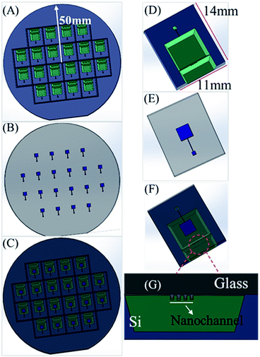
The schematics of the miniaturized Ag/AgCl RE are shown in Fig. 1. Fig. 1(A and D) show the mass production of a novel RE on a 4 inch (100) silicon wafer. A specially designed mini-tank for saturated KCl solution storage and a nanochannel array for ion-exchange were fabricated on a 4 inch (100) silicon wafer using a two-step KOH anisotropic etching process (Fig. 1D).30 The Ag/AgCl electrode was fabricated on a 4 inch Pyrex 7740 glass substrate (Fig. 1B and E). Then, the finished silicon and glass substrates were anode-bonded to form the entire system (Fig. 1C).31 The size of a separated single sensor is 14 mm × 11 mm (Fig. 1F). The schematic shows the details of the nanochannel array in Fig. 1G. Fig. 2 shows the working principle of the Ag/AgCl RE. The mini-tank is separated with the outer water sample using a beam with a width of 20 μm, 30 μm, and 40 μm. A series of channel arrays with a depth of nanometers for the chloride ion exchange were prepared on the surface of the beam by controlling the duration of KOH etching. The dimensions of the finished nanochannel array are 20–40 μm long, 15 μm wide, and less than 1 μm deep. Compared with a traditional glass tube RE, the nanochannel array of the novel RE can significantly decrease the loss of chloride ions in the KCl solution and effectively increase the service life of the RE. This shows that the drift rate of a RE reference potential is proportional to the diameter of the ion exchange channel, as obtained by Zevenbergen et al.23 The Ag/AgCl electrode with a thickness of about 0.5 μm was fabricated on a Pyrex 7740 glass using a silver sputtering lift-off process and electrochemical treatment using a HCl solution. A hole with a 1.4 mm diameter was prepared using a laser for injecting a saturated KCl solution. After dicing, the saturated KCl reference solution was filled into the mini-tank to maintain the stability of the RE reference potential. The electrode lead was welded using a conductive silver paste for electric signal collection and sealed with epoxy glue, as shown in Fig. 2. The number of nanochannels were 2, 4, 8, and 12, and their depths were 380 nm (±50 nm), 600 nm (±50 nm), 840 nm (±50 nm), and 1.8 μm (±50 nm), respectively.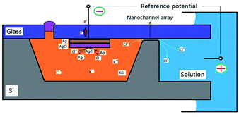 | ||
| Fig. 2 Working principle diagram of Ag/AgCl RE and a sectional view of the completed electrode chip (Fig. 1F). | ||
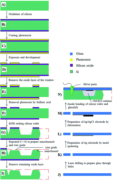
2.2 Batch fabrication process flow of miniaturized RE
The novel RE was batch-fabricated on a 4 inch (100) silicon wafer and 4 inch Pyrex 7740 glass substrate. The process flow can be divided into two parts as shown in Fig. 3: (i) processing the silicon substrate mini-tank and nanochannel array and (ii) preparation of the Ag/AgCl electrode on the glass substrate.Finally, the silicon wafer and glass substrate were cleaned using a mega-sonic instrument for 30 min, and the entire wafer was anode-bonded together.31 After dicing, a saturated KCl solution was filled into the mini-tank. The lead electrode was welded using a conductive silver paste and sealed with epoxy glue to form the miniaturized Ag/AgCl RE (Fig. 3N).
2.3 Miniaturized RE testing and nitrite determination
The microstructure was observed by scanning electron microscopy (SEM). The stability and consistency of the miniaturized RE were evaluated and tested using an electrochemical working station (Gamry Reference 600+). Comparative testing was carried out with the miniaturized RE and a conventional glass tube Ag/AgCl RE. The open-circuit voltage method was used to test the electrode potential of the RE. A Au disk electrode was used as the WE, and a Pt electrode was used as the CE. This RE was used to construct a three-electrode system for the detection of nitrite and to verify its feasibility in comparison with a glass tube RE. The amount of nitrite was determined in the concentration range from 800 μM to 10 mM using cyclic voltammetry (CV).3. Results and discussion
3.1 SEM view of nanochannel array
A typical glass tube RE uses a semipermeable membrane to exchange the internal solution with the external water environment. Previous studies have used high-density microporous polyethylene22 with a single micron hole23 instead of the semipermeable membrane of the traditional glass tube Ag/AgCl electrode. This study gradually improved the performance of the electrode, especially the life of the electrode. In this study, the specially designed and fabricated nanochannel array in the micro RE replaced the traditional semipermeable membrane as a chloride ion exchange channel for the electrode to achieve good stability and durability. Fig. 4 shows the SEM image of the beam surface channel after KOH wet etching for 9 min. The height of the channel is 840 nm and the width is 32 μm. The length is 17 μm, and the channel surface is smooth enough for the solution to flow through. The depth of the channel array can be controlled by varying the etch time (about 190 nm min−1). The surface flatness of the 4 inch silicon wafer and glass sheet after polishing is less than 60 nm, and the flatness of a single electrode chip (the length of the beam is 7 mm) is less than 5 nm. After the silicon–glass anodic bonding, the area above the beam is completely sealed except for the nanochannel array.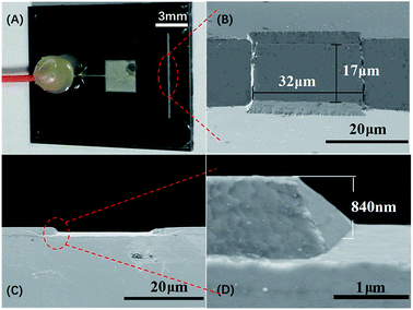 | ||
| Fig. 4 Photographs and SEM images of micro–nano device: (A) photograph of Ag/AgCl reference electrode, (B) top view, (C) cross-section view, and (D) image at zoom in mode of channel. | ||
3.2 Stability of miniaturized RE under continuous testing for a long time
Normally, the concentration of chloride ions in a KCl solution decreases during electrochemical detection due to diffusion motion. According to the Nernst equation, the reference potential will increase over time. The accuracy of detection is affected when the reference potential changes significantly. The drift rate of the RE reference potential is proportional to the diameter of the ion exchange channel, as obtained by Zevenbergen et al.23 Fig. 5 shows the stability of the electrode reference potential under the condition of continuous testing for 3000 s measured using the open-circuit voltage method in 3 mM Na2SO4 buffer. The method for measuring the reference potential of the open-circuit voltage is to test the potential between Ag/AgCl RE and an inert electrode (Pt) in the buffer. According to the Nernst equation, a decrease in the concentration of chloride ions in the reference solution increases the reference potential. Fig. 5 shows that the RE has a stable reference potential of 559.8 mV. The increment in potential within 3000 s is only 0.1 mV, which is much smaller than 1.8 mV from the glass tube electrode. We can conclude that the chloride ion loss of the miniaturized RE is slower than the glass RE from Fig. 5. A less significant drift in the potential means that the miniaturized RE has a longer life. However, the miniaturized RE showed an increment in the potential of about 185 mV compared to the glass RE. The major reason is related to the potential generated by the semiconductor and metal contact. During the RE soldering, the direct contact between the silicon and silver paste produced a contact potential of about 0.15 V.32,33 There are two other reasons. First, the small potential change is caused by the 0.2 μA leakage current in the system. Second, the contact potential is generated by the three-layer structure of the Ag electrode-silver paste-copper34 lead during the electrode welding (Fig. 3N). However, the potential generated with respect to the above-mentioned two reasons is very small. Because the internal KCl solution is in contact with the external solution through a nanochannel with a small diameter, the liquid junction potential is very small and can be excluded. This potential will be eliminated in further studies in the future. To show more details of the comparison between the micro RE potential and the glass tube RE potential, 185 mV was added to the potential of the glass tube electrode when plotting the graph.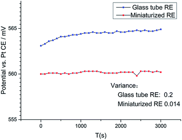 | ||
| Fig. 5 25 °C, long-term (3000 s) potential measurement of miniaturized RE in 3 mM Na2SO4 buffer solution and comparison with glass tube electrode under the same external conditions. | ||
3.3 Stability of miniaturized RE under different buffer concentrations
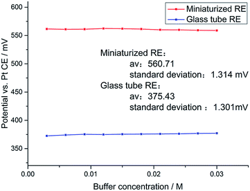
To prove that the electrodes can be used in a complex field environment, a comparison test was carried out for the potential stability of the RE under different concentrations of electrolyte. The open-circuit voltage method was used to determine the change in the potential of the RE in different concentrations of a Na2SO4 solution at pH = 7. The concentration of the Na2SO4 solution ranged from 3 mM to 30 mM, and the concentration gradient was 3 mM. Finally, the potential fluctuation of the miniaturized RE and glass tube RE at different electrolyte concentrations is shown in Fig. 6. Fortunately, Fig. 6 shows that the potential of the RE hardly drifts as the electrolyte concentration changes. Under 10 different concentrations of Na2SO4 solution, the reference potential of the miniaturized RE is 560.71 mV ± 1.314 mV. Under the same experimental conditions, the reference potential of the glass tube RE is 375.43 mV ± 1.301 mV. According to the Nernst equation,27 the potential of the RE is affected by the temperature and chloride ion concentration. Obviously, the temperature and ion concentration are constant in this experiment. This potential fluctuation is probably caused by the liquid junction potential and systematic measurement error of KCl solution and Na2SO4 solution. This change in potential does not affect the results of the electrochemical experiments.3.4 Consistency of batch-microfabricated miniaturized RE
In this study, micromachining technology was used to prepare the miniaturized RE. The ideal RE would have a smaller size, better stability, and consistency. The reference potentials of five different miniaturized REs manufactured in the same batch were measured using the open-circuit voltage method in a 3 mM Na2SO4 solution. The results are shown in Table 1. The stabilized potentials of miniaturized REs have good consistency: 0.534 V, 0.574 V, 0.559 V, 0.566 V, and 0.586 V. These REs have the same KCl concentration (3 M), temperature, and manufacturing process, but the leads are artificial and specific. Therefore, the difference in the reference potential can be attributed to the following: the lead contact uses silver paste as a conductive intermediate, and the degree of drying of the silver paste affects the magnitude of the contact potential. The impedance of the RE was used to approximately indicate the rate at which the internal chloride ions are exchanged with the external solution. The measured impedance of the miniaturized RE is 3.6–17.4 kΩ, which is higher than that of the commercial glass tube RE whose resistive impedance is 2.5 kΩ, and also higher than that of a microporous polymer junction RE22 whose resistive impedance is 0.96 kΩ.| Numbering | 1# | 2# | 3# | 4# | 5# |
|---|---|---|---|---|---|
| Potential (V) | 0.534 | 0.574 | 0.559 | 0.564 | 0.586 |
| Number of nanochannels | 2 | 4 | 8 | 12 | 12 |
| Impedance (Ω) | 17.4k | 15k | 9.1k | 3.6k | 3.4k |
3.5 Application of RE in the determination of nutrients in water
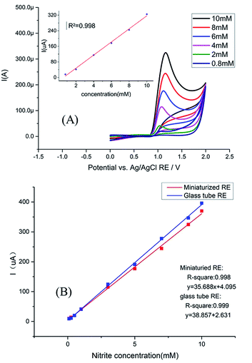
To verify the practicality of the novel silicon-base miniaturized RE in water, a non-integrated Au disk electrode was used as the WE, a non-integrated Pt electrode was used as the CE, and this miniaturized Ag/AgCl RE was used as the RE to construct a three-electrode system to detect the nitrite. In this experiment, 0.1 M PBS was selected as the buffer, and nitrite in water was detected by CV. The concentration of nitrite was in the range from 800 μM to 10 mM. The nitrite ions were oxidized to nitrate ions on the surface of the Au WE, which is accompanied by the movement of electrons. Therefore, the relationship between the current peak value on the CV curve and nitrite concentration is shown in Fig. 7A. Fig. 7A shows that the linearity between the peak current signal and nitrite concentration is good, and R2 = 0.998. This indicates that the three-electrode system can accurately determine the nitrite content. This also shows that the new RE has good stability and accuracy for nitrite detection. To further verify the performance of the new RE, a glass tube RE, the above-mentioned WE, and CE were used to form a three-electrode system using the same method and experimental conditions, but the concentration range of nitrite was slightly changed to detect the nitrite content in water. Fig. 7B shows the linear relationship between the nitrite concentration and the peak of the CV curve in two cases, and their R2 is 0.998 and 0.999. This indicates that the RE can be used for complex practical applications with better stability and durability, as shown in Section 3.2.The stability and consistency of the batch-microfabricated miniaturized Ag/AgCl RE were compared with previously reported Ag/AgCl REs17,18,23,26 and were given in Table 2.
| Innovation | Stability | Batch manufacturing (yes/no) | Ref. |
|---|---|---|---|
| A liquid-junction Ag/AgCl reference electrode with a pin-hole was used for the liquid junction | ±1 mV for several h | No | 17 |
| Stable and reproducible MREs were obtained by incorporating Ag/AgiX internal reference elements in an acrylic type hydrogel | ±0.5 mV/30 h | No | 18 |
| Single micron hole as the ion exchange channel on PCB substrate | ±0.1 mV/24 h | No | 23 |
| A novel agarose-stabilized KCl-gel membrane as a polymer-supported solid reference electrolyte and an ionic bridge | 0.45 mV h−1 | Yes | 26 |
| Typical glass tube electrode | 1.8 mV h−1 | No | — |
| Nanochannel array instead of ion exchange membrane | 0.1 mV h−1 | Yes | This work |
4. Conclusions
A novel batch-microfabricated silicon-base miniaturized Ag/AgCl (RE) was successfully developed. Tests show that the miniaturized RE has good stability, consistency, and is suitable for actual water pollution determination. This study provides a feasible technical solution for the design of electrochemical sensors for environmental water monitoring. We demonstrated that this miniaturized RE has the advantages of a small size, better reference potential stability, and performance consistency because of the batch fabrication technique. Moreover, because the fabrication of the RE is compatible with standard MEMS technology, it is expected that miniaturized multiparameter electrochemical sensors can be manufactured by integrating diverse WEs with this proposed RE. This novel strategy for the design and manufacturing of miniaturized REs has a bright future in the extensive use of electrochemical sensors for the online monitoring of water pollutants. However, two aspects should be improved: first, it should be ensured that the change in electrode potential with temperature and KCl solution concentration is in accordance with the Nernst equation. Second, the soldering of the sensor is still manual and specific, and the soldering method has a contact potential and affects the consistency of the electrode chip. These problems will be optimized in future studies.Conflicts of interest
There are no conflicts to declare.Acknowledgements
This work was financially supported by the grants received from the National Science Foundation of China (No. 61871243), Natural Science Foundation of Zhejiang Province (No. LGF18F010004 and No. LQ19F010004), and China postdoctoral Science Foundation (No. 2018M642384). This study was also sponsored by K. C. Wong Magna Fund in Ningbo University.Notes and references
- M. S. Han and D. H. Kim, Naked-eye detection of phosphate ions in water at physiological pH: a remarkably selective and easy-to-assemble colorimetric phosphate-sensing probe, Angew. Chem., 2002, 114(20), 3963–3965 CrossRef.
- W. L. Daniel, M. S. Han and J. S. Lee, et al., Colorimetric nitrite and nitrate detection with gold nanoparticle probes and kinetic end points, J. Am. Chem. Soc., 2009, 131(18), 6362–6363 CrossRef CAS PubMed.
- Z. Zou, A. Jang and E. MacKnight, et al., Environmentally friendly disposable sensors with microfabricated on-chip planar bismuth electrode for in situ heavy metal ions measurement, Sens. Actuators, B, 2008, 134(1), 18–24 CrossRef CAS.
- G. Mills and G. Fones, A review of in situ methods and sensors for monitoring the marine environment, Sens. Rev., 2012, 32(1), 17–28 CrossRef.
- C. D. M. Campos and J. A. F. da Silva, Applications of autonomous microfluidic systems in environmental monitoring, RSC Adv., 2013, 3(40), 18216–18227 RSC.
- S. Kurbanoglu, M. A. Unal and S. A. Ozkan, Recent developments on electrochemical flow injection in pharmaceuticals and biologically important compounds, Electrochim. Acta, 2018, 287, 135–148 CrossRef CAS.
- K. M. Miranda, M. G. Espey and D. A. Wink, A rapid, simple spectrophotometric method for simultaneous detection of nitrate and nitrite, Nitric Oxide, 2001, 5(1), 62–71 CrossRef CAS PubMed.
- H. S. Lo, K. W. Lo and C. F. Yeung, et al., Rapid visual and spectrophotometric nitrite detection by cyclometalated ruthenium complex, Anal. Chim. Acta, 2017, 990, 135–140 CrossRef CAS PubMed.
- I. Vopálenská, L. Váchová and Z. Palková, New biosensor for detection of copper ions in water based on immobilized genetically modified yeast cells, Biosens. Bioelectron., 2015, 72, 160–167 CrossRef PubMed.
- P. Biswas, A. K. Karn and P. Balasubramanian, et al., Biosensor for detection of dissolved chromium in potable water: a review, Biosens. Bioelectron., 2017, 94, 589–604 CrossRef CAS PubMed.
- M. Govindhan, B. R. Adhikari and A. Chen, Nanomaterials-based electrochemical detection of chemical contaminants, RSC Adv., 2014, 4(109), 63741–63760 RSC.
- D. Ning, H. Zhang and J. Zheng, Electrochemical sensor for sensitive determination of nitrite based on the PAMAM dendrimer-stabilized silver nanoparticles, J. Electroanal. Chem., 2014, 717, 29–33 CrossRef.
- G. Amala and S. M. Gowtham, Recent advancements, key challenges and solutions in non-enzymatic electrochemical glucose sensors based on graphene platforms, RSC Adv., 2017, 7(59), 36949–36976 RSC.
- A. K. Covington, J. V. Dobson and L. Wynne-Jones, The calomel electrode—I. Evaluation of the standard potential at 25° and the activity coefficients of hydrochloric acid solutions, Electrochim. Acta, 1967, 12(5), 513–523 CrossRef CAS.
- I. Dendo, Precision silver/silver chloride electrodes//International Conference of the IEEE Engineering in Medicine & Biology Society, IEEE, 1994 Search PubMed.
- M. J. De Giz, S. A. S. Machado and L. A. Avaca, et al., High area Ni-Zn and Ni-Co-Zn codeposits as hydrogen electrodes in alkaline solutions, J. Appl. Electrochem., 1992, 22(10), 973–977 CrossRef CAS.
- H. Suzuki, T. Hirakawa and S. Sasaki, et al., Micromachined liquid-junction Ag/AgCl reference electrode, Sens. Actuators, B, 1998, 46(2), 146–154 CrossRef CAS.
- M. Ciobanu, J. P. Wilburn and N. I. Buss, et al., Miniaturized reference electrodes based on Ag/AgiX internal reference elements. I. Manufacturing and performance, Electroanalysis, 2002, 14(14), 989–997 CrossRef CAS.
- Z. Zhao, H. Tu and E. G. R. Kim, et al., A flexible Ag/AgCl micro reference electrode based on a parylene tube structure, Sens. Actuators, B, 2017, 247, 92–97 CrossRef CAS PubMed.
- I. Shitanda, M. Komoda and Y. Hoshi, et al., An instantly usable paper-based screen-printed solid-state KCl/Ag/AgCl reference electrode with long-term stability, Analyst, 2015, 140(19), 6481–6484 RSC.
- A. Kisiel, H. Marcisz and A. Michalska, et al., All-solid-state reference electrodes based on conducting polymers, Analyst, 2005, 130(12), 1655–1662 RSC.
- J. Pedrotti, L. Angnes and I. G. R. Gutz, Miniaturized reference electrodes with microporous polymer junctions, Electroanalysis, 1996, 8(7), 673–675 CrossRef.
- M. A. G. Zevenbergen, G. Altena and V. A. T. Dam, et al., Solid state pH and chloride sensor with microfluidic reference electrode//Electron Devices Meeting (IEDM), 2016 IEEE International, IEEE, 2016, pp. 26.1.1–26.1.4 Search PubMed.
- R. Hayashi, K. Akio and Y. Hashizume, Reference electrode and a measuring apparatus using the same, US Pat. 5,037,527, 1991-8-6.
- T. Rim, K. Kim and N. Hong, et al., Investigation of the electrical stability of Si-nanowire biologically sensitive field-effect transistors with embedded Ag/AgCl pseudo reference electrode, RSC Adv., 2013, 3(21), 7963–7969 RSC.
- I. Y. Huang, R. S. Huang and L. H. Lo, Improvement of integrated Ag/AgCl thin-film electrodes by KCl-gel coating for ISFET applications, Sens. Actuators, B, 2003, 94(1), 53–64 CrossRef.
- D. J. G. Ives, G. J. Janz and C. V. King, Reference electrodes: theory and practice, J. Electrochem. Soc., 1961, 108(11), 246C–247C CrossRef.
- D. Pletcher, A first course in electrode processes, Royal Society of Chemistry, 2009, pp. 8–13 Search PubMed.
- X. Han, X. Wang and X. Sun, et al., Nutrient distribution and its relationship with occurrence of red tide in coastal area of East China Sea, Yingyong Shengtai Xuebao, 2003, 14(7), 1097–1101 CAS.
- J. Haneveld, H. Jansen and E. Berenschot, et al., Wet anisotropic etching for fluidic 1D nanochannels, J. Micromech. Microeng., 2003, 13(4), S62 CrossRef CAS.
- T. Rogers and J. Kowal, Selection of glass, anodic bonding conditions and material compatibility for silicon-glass capacitive sensors, Sens. Actuators, A, 1995, 46(1–3), 113–120 CrossRef CAS.
- E. H. Rhoderick, Metal-semiconductor contacts, IEE Proc., Part I: Solid-State Electron Devices, 1982, 129(1), 1 CAS.
- W. Mönch, Metal-semiconductor contacts: electronic properties, Surf. Sci., 1994, 299, 928–944 CrossRef.
- L. H. Fisher, Contact potentials between metals: history, concepts, and persistent misconceptions, Am. J. Phys., 1976, 44(5), 464 CrossRef CAS.
| This journal is © The Royal Society of Chemistry 2019 |

