
 Open Access Article
 This Open Access Article is licensed under a Creative Commons Attribution-Non Commercial 3.0 Unported Licence
Triple phase boundary and power density enhancement in PEMFCs of a Pt/C electrode with double catalyst layers†
Dung Van Dao ab,
Ganpurev Adilbisha,
Thanh Duc Lea,
In-Hwan Lee*c and
Yeon-Tae Yu*a
ab,
Ganpurev Adilbisha,
Thanh Duc Lea,
In-Hwan Lee*c and
Yeon-Tae Yu*a
aDivision of Advanced Materials Engineering, Research Center for Advanced Materials Development, Chonbuk National University, Jeonju 54896, South Korea. E-mail: yeontae@jbnu.ac.kr
bDepartment of Chemistry, Danang University of Science and Education, Danang-550000, Vietnam
cDepartment of Materials Science and Engineering, Korea University, Seoul 02841, South Korea. E-mail: ihlee@korea.ac.kr
First published on 20th May 2019
Abstract
Exploring efficient approaches to design electrodes for proton exchange membrane fuel cells (PEMFCs) is of great advantage to overcome the current limitations of the standard platinum supported carbon (Pt/C) catalyst. Herein, a Pt/C electrode consisting of double catalyst layers (DCL) with low Pt loading of around 0.130 mgPt cm−2 is prepared using spray and electrophoresis (EPD) methods. The DCL electrode demonstrated a higher electrochemical surface area (ECSA-52.5 m2 gPt−1) and smaller internal resistance (133 Ω) as compared to single catalyst layer (SCL) sprayed (37.1 m2 gPt−1 and 184 Ω) or EPD (42.4 m2 gPt−1 and 170 Ω) electrodes. In addition, the corresponding DCL membrane electrode assembly (MEA), which consists of a Pt/C DCL electrode at the anode side and a Pt/C sprayed electrode at the cathode side, also showed improved PEMFC performance as compared to others. Specifically, the DCL MEA generated the highest power density of 4.9 W mgPt−1, whereas, the SCL MEAs only produced 3.1 and 3.8 W mgPt−1, respectively. The superior utilization of the Pt catalysts into the DCL MEA can originate from the enrichment of the triple phase boundary (TPB) presented on the Pt/C DCL electrode, which can strongly promote the adsorbed hydrogen intermediates' removal from the anode side, thus improving the overall PEMFC performance.
Introduction
Because of high energy conversion efficiency and low emission advantages,1,2 proton exchange membrane fuel cells (PEMFCs), which can convert chemical energy into electrical energy, are of great potential for substituting batteries in the portable devices and vehicles of the future. In the state-of-the-art PEMFCs, platinum nanoparticle (NP: 2–5 nm) supported carbon black (Pt/C) is considered as the current standard catalyst.3 The Pt/C catalyst is of high surface areas (30 and 90) m2 gPt−1,4 which significantly contributes to both high specific activity and high mass activity.5 Furthermore, it provides sufficient porosity to speed the transport of the reactants.6,7 Unfortunately, the Pt/C catalyst shows deficiencies, which can defer the commercialization of PEMFCs, such as the aggregation and detachment of the Pt catalyst, and the corrosion of carbon supports during the electrocatalytic reactions.8,9 In addition, the activity of the Pt/C catalyst is further affected by the deposition methods on the conductive substrates.10,11 Commonly, the PEMFC electrodes were prepared by mixing the Pt/C catalyst and ionomer; then the homogeneous slurry was loaded onto the surface of the gas diffusion layer (GDL) by conventional methods, including spray and decal, etc. However, these methods cannot situate all of the Pt catalyst nanoparticles at the front of the membrane.12 It may greatly reduce the Pt catalytic utilization since the generated protons on the Pt catalyst immediately pass across the membrane without any extinction.13 On the other hand, the conventional methods could significantly decrease the amount of the triple phase boundary (TPB) because the Pt catalysts often localized in the thick conventional layer and a part of the Pt catalysts supported on carbon were not contacted to ionomer, thus it can be inactive and inaccessible to fuels.14 In the PEMFCs performance, the electrochemical reactions (hydrogen and methanol oxidation reaction at anode and oxygen reduction reaction (ORR) at cathode) mainly occurs at the TPB zones, where the catalytic particles, electrolyte phase, and gases pores intersect.15 These redox reactions necessitate fuels transport in the electrode porous area, ionic transport in the electrolyte, and charge transport in the electrodes. It means that the TPBs may strongly influence the activity and durability of the PEMFC electrodes.16 Therefore, exploring efficient methods to deposit the catalysts on the electrodes for enriching the TPBs and then maximizing catalytic utilization are of great significance.In this respect, the electrophoresis deposition (EPD) is an effective pathway to overcome the remained drawbacks of conventional methods, which can be beneficial to uniformly disperse the Pt catalysts on the conductive substrates.17 The colloidal EPD process is consisted of two main stages, in which charged particles in colloidal solution move toward an electrode with opposite charge under an applied electric field, and then deposit onto the surface of substrate. The EPD presents relatively short processing times, good uniformity, and adequate control of deposit thickness onto the surface of electrode,18,19 as well as making sure that the catalysts are well attached to the conductive substrates. Especially, the Pt catalysts can easily be located near the surface of electrodes by using the EPD method.20 After that, the obtained catalytic layer will directly be contacted to the membrane during preparing the membrane electrode assembly (MEA). It is of much importance to enhance the TPB zones and expose more catalytic active sites to fuels, whose factors greatly improve the electrocatalytic properties. Unfortunately, the EPD process can produce the relative agglomeration of the Pt catalyst when increasing the loading amount,20 because of the agglomeration between neighboring catalyst particles,21 it is a big disadvantage to reduce the TPBs and mass-specific activity of the catalyst electrodes. On the other hand, great efforts have been targeted for the development of cathode catalysts for ORR activity, while less attention has been aimed at design of anode catalysts for hydrogen oxidation reaction (HOR).22 Furthermore, the HOR involves dissociate adsorption of molecular dihydrogen on Pt catalysts (Tafel step: 1/2H2 + M → M–Had) followed by direct oxidation to protons (Volmer step: M–Had → M + H+ + e−).23 So, the kinetics were primarily influenced by M–Had surface energetics and the adsorbed H species were considered as intermediates onto the Pt catalyst. Accordingly, designing new electrocatalysis for improving the TPBs and HOR activity, finally, promoting the overall PEMFC performance is also of much significance.
In this work, we propose an efficient approach to prepare the Pt/C electrode with double catalyst layers (DCL) for enhancing the TPB zones for the hydrogen oxidation reaction (HOR) at the anode side in PEMFCs. The Pt catalyst loading is separated into two layers: one is formed by the spray of the Pt/C (40%) slurry (Pt-dispersed layer), and the other layer is formed by the EPD of the synthesized Pt catalyst (Pt-concentrated layer). By that, the Pt inactive catalysts in conventional layer (prepared by the conventional methods) and the aggregation of Pt catalyst on the surface electrodes (prepared by the EPD method) can be reduced significantly. This work is also aimed at maximizing the Pt catalytic utilization efficiency while minimizing the usage amount thereof. To the best of our knowledge, this new designed catalyst electrode was applied for PEMFC evaluation for the first time. The Pt-dispersed and Pt-concentrated single catalyst layer (SCL) electrodes (as called sprayed electrode and EPD electrode) are prepared for comparison as well.
Experimental
Preparation of working electrodes
Fig. 1a presents the process of the Pt/C DCL electrodes preparation via two steps. Firstly, carbon cloth substrate (5 cm × 7 cm, W1S1005, Ce-Tech Co) was dried at 60 °C for 1 h in the oven. Next, 0.53 mL of as-prepared Pt/C catalyst slurry (see ESI†) was uniformly sprayed onto the surface of the microporous layer (MPL) of carbon cloth to form Pt-dispersed layer, then dried at 60 °C for 1 h. After that, an area of 2.5 cm × 2.5 cm of the Pt/C electrode, which was cut from the Pt-dispersed electrode, was deposited with the as-synthesized Pt catalyst (see ESI†) using the EPD method to form the Pt-concentrated layer. To perform the EPD, a three-electrode electrochemical setup (Gamry instruments, Reference 3000 Potentiostat/Galvanostat/ZRA) was used. The Pt-dispersed electrode was immersed into an EPD bath containing 500 mL of Pt colloidal. A platinum plate and a saturated calomel electrode (SCE) were used as the counter and reference electrodes. Notably, the pH value of Pt solution was reduced to 2 prior to the experiments, which could support to easily move the Pt catalyst nanoparticles towards the working electrode. Furthermore, pulse current density, cycle time (tcycle = ton + toff), duty cycle {θ = ton/(ton + toff)}, and EPD bath temperature were constantly kept at 30 mA cm−2, 1 s, 25%, and 25 °C, respectively. After the completion of the EPD process, the as-fabricated DCL electrode was dried at 60 °C for overnight. The individual sprayed and EPD SCL electrodes were also prepared for comparison (see ESI†). More detail information of the prepared electrodes is provided in Table S1.†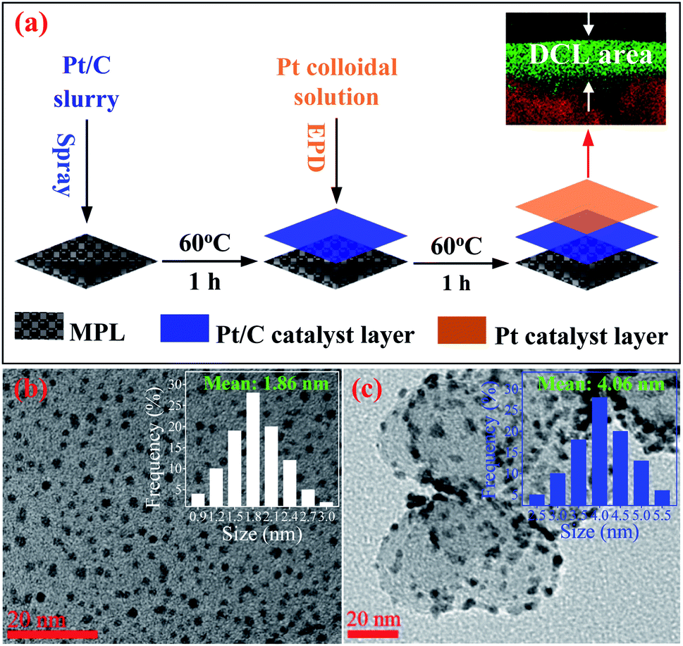 | ||
| Fig. 1 (a) The schematic for the preparation of the Pt/C double catalyst layers electrode for PEMFC. The HRTEM imageries of (b) Pt colloidal and (c) Pt/C composite catalysts, the insets showing the particle size distribution of Pt catalysts. | ||
Preparation of MEAs
First, a Nafion 212 membrane (DuPont, USA) was utilized as a proton exchange membrane (PEM) electrolyte without any pretreatment. Then, three kinds of the MEAs are prepared with the difference of the designed electrodes on anode side such as the sprayed, EPD and DCL electrodes, while the sprayed electrodes is constantly used for cathodic side activity. Thereby, the obtained devices are hereafter called as sprayed, EPD, and DCL MEAs, respectively. To handle the MEAs, two prepared electrodes were symmetrically attached to both sides of the Nafion 212 membrane, and the active geometric areas of the prepared MEAs were set to 5.0 cm2. After that, the platinum-catalysed MEAs were hot-pressed at 100 °C with the pressure of 60 kg cm−2 for 3 min. The obtained MEAs are placed between two gasket layers, then centre between two graphite plates with the fuel transfer channels. Finally, the stack fuel cell is carefully tightened using the bolts.Physical characterizations
The loading of the Pt catalyst was measured by inductively coupled plasma (ICP) spectrometry (ICPS-7500, Shimadzu), after the as-prepared catalyst electrodes were completely treated with aqua regia at 100 °C for 10 h. Then, the obtained solutions were filtered carefully to clear solid components before the ICP measurements. The size and shape of Pt/C and Pt catalyst were observed by high-resolution transmission electron microscopy (HRTEM, JEOL, JEM-2010), with an accelerating voltage of 200 kV. For HRTEM analysis, the samples were dropped onto a carbon-coated copper grid, then dried at 80 °C for overnight. The crystal structure of materials deposited on working electrodes was analysed by X-ray diffractometry (XRD, D/Max 2005, Rigaku), using CuKα radiation (λ = 1.54178 Å). The surface, cross-sectional images, and energy dispersive spectroscopy (EDS) of the working catalyst electrodes and MEAs were all observed by field emission scanning electron microscopy (FESEM, S-4800, Hitachi).Electrochemical measurements
Cyclic voltammetry (CV) curves were performed on a potentiostat (Gamry instruments, Reference 3000 Potentiostat/Galvanostat/ZRA) for the electrochemical surface area (ECSA) and electrochemical impedance spectroscopy (EIS) evaluations of the prepared catalyst electrodes. An area of 1.0 cm × 1.0 cm electrode (Fig. S1†), which is divided from the prepared electrodes, was used as working electrode. The CV tests were performed in a 500 mL glass beaker containing freshly prepared 0.5 M H2SO4 electrolyte with the sweep rate of 50 mV s−1 at room temperature. Notably, the electrolyte solutions were saturated with pure N2 by purging during the electrochemical tests, to prevent attack from the oxygen. The ECSA value of each catalyst electrode was quantitatively calculated by the following equation;| ECSA = QH/(0.21 × mPt) |
Single cell tests
The prepared fuel cell devices were tested using a fuel cell test station (SMART-II, WonAtech Com.). The humidified hydrogen and air fuels were supplied to the MEA through the serpentine flow channels on the graphite plates with the flow rate of 100 and 260 cm3 min−1, respectively. Prior to the experiments, the inside of the fuel cell devices was totally cleaned by the purge of pure nitrogen for 30 min. The back pressure and temperature were constantly controlled at 1.5 atm and 80 °C for both sides during the PEMFC operation.Results and discussion
The HRTEM imagery of the as-prepared Pt colloid is shown in Fig. 1b, it is composed of the spherical particles without any agglomeration. The inset provides the size distribution of the synthesized Pt catalysts, with the mean size of 1.86 nm. Further, Fig. 1c is the HRTEM imagery of the Pt/C catalyst, it is evident that the Pt catalyst nanoparticles are uniformly loaded on the surface of carbon black. The inset shows the size distribution of Pt catalyst loaded on carbon, with the average diameter of 4.06 nm. The size of carbon supports is also determined in the range (40 to 70) nm. Clearly, the Pt catalyst NPs have a very narrow size distribution in both cases (synthesized Pt colloidal and Pt/C composite catalyst), it is a great advantage to improve the catalytic activity of the prepared catalyst electrodes.Fig. 2a shows the XRD pattern of the Pt/C DCL electrode after the loading of the Pt-dispersed and -concentrated catalyst layers on the MPL surface. The diffraction peaks located at 25.5, 43 and 53.5° (as marked in black) could belong to the (002), (101) and (004) planes of carbon (JCPDS no. 75-1621). While the diffraction peaks located at 39.8, 46.5 and 67.5° (as marked in red) are responsible for the (111), (200) and (220) crystal planes of Pt (JCPDS no. 04-0802). The XRD analysis confirms that the Pt/C catalyst slurry and Pt catalyst nanoparticles were deposited on the surface of carbon cloth substrate by the spray and EPD processes. On the other hand, the surface morphology of the Pt/C DCL electrode is observed by the FESEM analysis. Firstly, the surface of the MPL is examined and shown in Fig. S2.† It is composed of spherical nanoparticles of carbon black with the average diameter of 50 nm. Then the Pt-dispersed catalyst layer has been sprayed onto the surface of the MPL, while there is no change of the particle size of the Pt catalyst (white dots) supported on carbon black (Fig. 2b). The Pt-concentrated catalyst layer is next deposited by the EPD process on the surface of the Pt-dispersed layer (Fig. 2c). After that, there is an increase of Pt loading on the surface of electrode, leading to the appearance of few agglomerated Pt nanoparticles. The surface images of the sprayed and EPD SCL electrodes are also provided in Fig. S3a and b.† Actually, the particle sizes of Pt catalyst after loading on the surface of electrodes have not changed as compared to the precursors. That is, the size of Pt into Pt-dispersed layer (sprayed electrode) is still 4.06 nm. In cases of EPD and DCL electrodes, the size of Pt in Pt-concentrated layer is still 1.86 nm. However, the agglomeration of Pt catalyst can strongly occur on the surface of EPD electrode, leading to a heavy backlog of Pt agglomerated particles on its surface as compared to that of DCL electrode. Fig. 2d gives the FESEM cross-sectional image of the Pt/C DCL electrode, in which the DCL area is highlighted by the red arrows. The EDS compositional line profile of the Pt/C DCL electrode is provided in Fig. 2e, and the presence of Pt catalyst and carbon support is mapped in green and red, respectively. The inset of Fig. 2e shows the thickness distribution of Pt catalysts, namely, the thickness of Pt-concentrated and Pt-dispersed layers is determined to be 0.1 μm and 4 μm. The total thickness of DCL area is 4.1 μm. Further, the Pt-dispersed catalytic thickness of sprayed electrode and Pt-concentrated catalytic layer of EPD electrode are also measured to be 8 and 2 μm, respectively (Fig. S3c and d†). The distribution of Pt loading and porosity onto the surface of Pt/C DCL electrode is simulated in Fig. 2f. Thereby, the side of the catalytic layer heading to the PEM electrolyte contains a higher Pt loading amount, it means that Pt catalyst is mainly localized in front of the PEM, which can improve remarkably the electrocatalytic reactions. While, the side heading to the gas diffusion layer (GDL) has a larger pore size to easily promote the transport of the fuels. Fig. 2g indicates the distribution of the Pt catalytic layer thicknesses in all of the prepared catalyst electrodes. In these, the Pt-dispersed thickness of the Pt/C DCL (4.0 μm) is smaller than that of the sprayed electrode (8 μm). It is greatly advantageous to reduce the Pt inactive catalysts in the conventional layer. Additionally, the Pt-concentrated thickness of the Pt/C DCL (0.1 μm) is also lower than that of the EPD electrode (1.0 μm). It contributes to remarkably reduce the number of Pt agglomerated particles on the surface of electrode as seen in FESEM surface analysis above. These results are beneficial to improve the TPB contents and catalytic active sites of MEA prepared by the DCL electrodes.
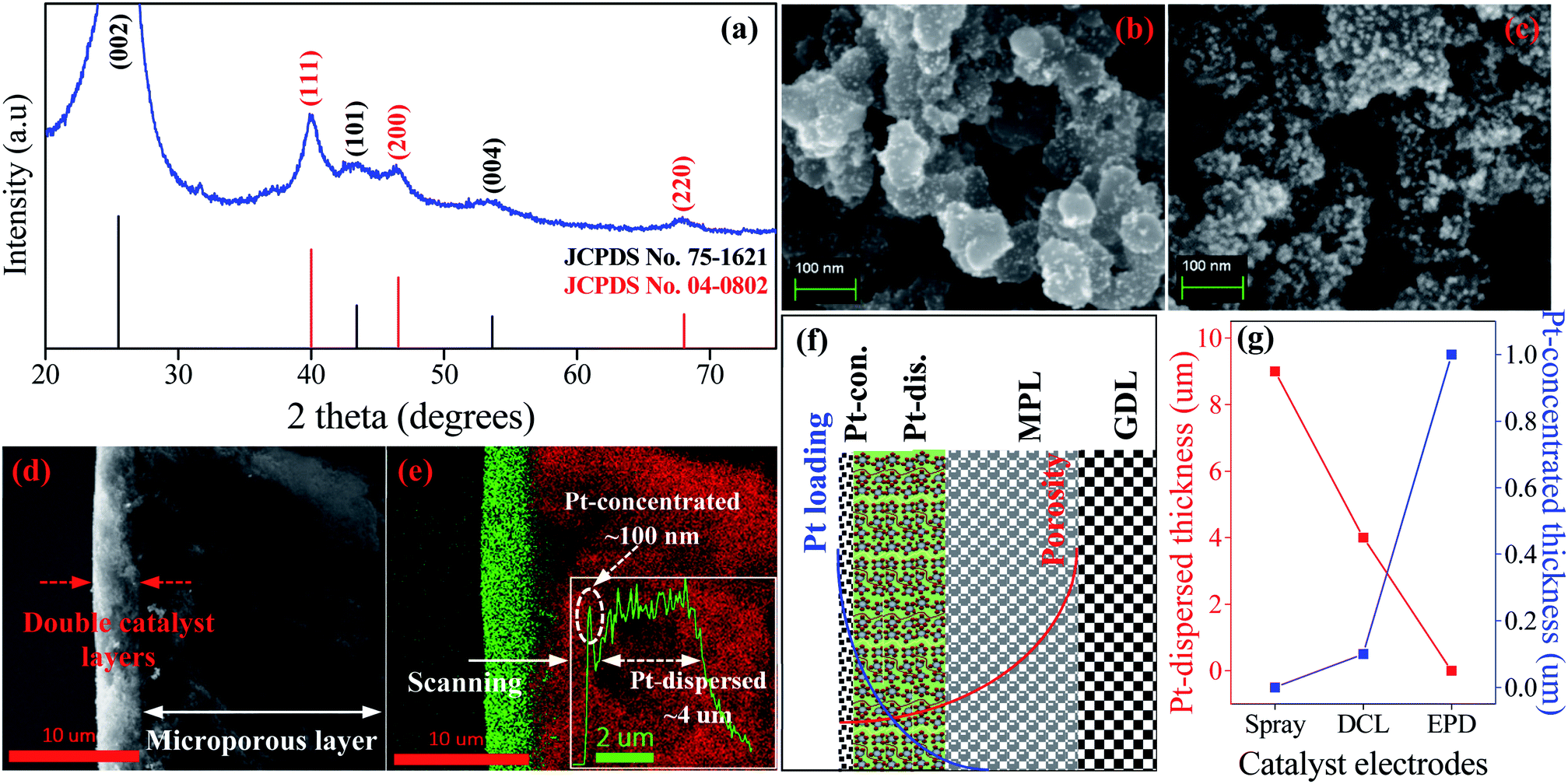 | ||
| Fig. 2 (a) The XRD pattern of the Pt/C DCL catalyst electrode. The FESEM surface image of the DCL electrode after (b) the spray of Pt/C slurry, and (c) the EPD of Pt colloidal on the MPL surface of carbon cloth. (d) An overview of FESEM cross-sectional observation of the Pt/C DCL electrode. (e) The EDS cross-sectional compositional line profile of the Pt/C DCL electrode. (f) The gradient distribution of the porosity and Pt loading into the anodic catalyst structure. (g) The distribution of the Pt catalyst thickness in the Pt/C sprayed, Pt/C EPD, and Pt/C DCL electrodes. | ||
To evaluate the ECSA of the prepared catalyst electrodes, the cyclic voltammetry was performed in N2-saturated 0.5 M H2SO4 electrolyte solution. As shown in Fig. 3a, Pt/C DCL electrode indicates larger hydrogen desorption peak areas from −0.2 to +0.1 V (vs. SCE) than those of the sprayed and EPD SCL electrodes. By using the equation given in the experimental section, the ECSA of the sprayed, EPD, and DCL working catalyst electrodes was calculated to be 37.1, 42.4, and 52.5 m2 gPt−1, respectively (Fig. 3b). The highest ECSA of Pt/C DCL electrode can be attributed to the integrated advantage of EPD and Spray manners, which is effective for oxidizing the adsorbed hydrogen  as an intermediate onto the surface of Pt catalyst, generated during the HOR performance to improve the ECSA thereof. In case of EPD electrode, the particle size of Pt catalyst is smaller than that of sprayed electrode, and the Pt catalyst is electrophoretically deposited near the surface of electrode, making it more convenient for promoting the HOR. Whereas, the bigger Pt particles loaded on carbon black, in case of sprayed electrode, were buried in ionomer, making it inaccessible to fuels. Thus, its ECSA value is inferior to EPD electrode. The ECSA durability is considered as another important parameter to the practical application of catalyst electrodes. Fig. S4† provides the CVs of the ECSA durability testing after 500 sequential cycles for the sprayed, EPD, and DCL electrodes. Obviously, the Pt/C DCL electrode demonstrates good stability with the activity drop of 24.5% only, whereas, the sprayed and EPD SCL electrodes big lose 43.6 and 37.5% activity (Fig. 3c). Furthermore, the EIS all of the as-prepared electrodes is also tested in N2-saturated 0.5 M H2SO4 electrolyte in order to verify the internal resistance. The EIS spectra include a semicircle portion and are analysed using Nyquist plots as shown in Fig. 3d. Based on an equivalent circuit as represented in Fig. S5,† where, Rs indicates the solution resistance, Rct presents the charge transfer resistance, and CPE is a constant phase element, the Rct value is calculated to be 133, 170, and 184 Ω for Pt/C DCL, EPD, and sprayed electrodes, respectively. The Pt/C DCL electrode owns the smallest internal resistance, which can promote the charge transfer as compared to others. This is believed to be due to the fact that the thickness of the Pt catalyst layer of DCL electrode is less thick than that of sprayed electrode and the agglomeration of the Pt catalyst particles is less severe than that of EPD electrode. As a result, the combination between the sprayed and EPD methods can produce efficient and stable catalyst electrode for the PEMFC application.
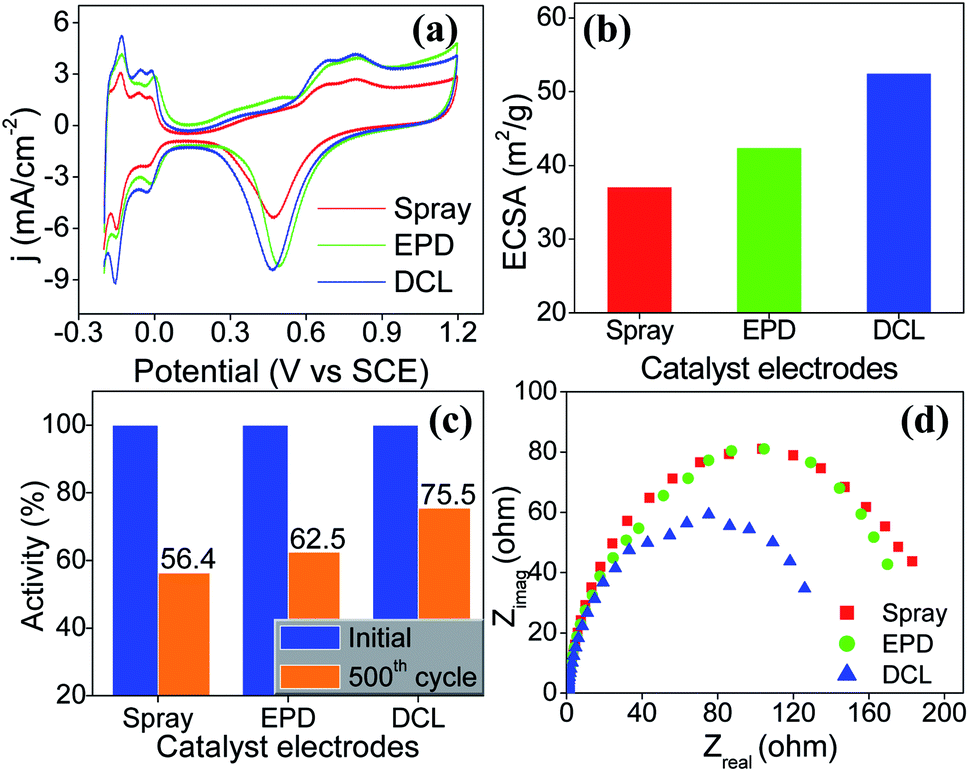 | ||
| Fig. 3 (a) Cyclic voltammetry curves of the sprayed, EPD, and DCL catalyst electrodes performed in N2-saturated 0.5 M H2SO4 electrolyte at a sweep rate of 50 mV s−1 at room temperature, (b) the corresponding ECSA value, and (c) the ECSA durability test of the prepared catalyst electrodes after 500 sequential cycles. (d) EIS Nyquist plots measured in N2-saturated solution of 0.5 M H2SO4 electrolyte at 25 °C recording from 100 kHz to 0.05 Hz for the prepared electrodes. | ||
The structure of the MEA containing the Pt/C DCL electrode at anode side and Pt/C sprayed electrode at cathode side is illustrated in Fig. S6,† in which, the multi-stacked layers of the prepared MEA is clearly simulated. The oxidation of hydrogen and the reduction of oxygen are taken place at anode and cathode in the PEMFC at the same temperature of 80 °C, respectively. The real overview structure of the prepared MEA is detected by the FESEM cross-sectional analysis as illustrated in Fig. 4a, with the PEM located at the centre of MEA. The inset shows the photograph of MEA after preparing with the active catalytic area of each side is 5 cm2. In addition, the localization of the Pt catalysts in green on both sides of MEA also observed by the EDS cross-sectional mapping (Fig. 4b). Thereby, the catalytic thickness of each electrode is not changed much after the MEA preparation. It still maintains at around 4 μm on anode side and 8 μm on cathode side, respectively. While, the thickness of the PEM electrolyte, which is the pathway of hydrogen ions conduction, is around 40 μm.
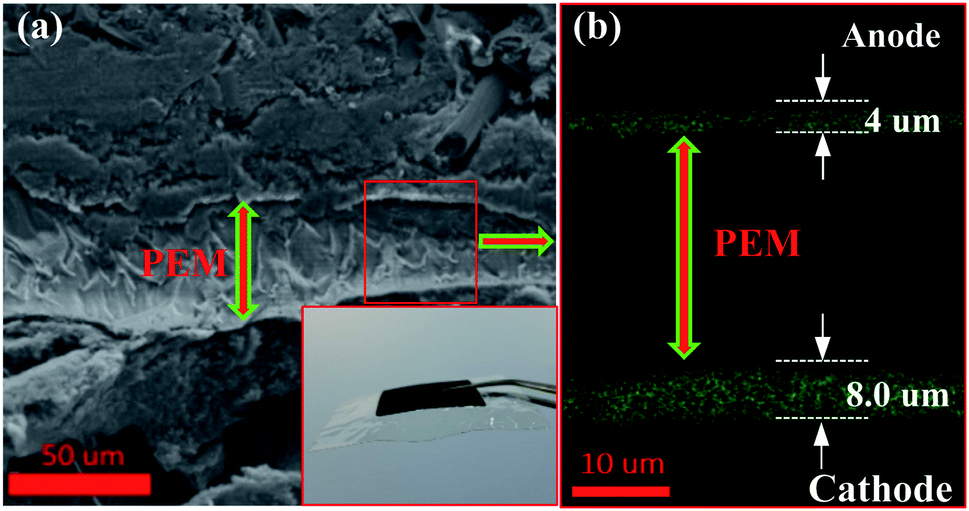 | ||
| Fig. 4 (a) The FESEM cross-sectional image of the prepared MEA containing the Pt/C DCL electrode on anode and Pt/C sprayed electrode on cathode, inset showing the photograph of prepared MEAs. (b) The thickness distribution of Pt catalysts on anode and cathode sides observed by the EDS mapping. | ||
The PEMFC performances of the sprayed, EPD, and DCL MEAs are provided in Fig. 5. Fig. 5a shows current–voltage polarization curves for three different MEAs with the same of the cathodic catalytic side. In which, the DCL MEA demonstrates higher open circuit potential of 0.911 V than those of the sprayed MEA (0.862 V) and EPD MEA (0.900 V). Clearly, at low current density, there is a little difference in the PEMFC performance for the various MEAs. At high current density, however, the DCL MEA shows superior achievement as compared to others. This phenomenon can be due to at low current density region where the activation polarization prevails, the intrinsic property of the catalyst is an important factor, whereas, the ionic conductivity of the PEM electrolyte is more essential in the ohmic polarization region at high current density.24 In addition, the output power densities of the sprayed and EPD MEAs are 0.452 W (at 0.855 A cm−2) and 0.490 W (at 0.930 A cm−2), it is largely inferior to the DCL MEA performance, being 0.636 W (at 1.108 A cm−2) as shown in Fig. 5b. By normalizing the output power and current density to the Pt loading, the mass power and current density are obtained as provided in Fig. 5c. Thereby, the DCL MEA displays the highest mass power density of 4.9 W mgPt−1, whereas, those of the sprayed and EPD MEAs are determined to be 3.2 and 3.7 W mgPt−1, respectively. Furthermore, the DCL MEA produces the mass current density of 10.7 A mgPt−1 (at 0.3 V), which is higher than those of the sprayed and EPD MEAs (7.8 and 8.9 A mgPt−1 at 0.3 V). There is no doubt that the DCL MEA shows superior PEMFC performance as compared to the sprayed and EPD MEAs.
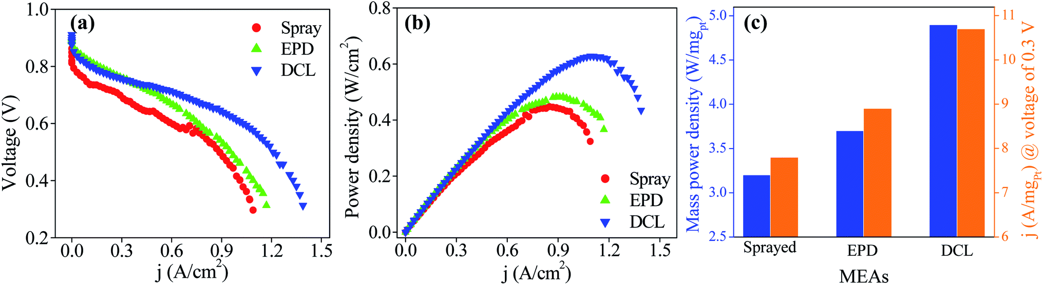 | ||
| Fig. 5 (a) PEMFC polarization and (b) power density curves of MEAs consisting of spray, EPD, and DCL electrodes for anode sides, and cathode side is constantly spray electrodes, at working temperature of 80 °C, and (c) the corresponding mass power density and mass current density. | ||
Here, we also propose the reaction mechanism at the anode sides in order to thoroughly understand the PEMFC activity of all of the prepared MEAs. The limited performance of the sprayed electrode in PEMFC is due to (1) the Pt catalysts are uniformly dispersed in a thick layer (Fig. S3c†), are not localized in front of the PEM electrolyte; (2) the some Pt catalysts are not contacted to ionomer or/and totally buried in ionomer (see Pt-dispersed layer in Fig. 6a), so these particles can be inaccessible to fuels. These drawbacks can narrow the pathways of the reactants in the prepared MEA and greatly reduce the number of the TPB zones, where is the convergence of the Pt catalysts, electrolyte, and fuels (Fig. 6b), thus, weakening the PEMFC achievement thereof. In case of the EPD electrode, the Pt catalysts are mostly located near the PEM electrolyte, thus its electrocatalytic properties are improved as compared to the sprayed MEA, but is still limited. The reason for this phenomenon is the catalytic agglomeration during the deposition (Fig. S3b†). As can be seen the Pt-concentrated layer in Fig. 6a, when increasing the EPD times, the agglomeration of the Pt catalysts can be strongly occurred on the surface of electrode. It can remarkably be decreased the TPB zones as exposed to the PEM electrolyte. The poor achievements of the sprayed and EPD electrodes toward PEMFC can be foreseen from the cyclic voltammetry and EIS analysis above. Whereas, the DCL MEA shows better PEMFC achievement as compared to others. This is due to the enrichment of the TPB zones presented on the DCL electrodes of anode side. Note that, the Pt loading onto the sprayed, EPD and DCL electrodes is almost the same. Therefore, the separation of the Pt catalysts in dispersed and concentrated layers is greatly advantageous to improve the PEMFC activity. First, the significant reduction of the Pt-dispersed catalytic thickness of the DCL electrode compared to the sprayed electrode can lower the content of Pt inactive sites in the conventional layer. Concurrently, this can supply more pathways for the H2 fuel transfer from the GDL side. On the other hand, the rest of the Pt catalyst on this electrode (ultra-thin Pt-concentrated layer ∼0.1 μm, Fig. 2e) is uniformly localized in front of the PEM electrolyte, which can greatly increase the number of the TPB zones at the interfacial contacts between the Pt-concentrated catalysts and the PEM electrolyte. As known, the oxidation of the H2 fuel in anode is mainly taken place at the TPB zone, thus, the enhancement of the TPB is of significant distribution to support more catalytic active sites to fuels and then totally oxidize H2 to 2H+. Thus, a great number of electrons could be produced from anode side, which are then reached into the cathode side to reduce oxygen. As a result, the overall PEMFC performance of the DCL MEA is improved remarkably. Of course, the enhanced catalytic activity of the DCL electrode can also be expected from the ECSA and EIS results, it shows higher ECSA value and smaller internal resistance. The DCL electrode further proves good ECSA durability as compared to the sprayed and EPD electrodes.
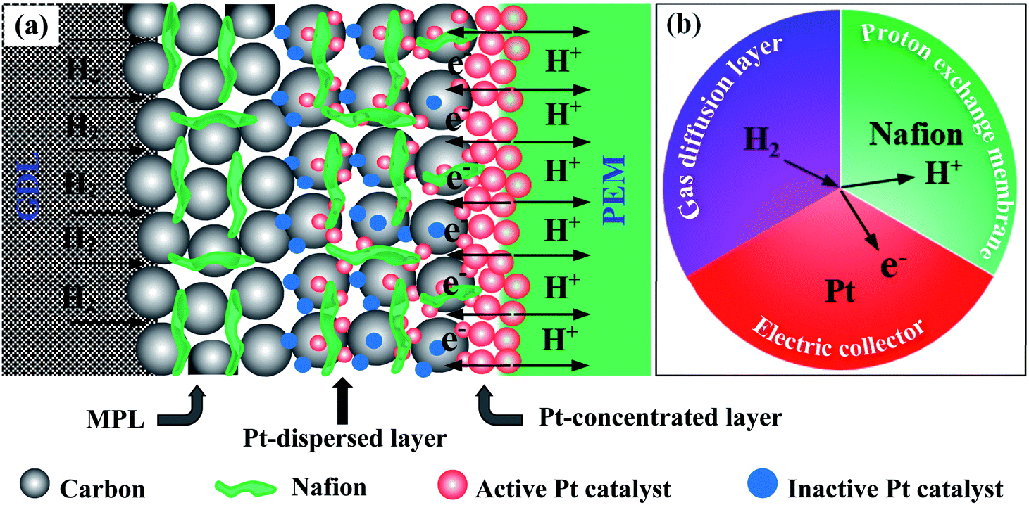 | ||
| Fig. 6 (a) The advantages of DCL electrode for enhancing the pathways of H2, electron, and proton; and TPB zones into the anodic catalyst structure in the DCL MEA. (b) Triple phase boundary simulation, where H2 (gas), Pt catalyst (solid), and Nafion (liquid) intersect. | ||
Conclusions
In this work, we demonstrated a useful pathway to fabricate the Pt/C electrode for PEMFC applications, which is composed of double catalyst layers including Pt-dispersed and -concentrated layers with low Pt content (∼0.130 mg cm−2). It presented the improved electrocatalytic properties with higher ECSA (52.5 m2 gPt−1) and smaller internal resistance (133 Ω) as compared to the SCL electrodes. Furthermore, the corresponding DCL MEA exhibited an exceptional achievement toward the PEMFC activity. The DCL MEA owned the greatest power density generation (4.9 W mgPt−1) than those of the sprayed and EPD MEAs. The improvement of the DCL MEA can be attributed to the enhancement of the TPB amount on DCL electrode, which is significant to promote the oxidation of hydrogen at anode. Therefore, it is expected that this work can open new aspect to design effective electrode using for PEMFC applications towards hydrogen oxidation reaction.Conflicts of interest
There are no conflicts to declare.Acknowledgements
This work was supported by (1) BK21 plus program from the Ministry of Education and Human-Resource Development, South of Korea; (2) National Research Foundation of Korea (NRF) grant funded by the Korean government (MSIP) (BRL No. 2015042417, 2016R1A2B4014090, 2017R1A2B3006141) and (3) LINC Plus Research Project (2018-C-G022-010102).Notes and references
- J. Wang, Z. Huang, W. Liu, C. Chang, H. Tang, Z. Li, W. Chen, C. Jia, T. Yao, S. Wei, Y. Wu and Y. Li, J. Am. Chem. Soc., 2017, 139, 17281–17284 CrossRef CAS.
- W. S. Jung and B. N. Popov, ACS Sustainable Chem. Eng., 2017, 5, 9809–9817 CrossRef CAS.
- S. Chen, Z. Wei, X. Qi, L. Dong, Y.-G. Guo, L. Wan, Z. Shao and L. Li, J. Am. Chem. Soc., 2012, 134, 13252–13255 CrossRef CAS PubMed.
- J. Ustarroz, B. Geboes, H. Vanrompay, K. Sentosun, S. Bals, T. Breugelmans and A. Hubin, ACS Appl. Mater. Interfaces, 2017, 9, 16168–16177 CrossRef CAS.
- J. Kibsgaard, Y. Gorlin, Z. Chen and T. F. Jaramillo, J. Am. Chem. Soc., 2012, 134, 7758–7765 CrossRef CAS PubMed.
- G. Gupta, D. A. Slanac, P. Kumar, J. D. Wiggins-Camacho, J. Kim, R. Ryoo, K. J. Stevenson and K. P. Johnston, J. Phys. Chem. C, 2010, 114, 10796–10805 CrossRef CAS.
- G. V. Reddy, P. Raghavendra, B. Ankamwar, P. Sri Chandana, S. M. Senthil Kumar and L. S. Sarma, Mater. Chem. Front., 2017, 1, 757–766 RSC.
- N. Macauley, D. D. Papadias, J. Fairweather, D. Spernjak, D. Langlois, R. Ahluwalia, K. L. More, R. Mukundan and R. L. Borup, J. Electrochem. Soc., 2018, 165, F3148–F3160 CrossRef CAS.
- J. Kim, J. Lee and Y. Tak, J. Power Sources, 2009, 192, 674–678 CrossRef CAS.
- R. Balgis, W. Widiyastuti, T. Ogi and K. Okuyama, ACS Appl. Mater. Interfaces, 2017, 9, 23792–23799 CrossRef CAS PubMed.
- H. E. M. Hussein, H. Amari and J. V. Macpherson, ACS Catal., 2017, 7, 7388–7398 CrossRef CAS.
- H.-S. Park, Y.-H. Cho, Y.-H. Cho, I.-S. Park, N. Jung, M. Ahn and Y.-E. Sung, J. Electrochem. Soc., 2008, 155, B455–B460 CrossRef CAS.
- G. Adilbish, J.-W. Lee, Y.-S. Jang, H.-G. Lee and Y.-T. Yu, Int. J. Hydrogen Energy, 2014, 39, 3381–3386 CrossRef CAS.
- J. Lee, J. Seo, K. Han and H. Kim, J. Power Sources, 2006, 163, 349–356 CrossRef CAS.
- A. Dhanda, H. Pitsch and R. O'Hayre, J. Electrochem. Soc., 2011, 158, B877–B884 CrossRef CAS.
- T. Hirai, T. Kinumoto, K. Katakura, Y. Iriyama, Y. Uchimoto and Z. Ogumi, ECS Trans., 2007, 11, 809–818 CAS.
- J. Kim, J. E. Dick and A. J. Bard, Acc. Chem. Res., 2016, 49, 2587–2595 CrossRef CAS PubMed.
- A. A. Daryakenari, D. Hosseini, T. Saito, A. Apostoluk, C. R. Müller and J.-J. Delaunay, RSC Adv., 2015, 5, 52578–52587 RSC.
- A. Chavez-Valdez, M. S. P. Shaffer and A. R. Boccaccini, J. Phys. Chem. B, 2013, 117, 1502–1515 CrossRef CAS PubMed.
- G. Adilbish and Y.-T. Yu, Int. J. Hydrogen Energy, 2017, 42, 1181–1188 CrossRef CAS.
- B. Geboes, J. Ustarroz, K. Sentosun, H. Vanrompay, A. Hubin, S. Bals and T. Breugelmans, ACS Catal., 2016, 6, 5856–5864 CrossRef CAS.
- E. S. Davydova, S. Mukerjee, F. Jaouen and D. R. Dekel, ACS Catal., 2018, 8, 6665–6690 CrossRef CAS.
- N. Ramaswamy, S. Ghoshal, M. K. Bates, Q. Jia, J. Li and S. Mukerjee, Nano Energy, 2017, 41, 765–771 CrossRef CAS.
- S.-H. Kawk, T.-H. Yang, C.-S. Kim and K.-H. Yoon, J. Korean Ceram. Soc., 2003, 40, 118–122 CrossRef.
Footnote |
| † Electronic supplementary information (ESI) available: Additional experimental section; photographs of the Pt/C slurry, synthesized Pt colloid, and the obtained DCL electrode; FESEM surface image of carbon cloth with the microporous layer; FESEM surface and cross-sectional images of the sprayed and EPD catalyst electrodes; CVs results of ECSA durability testing; an electrical equivalent circuit used to fit the Nyquist plots; the structural simulation of MEA containing the Pt/C DCL electrode at anode and Pt/C sprayed electrode at cathode. See DOI: 10.1039/c9ra01741k |
| This journal is © The Royal Society of Chemistry 2019 |