 Open Access Article
FeNC/MXene hybrid nanosheet as an efficient electrocatalyst for oxygen reduction reaction†
Yangyang Wen *a,
Chang Maa,
Zhiting Weia,
Xixi Zhub and
Zhenxing Li
 *a
*a
aState Key Laboratory of Heavy Oil Processing, College of New Energy and Material, China University of Petroleum (Beijing), Beijing 102249, China. E-mail: wenyangyang@cup.edu.cn; lizx@cup.edu.cn
bCollege of Chemical and Environmental Engineering, Shandong University of Science and Technology, Qingdao 266590, China
First published on 1st May 2019
Abstract
The iron–nitrogen–carbon (FeNC) catalyst, as a highly active and stable non-precious metal catalyst, has emerged as one of the most promising alternatives to replace the platinum catalyst for oxygen reduction reaction (ORR). Herein, a novel FeNC/MXene hybrid nanosheet was, for the first time, explored via pyrolysis of an iron–ligand complex and MXene nanosheets. The structure and morphology characterizations reveal that a thin and rugged FeNC coating was closely attached on the surface of MXene, forming a hybrid nanosheet structure with an excellent conductive substrate and many electrocatalytic active sites on the substrate. The electrochemical measurements disclose that the FeNC/MXene hybrid nanosheet exhibited a remarkable electrocatalytic performance, with a 25 mV higher half-wave potential (0.814 V versus RHE) than the Pt/C counterpart. More importantly, this hybrid presented a superb durability, with only 2.6% decay after a 20![[thin space (1/6-em)]](https://www.rsc.org/images/entities/char_2009.gif) 000 s continuous test, much better than the 15.8% degradation for Pt/C. This work not only demonstrates the promising performance of the FeNC/MXene hybrid nanosheet for ORR, but more importantly provides new insight into the rational design of non-noble-metal catalysts using an MXene support.
000 s continuous test, much better than the 15.8% degradation for Pt/C. This work not only demonstrates the promising performance of the FeNC/MXene hybrid nanosheet for ORR, but more importantly provides new insight into the rational design of non-noble-metal catalysts using an MXene support.
Introduction
The increasing combustion of fossil fuels has attracted extensive attention on routes of clean and sustainable energy resources. Fuel cells and metal–air batteries, with high efficiency and low emission, have great potential to address this issue.1,2 Oxygen reduction reaction (ORR) is a pivotal cathode process in these devices, but suffers from sluggish kinetics, which strictly limits the overall power performance.3–5 To date, platinum (Pt) and Pt-based alloys are the most efficient ORR catalysts, but their high cost and natural scarcity significantly hinder their large-scale commercialization.6 In this context, it is extremely imperative to develop non-precious metal catalysts to replace the Pt-based catalysts. Among all alternatives, iron–nitrogen–carbon (FeNC) has emerged as one of the most promising candidates owing to its resource availability and Pt-comparable high efficiency.7Although the exact nature of active sites in FeNC is still not clear, two positions are considered to be responsible for the high ORR activity: Fe-Nx moieties with square-planar D4h local symmetry of the ferric ion enveloped by coordinated nitrogen ligands7,8 and nitrogen functional groups (pyridinic N).9,10 In general, these active sites are synthesized via pyrolysis of carbon-supported nitrogen-rich metal complexes (such as metal-Nx macrocycles), or via pyrolysis of a mixture of metal salts, nitrogen- and carbon-containing precursors.6 However, severe aggregation and the corresponding thick catalyst layers are ineluctably introduced during the pyrolysis process, which results in deficient mass transport and ionic conductance,11 and thus leads to practically inferior ORR activity.12 To overcome this problem, carbon materials (including active carbon,13 carbon nanotubes,12 and graphene14,15) were employed, and significant enhancement was achieved in both ORR activity and stability. The carbon supports not only greatly increase the exposure of catalytic active sites, but also may alter the spin configurations of active sites through the interactions between the catalyst and the support.16 However, major effects have been devoted to the carbon-based supports but fewer work has been investigated on the non-carbon high-conductive supports.
MXene is a new family of two-dimensional transition metal carbides/carbonitrides, which were produced by the selective etching of A layers from MAX phases.17 It has a general formula of Mn+1XnTx (n = 1–3), where M represents an early transition metal, X denotes carbon and/or nitrogen, and Tx stands for the surface terminations (hydroxyl, oxygen, or fluorine).18 The inherent high conductivity and hydrophilic surfaces make MXene receiving intensive attention in various fields, including energy storage,19,20 energy conversion,21,22 water purification,23 electromagnetic interference,24 and so on. In comparison to carbon supports, MXene not only processes high conductivity and high surface area, but also has massed surface terminations (hydroxyl, oxygen, or fluorine),18 which could introduce further interactions between FeNC and the substrate. Recently, a twofold ORR activity improvement was reported by introducing multilayered MXene as the support for iron phthalocyanine (FePc) macrocycles, which also revealed that the interaction between FeN4 and MXene led to an easier oxygen adsorption and reduction on FeN4 sites.16 Therefore, exploring new synthesis strategies and new hybrid structure for MXene-supported FeNC catalysts is of great interest to investigate the interaction between FeNC and MXene support and thus further enhance ORR performances.
Herein, highly-dispersed MXene nanosheet was used as the support to composite FeNC, and a novel FeNC/MXene hybrid nanosheet was, for the first time, synthesized through the pyrolysis of a simple Fe inorganic salt, N precursor and MXene nanosheets. The MXene serves as the catalyst support rendering a unique two-dimensional platform and excellent electronic channels, while the rugged FeNC coating closely attached on the surface of MXene provides sufficient ORR active centres, making it a good catalyst for electrocatalysis. The resulted FeNC/MXene hybrid nanosheet exhibited excellent ORR activity with a half-wave potential of 0.814 V versus RHE. More impressively, this hybrid nanosheet presented a superb durability, with only 2.6% decay after a 20![[thin space (1/6-em)]](https://www.rsc.org/images/entities/char_2009.gif) 000 s continuous test, much better than the 15.8% degradation for the commercial Pt/C catalyst.
000 s continuous test, much better than the 15.8% degradation for the commercial Pt/C catalyst.
Experimental
Synthesis of Ti3AlC2 and Ti3C2Tx MXene
Ti3AlC2 was synthesized by following our previous method.25 1 g Ti3AlC2 power was immersed into 20 ml 40% HF solution, stirring for 72 h to obtain the multilayered Ti3C2Tx powder (Fig. S1†), and then treated with tetrapropylammonium hydroxide (TPAOH, Tianjin Guangfu Fine Chemical Research Institute) for 18 h under stirring, washed and collected. The Ti3C2Tx MXene nanosheet solution was prepared by the sonication of TPAOH-treated multilayer Ti3C2Tx powders in DI water, followed by centrifuging at 3000 rpm for 10 min and collecting the supernatant. The resultant colloidal solution was freeze-dried (−80 °C, < 1 mbar) for 3 days and collected.Synthesis of FeNC/MXene hybrid nanosheet
17.4 mg ferrous acetate and 70.4 mg 1,10-phenanthroline monohydrochloride monohydrate (with a fixed Fe/N molar ratio of 1/6) were first dispersed in 10 ml ethanol and stirred for 30 min to get a homogeneous solution. Next, 100 mg Ti3C2Tx MXene nanosheets were added into the solution and stirred for 15 h in an oil bath at 60 °C. The resultant suspension was collected by a rotary evaporation process and the FeNC/MXene hybrid nanosheet was obtained by pyrolysis at 800 °C under argon with a heating rate of 5 °C min−1. The as-prepared hybrid nanosheet was labeled as FeNC/MXene-1. A series of FeNC/MXene were synthesized to investigate the different FeNC loadings by changing the mass ratios of iron precursor and MXene, labelled as FeNC/MXene-x. For example, FeNC/MXene-0.5 represents that the mass amount of iron precursor in FeNC/MXene-0.5 was halved than the FeNC/MXene-1.Characterizations
The structure and morphology of as-prepared catalysts were characterized by scanning electron microscopy (SEM, Hitachi SU8010, Japan), transmission electron microscopy (TEM, JEM 2100 LaB6, Japan), powder X-ray diffractometer analysis (XRD, Bruker D8 Advance instrument, Germany) with a 2θ angular range of 5–65°, and Raman spectroscopy (HORIBA LabRAM HR Evolution, France) with a 633 nm excitation wavelength. X-ray photoelectron spectroscopy (XPS) was conducted on a PHI5000 Versaprobe system (Japan) equipped with an Al Kα X-ray source, and the binding energies were calibrated to C1s peak at 285.0 eV. The N2 sorption isotherms were performed on an ASAP2460 Surface Area and Porosity Analyzer (Micromeritics, USA).Electrochemical measurements
All electrochemical measurements were conducted on a CHI 760E electrochemical workstation (Chenhua, China) in a three-electrode cell at room temperature. A rotating disk electrode (RDE, Pine Research Instrumentation, 5 mm in diameter) coated with catalyst sample, an Ag/AgCl electrode and a graphite rod were used as the working, reference and counter electrodes, respectively. The catalyst ink was prepared by dispersing 2 mg of catalyst powder in a mixture of 10 μl of 5 wt% Nafion solution (Sigma-Aldrich) and 490 μl ethanol. After ultrasonication for 30 min, 5 μl of the ink was pipetted onto the polished RDE with a catalyst loading amount of 0.1 mgcat cmdisk−2. In comparison, the commercial Pt/C catalyst (20 wt%, Johnson-Mathey) with the same catalyst mass loading was tested under the same condition. The ORR performances were evaluated in N2- or O2-saturated 0.1 M KOH aqueous solution. All the potentials were calibrated to a reversible hydrogen electrode (RHE) according to the equation, E (RHE) = E (Ag/AgCl) + 0.0591pH + 0.197. The electron transfer number (n) during ORR was calculated by the Koutechy–Levich equation:
 | (1) |
| B = 0.62nFCoD2/3oν−1/6 | (2) |
![[thin space (1/6-em)]](https://www.rsc.org/images/entities/char_2009.gif) 485C mol−1), Co is the bulk concentration of oxygen (1.2 × 10⁻⁶ mol cm−3 for 0.1 M KOH solution), Do is the diffusion coefficient of oxygen (1.9 × 10⁻⁵ cm s−1), and ν is the kinetic viscosity of the electrolyte (0.01 cm2 s−1 for 0.1 M KOH solution).
485C mol−1), Co is the bulk concentration of oxygen (1.2 × 10⁻⁶ mol cm−3 for 0.1 M KOH solution), Do is the diffusion coefficient of oxygen (1.9 × 10⁻⁵ cm s−1), and ν is the kinetic viscosity of the electrolyte (0.01 cm2 s−1 for 0.1 M KOH solution).
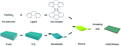
Results and discussion
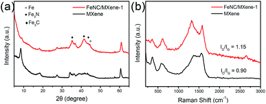
The synthetic strategy of the FeNC/MXene hybrid nanosheet is illustrated in Scheme 1. Iron precursor (ferrous acetate) and nitrogen ligand (1,10-phenanthroline monohydrochloride monohydrate) were first mixed in the ethanol to form an iron–ligand complex. Subsequently, MXene nanosheets were added and a uniform layer of iron complex was coated on the MXene surface. After a heat treatment in the inert atmosphere, FeNC/MXene hybrid nanosheet was synthesized with the FeNC layer closely attached on the surface of each MXene (will be demonstrated later).The structure of FeNC/MXene hybrid nanosheet was first investigated by X-ray diffractometer (XRD) and Raman analysis. Fig. 1a presents the XRD patterns, indicating the impregnation of FeNC into the MXene nanosheets. The XRD pattern of the pristine MXene displays a sharp peak at 8.4° and small peaks at 34.0°, 41.8°, 61.6°, which are assigned to the characteristic (002), (101), (105) and (110) planes, respectively, for Ti3C2Tx MXene and thus confirmed the successfully synthesis of MXene nanosheets. However, the (002) peak almost disappeared in the XRD pattern of FeNC/MXene-1, replaced by four new broad peaks, centered at 35.2°, 43.8°, 41.3° and 44.7°, corresponding to (200) and (102) planes of Fe3C phase (JCPDS no. 65-2412), (002) plane of Fe3N (JCPDS no. 21-1276), and (110) plane of metallic iron (JCPDS no. 65-4899), respectively. It is speculated that the disappearance of (002) peak in FeNC/MXene-1 may be attributed to the wrecked lattice arrangement of MXene nanosheets and thus indicated the incorporation of FeNC into each single MXene nanosheet. It should be also note that the background of MXene XRD pattern is a bit rough, which is related with the exfoliation process resulting in a loss of diffraction signal in the out-of-plane direction and the nonplanar shape of MXene nanosheets leading to broadening of the peaks for in-plane diffraction.17
The Raman spectra in Fig. 1b shows two small bands at around 360 cm−1 and 600 cm−1, which were assigned to the vibrations of atoms in Ti3C2Tx MXene and thus indicative of MXene.26–29 Another two broad bands were detected at around 1369 and 1580 cm−1. The former (D-band) corresponds to disordered graphite from the defects in carbon-based materials, and the latter (G-band) is attributed to the vibration of sp2 hybridized carbon atoms in a 2D hexagonal lattice.30–33 A slight redshift of D band (about 47 cm−1) was observed from the pristine MXene to FeNC/MXene-1. The D band shift is a character of defects, which may be resulted from the high temperature treatment for MXene34,35 or the structure changes related with the interaction between MXene and FeNC component. It is also worth noting that a slight change of the ID/IG value after the introduction of FeNC into MXene was detected. This value increased from 0.90 to 1.15, indicating more defect in the FeNC/MXene-1 than the pristine MXene.36
The morphology of the FeNC/MXene hybrid nanosheet was then characterized by the scanning electron microscopy (SEM) and transmission electron microscopy (TEM). The SEM images in Fig. 2 reveal that FeNC/MXene-1 remained the sheet structure as the pristine MXene. The pristine MXene presented the typical thin flakes (Fig. 2a and b), and FeNC/MXene-1 maintained the flake structure (Fig. 2c and d), with no obvious aggregation of MXene nanosheets and an apparent coating of FeNC particles on the MXene surface. Fig. 2d shows that the FeNC coating consisted of small stacked particles with a particle size of 20–80 nm, forming a unique FeNC and MXene hybrid nanosheet structure. This FeNC/MXene-1 morphology could render a sufficient surface area and the exposure of more catalytic active sites, which would favour a high electrocatalytic activity. TEM images in Fig. 3 further disclose the hybrid nanosheet structure of FeNC/MXene-1. The pristine MXene were translucent and smooth flakes (Fig. 3a), whereas massive particles were closely attached on the surface of single MXene nanosheet in FeNC/MXene-1, forming a rugged FeNC coating (Fig. 3b and c). The high resolution TEM image indicates that these FeNC particles were crystalline with a lattice distance of 0.22 nm (Fig. 3d), which corresponded to the (002) plane of Fe3N phase and was consistent with the XRD result (Fig. 1a). In addition, high-angle annular dark-field scanning TEM (HAADF-STEM) images and the elemental mapping images were investigated (Fig. 3e), clearly confirming a uniform distribution of C, N, Fe, and Ti elements in the FeNC/MXene-1 hybrid nanosheet.
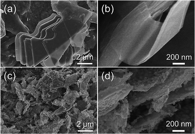 | ||
| Fig. 2 SEM images of the pristine MXene (a and b) and FeNC/MXene-1 (c and d) at different magnifications. | ||
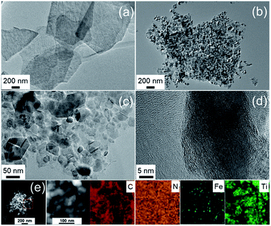 | ||
| Fig. 3 TEM images of the pristine MXene (a) and FeNC/MXene-1 (b–d). (e) HAADF-STEM images and the corresponding elemental maps of C, N, Fe, and Ti. | ||
A series of FeNC/MXene-x catalysts with different FeNC loadings were also prepared and investigated. As shown in Fig. S2 and S3,† SEM images reveal that all FeNC/MXene-x catalysts remained the flake structure, while the thickness of flakes increased with the increase of x value (higher FeNC loading). Note that the FeNC/MXene-5 was almost powdery with a flake thickness of around 200 nm (Fig. S2f and S3f†), which was much thicker than the flake thickness of FeNC/MXene-1 (less than 50 nm as shown in Fig. 2d). The TEM images (Fig. S4†) further demonstrated the hybrid nanosheet structure in all FeNC/MXene-x catalysts, with the FeNC particle coating closely attached on the MXene surface.
The nature of the porosity of the catalysts was performed by the nitrogen sorption analysis. As shown in Fig. 4a, the pristine MXene and FeNC/MXene-1 exhibited Type IV isotherms with obvious hysteresis loops, which were resulted from mesoporous voids between the nanosheets.30 The specific surface areas (SBET) were 35.6 m2 g−1 for the pristine MXene and 28.1 m2 g−1 for the FeNC/MXene-1, suggesting a slight increase of SBET after the inclusion of FeNC. Notably, FeNC/MXene-1 gave the highest SBET value in the FeNC/MXene-x series, as listed in Table S1,† which may be related with the slight differences of the morphologies of FeNC coatings (Fig. S2–4†). The pore size distribution was displayed in Fig. 4b, revealing the domination of mesopores with a pore size range of 2–14 nm.
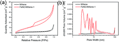 | ||
| Fig. 4 (a) Nitrogen sorption isotherms of the pristine MXene and FeNC/MXene-1. (b) Pore size distribution of the pristine MXene and FeNC/MXene-1. | ||
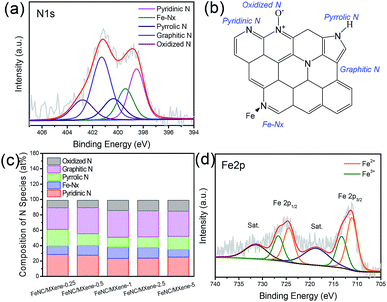
The X-ray photoelectron spectroscopy (XPS) was explored to investigate the elemental composition and surface state of the catalysts, with a N 2.7 at% and Fe 2.3 at% in the FeNC/MXene-1. It can be seen that the N content showed a highest value in FeNC/MXene-1 but a continuous increase trend for Fe contents with the increase of x in the FeNC/MXene-x catalysts (Table S2†), which indicated a maximum loading for the N element in the catalysts. The high resolution N1s spectrum of FeNC/MXene-1 was analysed and was deconvoluted into five species (Fig. 5a), centred at 398.5, 399.4, 400.4, 401.3 and 402.8 eV, and corresponded to the pyridinic nitrogen, Fe-Nx, pyrrolic nitrogen, graphitic nitrogen and oxidized nitrogen, respectively.12,37 A schematic model is shown in Fig. 5b to better understand the nitrogen configurations in the high resolution N1s of FeNC/MXene-1 catalyst. It is generally believed that the pyridinic nitrogen and Fe-Nx species contribute to the high ORR activity, while oxidized nitrogen is not significantly associated with the ORR performance and is unstable during the ORR operating.37 The percentage contents of different nitrogen species are listed in Table S3† and a comparison of nitrogen species in FeNC/MXene-x series is illustrated in Fig. 5c, revealing that the pyridinic nitrogen and graphitic nitrogen were the dominated configurations in all catalysts. It should be also noted that FeNC/MXene-1 exhibited the highest Fe-Nx content, with 14.95 at% in the total nitrogen (Table S3 and Fig. S5†), which may be responsible for its high ORR activity and will be discussed later. Furthermore, the XPS spectrum in Fe2p region was investigated (Fig. 5d, S6 and Table S4†), and was divided into Fe2+ 2p3/2 (711.2 eV), Fe3+ 2p3/2 (713.3 eV) and satellite (Sat., 718.5 eV).38,39 In combination with the XRD and XPS N1s results, it can be concluded that the Fe3+ species may be attributed to the Fe-Nx moieties in Fe3N phase and the Fe carbides in Fe3C phase.37
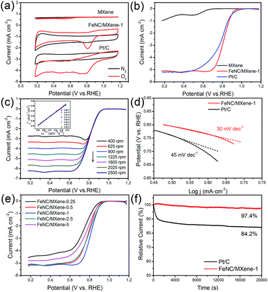
The ORR activities of the catalysts were first evaluated by cyclic voltammetry (CV) plots in N2- and O2-saturated 0.1 M KOH solution. As shown in Fig. 6a, obvious cathodic reduction current peaks were detected in the O2-saturated solution for all catalysts, whereas no peaks were observed in the N2-saturated solution. The cathodic reduction current peak of FeNC/MXene-1 was located at 0.81 V, which was much more positive than the pristine MXene (0.54 V) and the commercial Pt/C catalyst (0.79 V), indicating that FeNC/MXene-1 had a much better catalytic activity than the pristine MXene and the Pt/C. The linear sweep voltammogram (LSV) curves were subsequently performed in O2-saturated electrolyte (Fig. 6b). FeNC/MXene-1 exhibited a better ORR activity with an onset potential (Eonset) of 1.00 V, much more positive than the pristine MXene (0.71 V) and comparable to the Pt/C (1.03 V, Fig. S7†). More importantly, FeNC/MXene-1 displayed a half-wave potential (E1/2) of 814 mV, which was 25 mV higher than the Pt/C (789 mV), indicating that FeNC/MXene-1 processed a higher ORR activity than the Pt/C catalyst. Table S6† shows a comparison of electrocatalytic ORR performance with other FeNC-based catalysts, which demonstrated the comparable electrocatalytic activity when using MXene as the support than the carbon support.
To investigate the ORR kinetic characteristics, the LSV curves of FeNC/MXene-1 under different rotating rates were studied, revealing that the limiting current densities increased with the increase of rotating rates (Fig. 6c). The corresponding Koutecky–Levich (K–L) plots (inset in Fig. 6c) determined from the LSV curves disclosed the linear relationships and the first-order reaction kinetics.35 The transfer electron numbers calculated by the K–L plots was 3.9–4.0 from a potential range of 0.2–0.4 V, which indicated a direct four electron reduction pathway for the FeNC/MXene-1. The Tafel plot in Fig. 6d further demonstrated the good electron transfer channels in the FeNC/MXene hybrid nanosheet. The Tafel slope of FeNC/MXene-1 is 30 mV dec−1, which was much smaller than the Pt/C (45 mV dec−1), suggesting a faster electron transfer rate in FeNC/MXene-1 than the Pt/C.
In addition, the electrocatalytic performances of FeNC/MXene-x series were also investigated (Fig. 6e), and all FeNC/MXene-x catalysts exhibited the Pt-comparable onset potentials (Table S5†). On the basis of the above results (Fig. 2 and 5), we believe that the superior catalytic activity of FeNC/MXene-x can be contributed to the MXene support which rendered a two-dimensional platform with excellent electronic channels and to the rugged FeNC coating with sufficient exposure of ORR active centres. However, FeNC/MXene-x presented obvious differences on the E1/2 values, with the best performance in FeNC/MXene-1 (Table S5†). Obviously, there is an optimum FeNC loading to prepare the FeNC/MXene with the most positive E1/2. The XPS results (Tables S2 and S3†) disclosed that FeNC/MXene-x reached the highest N contents when x = 1 and 2.5, indicating a maximum N loading, and the FeNC/MXene-1 processed the highest Fe-Nx species than the other catalysts. Therefore, it is speculated that the ORR activity was strongly related with the nitrogen contents as well as nitrogen species (mainly Fe-Nx configuration) in these FeNC/MXene-x catalysts.
The electrochemical durability is also a pivotal issue in evaluating the ORR performances of catalysts. A current–time response of FeNC/MXene-1 and Pt/C in O2-saturated solution was carried out in O2-saturated 0.1 M KOH solution over a 20![[thin space (1/6-em)]](https://www.rsc.org/images/entities/char_2009.gif) 000 s continuous time at a rotating rate of 1000 rpm, as shown in Fig. 6f. Impressively, the FeNC/MXene-1 demonstrated a superior durability, with only 2.6% decay after a 20
000 s continuous time at a rotating rate of 1000 rpm, as shown in Fig. 6f. Impressively, the FeNC/MXene-1 demonstrated a superior durability, with only 2.6% decay after a 20![[thin space (1/6-em)]](https://www.rsc.org/images/entities/char_2009.gif) 000 s continuous test, much better than the Pt/C catalyst with a current loss of up to 15.8%. It is worth noting that this durability is better than the reported FePc/Ti3C2Tx work (retain 74% over 5000 s) using the multilayered Ti3C2Tx as the support.16 The metal-Nx macrocycles (FePc) is generally considered to display a high ORR activity but poor durability due to the unstable structure of macrocycles.7 The ultrahigh stability of FeNC/MXene-1 in this work could be related with the graphitization of catalyst after the pyrolysis process.7 Compare with other FeNC-base catalysts, the ORR durability of FeNC/MXene-1 is comparable with the carbon-supported FeNC composite catalysts,11,14,16,39–41 as listed in Table S7,† making MXene an excellent support material for ORR catalysts. The excellent durability of FeNC/MXene-1 is speculated to the attribution of highly conductive channels and less agglomeration of FeNC particles due to the presence of MXene support, making MXene as an excellent candidate to replace carbon supports. In addition, a 10
000 s continuous test, much better than the Pt/C catalyst with a current loss of up to 15.8%. It is worth noting that this durability is better than the reported FePc/Ti3C2Tx work (retain 74% over 5000 s) using the multilayered Ti3C2Tx as the support.16 The metal-Nx macrocycles (FePc) is generally considered to display a high ORR activity but poor durability due to the unstable structure of macrocycles.7 The ultrahigh stability of FeNC/MXene-1 in this work could be related with the graphitization of catalyst after the pyrolysis process.7 Compare with other FeNC-base catalysts, the ORR durability of FeNC/MXene-1 is comparable with the carbon-supported FeNC composite catalysts,11,14,16,39–41 as listed in Table S7,† making MXene an excellent support material for ORR catalysts. The excellent durability of FeNC/MXene-1 is speculated to the attribution of highly conductive channels and less agglomeration of FeNC particles due to the presence of MXene support, making MXene as an excellent candidate to replace carbon supports. In addition, a 10![[thin space (1/6-em)]](https://www.rsc.org/images/entities/char_2009.gif) 000 cycles test with the potential from 0.6 to 1.0 V vs. RHE was also conducted (Fig. S8†), and FeNC/MXene-1 catalyst shows a 11 mV degradation of E1/2 after this 10
000 cycles test with the potential from 0.6 to 1.0 V vs. RHE was also conducted (Fig. S8†), and FeNC/MXene-1 catalyst shows a 11 mV degradation of E1/2 after this 10![[thin space (1/6-em)]](https://www.rsc.org/images/entities/char_2009.gif) 000-cycle-performance, which further demonstrated the remarkable stability of FeNC/MXene-1 catalyst. Moreover, the methanol crossover effect of FeNC/MXene-1 and Pt/C was carried out from the chronoamperometric curves followed by the injection of 3 M methanol into the electrolyte, as shown in Fig. S9.† We can see that FeNC/MXene-1 exhibited much better tolerance to methanol crossover stability after adding the methanol, with no obvious degradation of current. In comparison, Pt/C showed a significant decrease of current due to the oxidation of methanol.
000-cycle-performance, which further demonstrated the remarkable stability of FeNC/MXene-1 catalyst. Moreover, the methanol crossover effect of FeNC/MXene-1 and Pt/C was carried out from the chronoamperometric curves followed by the injection of 3 M methanol into the electrolyte, as shown in Fig. S9.† We can see that FeNC/MXene-1 exhibited much better tolerance to methanol crossover stability after adding the methanol, with no obvious degradation of current. In comparison, Pt/C showed a significant decrease of current due to the oxidation of methanol.
Conclusions
In summary, a novel FeNC/MXene hybrid nanosheet was for the first time synthesized using the highly-dispersed MXene nanosheet as the support. This FeNC/MXene hybrid nanosheet not only exhibited a more positive half-wave potential than the Pt/C catalyst, but more importantly displayed a superb durability with only 2.6% decay over a 20![[thin space (1/6-em)]](https://www.rsc.org/images/entities/char_2009.gif) 000 s continuous test. In combination with the structure and chemistry composition analysis, it is believed that the hybrid nanosheet structure and the Fe-Nx configurations mainly contribute to the superior catalytic activity of FeNC/MXene. In this hybrid structure, MXene serves as the catalyst support rendering a unique two-dimensional platform and excellent electronic channels, while the rugged FeNC coating closely attached on the surface of MXene provides sufficient ORR active centres, making it a good catalyst for electrocatalysis. This work may render a new insight into the rational design of non-precious metal catalysts using the MXene support.
000 s continuous test. In combination with the structure and chemistry composition analysis, it is believed that the hybrid nanosheet structure and the Fe-Nx configurations mainly contribute to the superior catalytic activity of FeNC/MXene. In this hybrid structure, MXene serves as the catalyst support rendering a unique two-dimensional platform and excellent electronic channels, while the rugged FeNC coating closely attached on the surface of MXene provides sufficient ORR active centres, making it a good catalyst for electrocatalysis. This work may render a new insight into the rational design of non-precious metal catalysts using the MXene support.
Conflicts of interest
There are no conflicts to declare.Acknowledgements
This work was financially supported by Science Foundation of China University of Petroleum, Beijing (No. 2462017YJRC013).Notes and references
- F. Cheng and J. Chen, Chem. Soc. Rev., 2012, 41, 2172–2192 RSC.
- J. Suntivich, H. A. Gasteiger, N. Yabuuchi, H. Nakanishi, J. B. Goodenough and Y. Shao-Horn, Nat. Chem., 2011, 3, 546–550 CrossRef CAS PubMed.
- Y. Nie, L. Li and Z. Wei, Chem. Soc. Rev., 2015, 44, 2168–2201 RSC.
- M. Shao, Q. Chang, J. P. Dodelet and R. Chenitz, Chem. Rev., 2016, 116, 3594–3657 CrossRef CAS PubMed.
- H. Li, J. Yang, M. Gao, J. Wang and B. Sun, Food Chem., 2019, 271, 388–392 CrossRef CAS PubMed.
- L. Dai, Y. Xue, L. Qu, H. J. Choi and J. B. Baek, Chem. Rev., 2015, 115, 4823–4892 CrossRef CAS PubMed.
- C. W. B. Bezerra, L. Zhang, K. Lee, H. Liu, A. L. B. Marques, E. P. Marques, H. Wang and J. Zhang, Electrochim. Acta, 2008, 53, 4937–4951 CrossRef CAS.
- S. Ratso, N. R. Sahraie, M. T. Sougrati, M. Kaarik, M. Kook, R. Saar, P. Paiste, Q. Jia, J. Leis, S. Mukerjee, F. Jaouen and K. Tammeveski, J. Mater. Chem. A, 2018, 6, 14663–14674 RSC.
- N. Daems, X. Sheng, I. F. J. Vankelecom and P. P. Pescarmona, J. Mater. Chem. A, 2014, 2, 4085–4110 RSC.
- G. A. Ferrero, K. Preuss, A. B. Fuertes, M. Sevilla and M. M. Titirici, J. Mater. Chem. A, 2016, 4, 2581–2589 RSC.
- W. Wang, W. Chen, P. Miao, J. Luo, Z. Wei and S. Chen, ACS Catal., 2017, 7, 6144–6149 CrossRef CAS.
- W. J. Jiang, L. Gu, L. Li, Y. Zhang, X. Zhang, L. J. Zhang, J. Q. Wang, J. S. Hu, Z. Wei and L. J. Wan, J. Am. Chem. Soc., 2016, 138, 3570–3578 CrossRef CAS PubMed.
- D. Villers, X. Jacques-Bedard and J. P. Dodelet, J. Electrochem. Soc., 2004, 151, A1507–A1515 CrossRef CAS.
- H. Yin, C. Zhang, F. Liu and Y. Hou, Adv. Funct. Mater., 2014, 24, 2930–2937 CrossRef CAS.
- H. R. Byon, J. Suntivich and Y. Shao-Horn, Chem. Mater., 2011, 23, 3421–3428 CrossRef CAS.
- Z. Li, Z. Zhuang, F. Lv, H. Zhu, L. Zhou, M. Luo, J. Zhu, Z. Lang, S. Feng, W. Chen, L. Mai and S. Guo, Adv. Mater., 2018, 30, 1803220 CrossRef PubMed.
- M. Naguib, M. Kurtoglu, V. Presser, J. Lu, J. Niu, M. Heon, L. Hultman, Y. Gogotsi and M. W. Barsoum, Adv. Mater., 2011, 23, 4248–4253 CrossRef CAS PubMed.
- M. Naguib, V. N. Mochalin, M. W. Barsoum and Y. Gogotsi, Adv. Mater., 2014, 26, 992–1005 CrossRef CAS PubMed.
- O. Mashtalir, M. R. Lukatskaya, M. Q. Zhao, M. W. Barsoum and Y. Gogotsi, Adv. Mater., 2015, 27, 3501–3506 CrossRef CAS PubMed.
- D. Xiong, X. Li, Z. Bai and S. Lu, Small, 2018, 14, 1703419 CrossRef PubMed.
- L. Zhao, B. Dong, S. Li, L. Zhou, L. Lai, Z. Wang, S. Zhao, M. Han, K. Gao, M. Lu, X. Xie, B. Chen, Z. Liu, X. Wang, H. Zhang, H. Li, J. Liu, H. Zhang, X. Huang and W. Huang, ACS Nano, 2017, 11, 5800–5807 CrossRef CAS PubMed.
- J. Ran, G. Gao, F. T. Li, T. Y. Ma, A. Du and S. Z. Qiao, Nat. Commun., 2017, 8, 13907 CrossRef CAS PubMed.
- Q. Zhang, J. Teng, G. Zou, Q. Peng, Q. Du, T. Jiao and J. Xiang, Nanoscale, 2016, 8, 7085–7093 RSC.
- F. Shahzad, M. Alhabeb, C. B. Hatter, B. Anasori, S. M. Hong, C. M. Koo and Y. Gogotsi, Science, 2016, 353, 1137–1140 CrossRef CAS PubMed.
- Y. Wen, T. E. Rufford, X. Chen, N. Li, M. Lyu, L. Dai and L. Wang, Nano Energy, 2017, 38, 368–376 CrossRef CAS.
- L. Zhang, W. Su, Y. Huang, H. Li, L. Fu, K. Song, X. Huang, J. Yu and C. T. Lin, Nanoscale Res. Lett., 2018, 13, 343 CrossRef PubMed.
- T. Hu, M. Hu, Z. Li, H. Zhang, C. Zhang, J. Wang and X. Wang, J. Phys. Chem. A, 2015, 119, 12977–12984 CrossRef CAS PubMed.
- T. Hu, J. Wang, H. Zhang, Z. Li, M. Hu and X. Wang, Phys. Chem. Chem. Phys., 2015, 17, 9997–10003 RSC.
- M. Hu, T. Hu, Z. Li, Y. Yang, R. Cheng, J. Yang, C. Cui and X. Wang, ACS Nano, 2018, 12, 3578–3586 CrossRef CAS PubMed.
- Y. Wen, T. E. Rufford, D. Hulicova-Jurcakova, X. Zhu and L. Wang, ACS Appl. Mater. Interfaces, 2016, 8, 18051–18059 CrossRef CAS PubMed.
- C. Yang, W. Que, Y. Tang, Y. Tian and X. Yin, J. Electrochem. Soc., 2017, 164, A1939–A1945 CrossRef CAS.
- Y. Tang, J. Zhu, W. Wu, C. Yang, W. Lv and F. Wang, J. Electrochem. Soc., 2017, 164, A923–A929 CrossRef CAS.
- C. Yang, W. Que, X. Yin, Y. Tian, Y. Yang and M. Que, Electrochim. Acta, 2017, 225, 416–424 CrossRef CAS.
- G. Freihofer, S. Raghavan and D. Gosztola, Appl. Spectrosc., 2013, 67, 321–328 CrossRef CAS PubMed.
- M. S. Dresselhaus, A. Jorio, A. G. Souza and R. Saito, Philos. Trans. R. Soc., A, 2010, 368, 5355–5377 CrossRef CAS PubMed.
- L. Lin, Q. Zhu and A. W. Xu, J. Am. Chem. Soc., 2014, 136, 11027–11033 CrossRef CAS PubMed.
- M. Q. Wang, W. H. Yang, H. H. Wang, C. Chen, Z. Y. Zhou and S. G. Sun, ACS Catal., 2014, 4, 3928–3936 CrossRef CAS.
- T. Yamashita and P. Hayes, Appl. Surf. Sci., 2008, 254, 2441–2449 CrossRef CAS.
- Q. Zuo, P. Zhao, W. Luo and G. Cheng, Nanoscale, 2016, 8, 14271–14277 RSC.
- C. Zhang, J. Liu, Y. Ye, Z. Aslam, R. Brydson and C. Liang, ACS Appl. Mater. Interfaces, 2018, 10, 2423–2429 CrossRef CAS PubMed.
- J. Cao, X. Jia, M. Guo, Y. Du, J. Xu and Z. Chen, Sustainable Energy Fuels, 2018, 2, 169–174 RSC.
Footnote |
| † Electronic supplementary information (ESI) available. See DOI: 10.1039/c9ra01330j |
| This journal is © The Royal Society of Chemistry 2019 |

