 Open Access Article
Electro-deposition of bactericidal and corrosion-resistant hydroxyapatite nanoslabs†
Manisha Sharmaab,
Rohit Nagara,
Vijay Kumar Meena*ab and
Suman Singh *ab
*ab
aCentral Scientific Instruments Organisation (CSIR-CSIO), Chandigarh, India. E-mail: ssingh@csio.res.in; vijaykumar@csio.res.in
bAcademy of Scientific and Innovative Research (AcSIR-CSIO), Ghaziabad, India
First published on 9th April 2019
Abstract
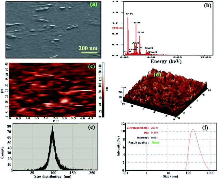
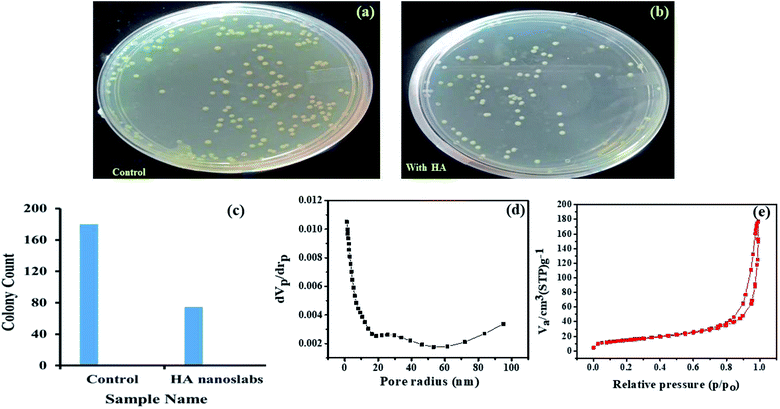
Herein, nanoscale hydroxyapatite (HA) with a slab-like morphology was synthesized, and its size was calculated to be in the range of 80–150 nm, as confirmed via scanning electron microscopy (SEM) and atomic force microscopy (AFM). The nanoscale HA with a slab-like structure has been referred as HA nanoslabs in the manuscript. The composition, crystallinity, wettability, bacterial resistance porosity, surface roughness and corrosion resistance of these HA nanoslabs were studied using energy dispersive spectroscopy (EDAX), X-ray diffraction (XRD), contact angle, colony count BET analyzer and profilometer and polarization techniques, respectively. The contact angle of the HA nanoslabs was found to be 22.6°, which indicated the hydrophilic nature of these nanoslabs. Their bacterial resistance was studied against the Salmonella typhi strain, and it was found that in the presence of the HA nanoslabs, the growth of the bacteria was hindered. For the corrosion resistance study, the HA nanoslabs were electro-deposited on a titanium alloy, used as a substrate. The deposition was carried out at varying currents, viz, 1 mA, 3 mA and 5 mA. The open circuit potential (OCP) and polarization were used for the estimation of the corrosion resistance of the bare and coated substrates. The corrosion potential started shifting towards noble potential, and the current density started decreasing with an increase in the electrochemical deposition current. This indicated good corrosion resistance of these nanoslabs.
1 Introduction
The market of orthopaedic devices is growing rapidly due to the improved economy, changed lifestyle and increased facility of health insurance. As orthopaedic devices, metal implants are being used for a long time to stabilize fractures, reduce pain or to restore joint functions. However, the success of an implant is highly dependent on some factors, such as its good biocompatibility, good mechanical properties etc. But generally, the implants fail due to infection or loosening caused by the corroded implant surface. This is mainly due to the fact that an implant is exposed to the hostile environment of living cells, tissues and biological fluids. This hostile environment makes the implant susceptible to localized corrosion in the human body or sometimes, the body considers it as a foreign entity and hence rejects it. In such cases, the surface modification of an implant material becomes important to reduce the chances of implant failure due to corrosion or infection.Since about 50% of the bone is made up of the inorganic mineral hydroxyapatite (HA), HA is being widely used as a bone replacement material in a variety of orthopedic implants and artificial prostheses or as a coating material to promote bone growth inside the prosthetic implants. A number of methods, viz, thermal spraying, plasma spraying, ion-beam deposition, laser ablation and electrochemical deposition, have been reported for the coating of hydroxyapatite on implants.1–5 Plasma spraying is the most commonly adopted technique for commercial HA coatings, however, it suffers from severe disadvantages such as poor adhesion, non-uniformity and possible degradation of hydroxyapatite due to the use of high temperatures during the coating process.6 On the other hand, the thermal spraying method suffers from the disadvantages of poor coating, poor substrate adherence, and non-uniform crystallinity. High sintering temperatures used in thermal spraying can also result in crack propagation on the coating surface.7 A review has been very well documented by Mohseni et al., who very comprehensively analyzed nine different techniques used for hydroxyapatite coating.8 Moreover, the advantages and disadvantages of these techniques were comprehensively discussed.
In recent years, due to the factors such as the requirement of low temperatures, the ability to control the coating thickness, the possibility to improve the substrate/coating bond strength using biocompatible linkers, the use of low cost equipment, the ease of experimentation, etc., much interest has evolved in electrodeposition. The coating properties and surface structures can be easily controlled via electrochemical deposition technique just by changing the parameters such as applied potential and current density, deposition time, electrolyte temperature, ionic concentration and pH values.9
In this study, the synthesis of nanoslabs of hydroxyapatite and their electrochemical deposition on an implant material substrate, i.e. Ti6Al4V, using the currents of 1 mA, 3 mA, and 5 mA is reported. Before conducting the electrochemical deposition process, the shape, size, composition, crystallinity, wettability, bacterial resistance and corrosion resistance of the HA nanoslabs were well studied using scanning electron microscopy (SEM), atomic force microscopy (AFM), energy dispersive spectroscopy (EDAX), X-ray diffraction (XRD), contact angle, colony count and polarization techniques, respectively. After coating the implant substrate with the HA nanoslabs, the corrosion resistance of the substrate increased, as proved via the polarization studies.
2 Experimentation
2.1 Materials
Hank's solution, sodium hydroxide (NaOH), diammonium hydrogen orthophosphate (NH4)2HPO4, N-cetyl-N,N,N trimethylammonium bromide (C19H42BrN), calcium chloride (CaCl2), sodium chloride (NaCl), potassium phosphate dibasic (K2HPO4), ethanol (C2H5OH), nutrient agar, and nutrient broth were obtained from Sigma Aldrich, now owned by Merck.2.2 Instrumentation
The Fourier transform infrared (FTIR) spectrum of the HA nanoslabs was obtained in the range of 400–4000 cm−1 using the Varian FTIR system (600 series, USA). The crystal structure of the nanoslabs was studied from their diffraction pattern, obtained using an X-ray diffractometer (XRD) from Bruker D8 Advance, Germany. The phase identification was achieved by comparing the sample diffraction pattern with the standard cards in the JCPDS database. The surface topology of the nanoslabs was observed by a field emission scanning electron microscope (FE-SEM), Model Quanta-200F coupled with an energy dispersive spectrometer, obtained from FEI, the Netherlands, which was used for elemental analysis. For the SEM studies, the samples were sputtered with gold for 60 s before imaging and examined at the accelerating voltage of 5 kV. The hydrophilicity of the HA nanoslabs was studied via the Kruss drop shape analysis system, Model DSA 100, using the sessile drop method. High-purity deionized water obtained via a Millipore water purifier was used for forming a drop on the surface to evaluate the wettability of the synthesized nanoslabs, and the measurements were conducted at room temperature. An atomic force microscopy (AFM) system, model XE-NSOM, Park Systems, Korea, was used for investigating the morphology and size distribution of the nanoslabs. The dynamic light scattering (DLS) studies were performed using a Zeta sizer obtained from Malvern. The surface area and porosity studies were performed on BET analyzer from Metrohm India Ltd., Model Belsorp Mini II. The pretreatment of samples was performed on Belprep-vac II analyzer. The electrodeposition and corrosion studies were performed using an electrochemical analyzer, Model CH1100, obtained from CHI instruments, USA. The corrosion studies of HA nanoslab-coated substrates were carried out using the Hank's solution as an electrolyte. The coated and uncoated Ti alloy was used as the working electrode, a platinum foil was used as an auxiliary electrode and Ag/AgCl was used as reference electrode. All studies were carried out at 37 °C. The surface roughness of the coated and uncoated implant material (Ti6Al4V) samples was measured using the Talysurf PGI 120 profilometer, where a Gaussian filter with a cut off of 0.8 mm was used. For bactericidal studies, incubation of the agar plates was conducted using a locally manufactured incubator. A gel doc system used for colony counting was obtained from Gold Sim, China. High-purity deionized water was used for the study, and the experiment was performed at room temperature.2.3 Methodology
![[thin space (1/6-em)]](https://www.rsc.org/images/entities/char_2009.gif) :
:![[thin space (1/6-em)]](https://www.rsc.org/images/entities/char_2009.gif) 1) mixture. Before electrodeposition, the solution was sonicated for 30 minutes to obtain a homogeneous suspension. The deposition was performed in three-electrode setup by applying the constant current of 1 mA, 3 mA, and 5 mA respectively. The setup consisted of the titanium plate as the working electrode, a platinum foil as the auxiliary electrode and Ag/AgCl as the reference electrode. The HA nanoslab suspension was stirred at a constant low stirring speed during the deposition process, and the pH of the solution was maintained at 6.5. The coated samples were sintered at 300 °C for 1 h under an inert atmosphere to increase the adhesion of the nanoslabs on the substrate.
1) mixture. Before electrodeposition, the solution was sonicated for 30 minutes to obtain a homogeneous suspension. The deposition was performed in three-electrode setup by applying the constant current of 1 mA, 3 mA, and 5 mA respectively. The setup consisted of the titanium plate as the working electrode, a platinum foil as the auxiliary electrode and Ag/AgCl as the reference electrode. The HA nanoslab suspension was stirred at a constant low stirring speed during the deposition process, and the pH of the solution was maintained at 6.5. The coated samples were sintered at 300 °C for 1 h under an inert atmosphere to increase the adhesion of the nanoslabs on the substrate.3 Results and discussion
3.1 Mechanism of the HA nanoslab formation
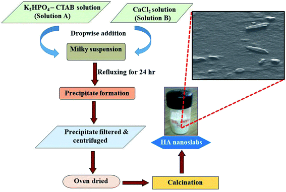
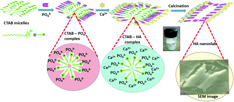
The exact mechanism of the formation of the HA nanoslabs is not fully known, but it is based on the expected reaction; the plausible mechanism has been depicted in a schematic shown in Fig. 2. The main facilitator for the formation of slab-like hydroxyapatite is CTAB. When dipotassium phosphate is added to the CTAB solution, the negatively charged phosphate ions are attracted towards the surface of the CTAB micelles due to electrostatic attraction between them.11 Both of them are stereo-chemically compatible to form a complex with each other due to their similar tetrahedral structure. The hexagonal complex micelle formed via the interaction of CTAB with phosphate ions might be acting as a nucleation center for the formation of hydroxyapatite.12 After the addition of the calcium source, the particles get crystallized on the surface of the CTA–PO4 micelle complex; thus, the CTA–HA complex is formed. After calcination of the CTA–HA complex, the surfactant gets removed, and a slab-like structure of hydroxyapatite is formed.3.2 Characterization of the hydroxyapatite nanoslabs (HA nanoslabs)
β(2θ) = Kλ/L![[thin space (1/6-em)]](https://www.rsc.org/images/entities/char_2009.gif) cos cos![[thin space (1/6-em)]](https://www.rsc.org/images/entities/char_2009.gif) θ θ |
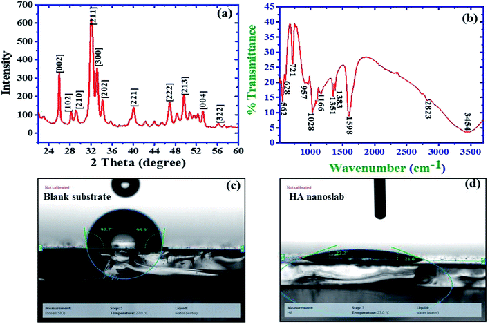 | ||
| Fig. 4 (a) XRD pattern of the HA nanoslabs. (b) FTIR spectrum of the HA nanoslabs. (c) Contact angle of the blank substrate. (d) Contact angle of the HA nanoslab-coated substrate. | ||
| 2θ | d (Å) | FWHM (°) | Plane | Crystallites (nm) |
|---|---|---|---|---|
| 26.0 | 3.188 | 0.3 | 002 | 21.84 |
| 28.16 | 3.168 | 0.3 | 102 | 28.53 |
| 29.12 | 3.080 | 0.7 | 210 | 12.25 |
| 31.9 | 2.820 | 0.83 | 211 | 10.4 |
| 33.13 | 2.692 | 0.6 | 300 | 14.43 |
| 34.21 | 2.619 | 0.6 | 202 | 14.48 |
| 40.08 | 2.264 | 0.95 | 221 | 9.3 |
| 46.9 | 1.974 | 0.9 | 222 | 10.05 |
The XRD data was also used to calculate the preference, which was used as a structure indicator. The preference is defined as the difference of RI from RIs:
| P = (RI − RIs)/RIs |
The relative intensity (RI) of the (002) peak as compared to that of the three strongest peaks for the standard powder HA sample (JCPDS 9432) is defined as RI = I(002)/I(211) + I(112) + I(300), where I(002), I(211), I(112), and I(300) are the intensities of the respective plane peaks. For the standard HA powder, the RI as calculated from JCPDS 9432 was found to be 0.182.13 The calculated value for the preference growth for the 002 plane was 2.36. Zanin et al.13 for their HA-graphene oxide composite found value of 2.61 for their preference growth along 022 plane.
Surface roughness is one of the most important topographical parameters influencing the cell–material interaction. The surface roughness in the range from 10 nm to 10 μm may influence the interface biology since it is of the same order in size as that of small cells and large biomolecules. Keeping this in mind, the surface roughness was also monitored for the samples deposited at different currents viz 1 mA, 3 mA, and 5 mA. The achieved roughness of the substrates coated with nano-HA synthesized at 1 mA was 3.74 × 10⁻² μm, which continued to decrease as the deposition current increased. The surface roughness value reached 1.68 × 10⁻² μm for 5 mA current density. For metals with the ability to form a passive layer, a decrease in the surface roughness increases the corrosion resistance.28–30 This type of corrosion behavior has been reported for materials such as copper, nickel, aluminum, stainless steel, magnesium and titanium alloys. This concludes that the substrates electrolytically coated with HA at higher currents produced more corrosion resistive surfaces.
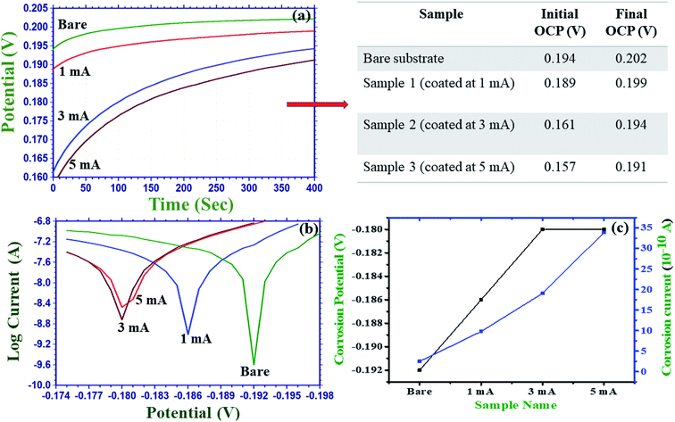
3.2.7.1 Open circuit potential study. Fig. 6(a) shows the open circuit potentials (OCP) obtained using the uncoated titanium alloy (bare substrate) and the coated substrates in the Hank's solution at room temperature. An OCP is the potential measured when no [net] current is flowing. As compared to that of the bare substrate, the OCP of the coated samples showed a shift towards the noble direction; this indicated the formation of an interface between the HA nanoslabs and the titanium alloy surface.31 The initial OCP of the bare substrate was 0.194 V, which reached 0.202 V after about 250 seconds and remained constant for about 400 s. The associated table in Fig. 6(a) shows the values of the OCP obtained initially and after 400 s for the bare and the HA nanoslab-coated substrates. In all the cases, the initial OCP increased with time. The shift of the OCP towards noble behavior w.r.t time for the electrolytically coated substrates as compared to the case of the bare substrate can be due to the porous nature of hydroxyapatite. As a result, the electrolyte enters the coating through the pores.31 From the values of the OCP, it is concluded that the HA nanoslabs deposited at the constant current of 5 mA are most robust in terms of corrosion resistance.
3.2.7.2 Corrosion studies. After being implanted in the body, the surface of an implant comes in contact with the biological fluids, interaction with which may involve changes in the local environment such as pH and ion concentrations. This leads to the loss of integrity. Therefore, the development of biomaterials that are resistant to corrosion is of prime importance. Herein, a corrosion resistant study was performed for the HA nanoslab-coated titanium alloy as the bioactivity and osteo-conductivity depend on the passivity of the coating. The corrosion mechanism involves two steps: the production of hydrogen ions (H+) and the dissolution of HA in H+ at high concentration. The production of hydrogen ions decreases the local pH at the sample–solution interface. This leads to high dissolution of the apatite coating.
Fig. 6(b and c) show the results obtained for the polarization curves, acquired using the uncoated and coated substrates. For the control substrate, bare titanium alloy was used. The figure showed that all the coated substrates showed better corrosion resistance as compared to the bare Ti6Al4V alloy substrate. The corrosion potential started shifting towards the noble potential, and the current density started decreasing in magnitude with an increase in the electrochemical deposition current. As is well-known, an electropositive corrosion potential and a low corrosion current density indicate good corrosion resistance. Therefore, this trend confirms the corrosion resistance behaviour of the coated substrates. The corrosion potential for the substrates coated at 3 and 5 mA is, however, the same. These results are in agreement with those of the roughness and OCP studies.
4 Conclusion
The CTAB-mediated synthesis of nanoscaled hydroxyapatite resulted in the formation of a slab-like morphology with sharp edges, a plausible mechanism of which is discussed. The average size of the HA-nanoslabs was in the range of 80–150 nm. Hydroxyapatite finds its application in the biomedical domain, especially as a coating material for an implant surface. The coating material should be bacterial resistant as the rejection of an implant surface by the body may result in infection and thus in the loosening of an implant, and a revision surgery may be required. Moreover, the environment inside the body is full of fluids of various types. These fluids might cause corrosion of the implanted implant. Considering these facts, the motive of this study was to synthesize a bacterial- and corrosion-resistant material. The HA nanoslabs showed both bacterial and corrosion resistance. Researchers have used different combinations with hydroxyapatite to induce bacterial resistance; however, in this study, the HA nanoslabs themselves showed bacterial resistance. This might be due to the presence of CTAB during their synthesis or the sharp edges of the slab morphology. The exact mechanism needs to be explored.Conflicts of interest
Authors don't have any conflict of interest.Acknowledgements
Authors are thankful to the Director, CSIR-Central Scientific Instruments Organisation (CSIR-CSIO), for motivating us to carry out this research. M. S. also acknowledges the Department of Science and Technology (DST), New Delhi, for providing the SYST fellowship. Authors also acknowledge the help of M/s Metrohm India Limited, Chandigarh for extending their help for BET studies.References
- T. J. Levingstone, et al., Plasma sprayed hydroxyapatite coatings: Understanding process relationships using design of experiment analysis, Surf. Coat. Technol., 2015, 283, 29–36 CrossRef CAS.
- J.-M. Choi, H.-E. Kim and I.-S. Lee, Ion-beam-assisted deposition (IBAD) of hydroxyapatite coating layer on Ti-based metal substrate, Biomaterials, 2000, 21(5), 469–473 CrossRef CAS PubMed.
- P. Cheang and K. A. Khor, Thermal spraying of hydroxyapatite (HA) coatings: Effects of powder feedstock, J. Mater. Process. Technol., 1995, 48(1), 429–436 CrossRef.
- G. Bolelli, et al., Suspension thermal spraying of hydroxyapatite: Microstructure and in vitro behaviour, Mater. Sci. Eng., 2014, 34, 287–303 CrossRef CAS PubMed.
- M. Hamdi and A. Ide-Ektessabi, Preparation of hydroxyapatite layer by ion beam assisted simultaneous vapor deposition, Surf. Coat. Technol., 2003, 163–164, 362–367 CrossRef CAS.
- R. J. Talib and M. R. M. Toff, Plasma-sprayed coating of hydroxyapatite on metal implants--a review, Med. J. Malays., 2004, 59, 153–154 Search PubMed.
- C. M. Roome and C. D. Adam, Crystallite orientation and anisotropic strains in thermally sprayed hydroxyapatite coatings, Biomaterials, 1995, 16(9), 691–696 CrossRef CAS PubMed.
- E. Mohseni, E. Zalnezhad and A. R. Bushroa, Comparative investigation on the adhesion of hydroxyapatite coating on Ti–6Al–4V implant: A review paper, Int. J. Adhes. Adhes., 2014, 48, 238–257 CrossRef CAS.
- A. Vladescu, et al., Influence of the electrolyte's pH on the properties of electrochemically deposited hydroxyapatite coating on additively manufactured Ti64 alloy, Sci. Rep., 2017, 7(1), 16819 CrossRef PubMed.
- J. M. Coelho, J. A. Moreira, A. Almeida and F. J. Monteiro, Synthesis and characterization of HAp nanorods from a cationic surfactant template method, J. Mater. Sci.: Mater. Med., 2010, 21(9), 2543–2549 CrossRef CAS PubMed.
- Y. Li, W. Tjandra and K. C. Tam, Synthesis and characterization of nanoporous hydroxyapatite using cationic surfactants as templates, Mater. Res. Bull., 2008, 43(8), 2318–2326 CrossRef CAS.
- G. Verma, K. C. Barick, N. Manoj, A. K. Sahu and P. A. Hassan, Rod-like micelle templated synthesis of porous hydroxyapatite, Ceram. Int., 2013, 39(8), 8995–9002 CrossRef CAS.
- H. Zanin, et al., Fast preparation of nano-hydroxyapatite/superhydrophilic reduced graphene oxide composites for bioactive applications, J. Mater. Chem. B, 2013, 1(38), 4947–4955 RSC.
- Q. Li, et al., In vitro synthesis of bioactive hydroxyapatite using sodium hyaluronate as a template, J. Mater. Chem., 2012, 22(38), 20257–20265 RSC.
- M. C. Chang and J. Tanaka, FT-IR study for hydroxyapatite/collagen nanocomposite cross-linked by glutaraldehyde, Biomaterials, 2002, 23(24), 4811–4818 CrossRef CAS PubMed.
- A. Antonakos, E. Liarokapis and T. Leventouri, Micro-Raman and FTIR studies of synthetic and natural apatites, Biomaterials, 2007, 28(19), 3043–3054 CrossRef CAS PubMed.
- J. Ryu, et al., Mussel-Inspired Polydopamine Coating as a Universal Route to Hydroxyapatite Crystallization, Adv. Funct. Mater., 2010, 20(13), 2132–2139 CrossRef CAS.
- C. Rey, et al., The carbonate environment in bone mineral: A resolution-enhanced fourier transform infrared spectroscopy study, Calcif. Tissue Int., 1989, 45(3), 157–164 CrossRef CAS PubMed.
- Y. Deng, et al., Biomimetic synthesis and biocompatibility evaluation of carbonated apatites template-mediated by heparin, Mater. Sci. Eng., 2013, 33(5), 2905–2913 CrossRef CAS PubMed.
- T. Ishizaki, N. Saito and O. Takai, Correlation of Cell Adhesive Behaviors on Superhydrophobic, Superhydrophilic, and Micropatterned Superhydrophobic/Superhydrophilic Surfaces to Their Surface Chemistry, Langmuir, 2010, 26(11), 8147–8154 CrossRef CAS PubMed.
- D. P. Dowling, et al., Effect of Surface Wettability and Topography on the Adhesion of Osteosarcoma Cells on Plasma-modified Polystyrene, J. Biomater. Appl., 2011, 26(3), 327–347 CrossRef CAS PubMed.
- S. Irani, M. Zandi, N. Salamian, S. M. Saeed, M. D. Joupari and S. M. Atyabi, The study of P19 stem cell behavior on aligned oriented electrospun poly(lactic-co-glycolic acid) nano-fibers for neural tissue engineering, Polym. Adv. Technol., 2014, 25(5), 562–567 CrossRef CAS.
- C. Vasilescu, et al., Characterisation and corrosion resistance of the electrodeposited hydroxyapatite and bovine serum albumin/hydroxyapatite films on Ti–6Al–4V–1Zr alloy surface, Corros. Sci., 2011, 53(3), 992–999 CrossRef CAS.
- K. S. W. Sing, D. H. Everett, R. A. W. Haul, L. Moscou, R. A. Pierotti, J. Rouquerol and T. Siemieniewska, Reporting physiorption data for gas/solid systems with Special Reference to the Determination of Surface Area and Porosity, Pure Appl. Chem., 1985, 57, 603–619 CAS.
- C. K. Poh, et al., In vitro characterizations of mesoporous hydroxyapatite as a controlled release delivery device for VEGF in orthopedic applications, J. Biomed. Mater. Res., Part A, 2012, 100(11), 3143–3150 CrossRef PubMed.
- G. F. Andrade, et al., An in situ synthesis of mesoporous SBA-16/hydroxyapatite for ciprofloxacin release: in vitro stability and cytocompatibility studies, J. Mater. Sci.: Mater. Med., 2014, 25(11), 2527–2540 CrossRef CAS PubMed.
- X. Wu, et al., Preparation of Mesoporous Nano-Hydroxyapatite Using a Surfactant Template Method for Protein Delivery, J. Bionic Eng., 2012, 9(2), 224–233 CrossRef.
- M. Cabrini, A. Cigada, G. Rondell and B. Vicentini, Effect of different surface finishing and of hydroxyapatite coatings on passive and corrosion current of Ti6Al4V alloy in simulated physiological solution, Biomaterials, 1997, 18(11), 783–787 CrossRef CAS PubMed.
- R. Walter and M. B. Kannan, Influence of surface roughness on the corrosion behaviour of magnesium alloy, Mater. Des., 2011, 32(4), 2350–2354 CrossRef CAS.
- R. B. Alvarez, H. J. Martin, M. F. Horstemeyer, M. Q. Chandler, N. Williams, P. T. Wang and A. Ruiz, Corrosion relationships as a function of time and surface roughness on a structural AE44 magnesium alloy, Corros. Sci., 2010, 52(5), 1635–1648 CrossRef CAS.
- S. G. Mohamed, A. A. Abdeltawab and M. A. Shoeib, Corrosion behaviour and bioactivity of electrophoretically deposited hydroxyapatite on titanium in physiological media (Hanks' solution), Mater. Sci., 2012, 30(3), 231–239 CAS.
Footnote |
| † Electronic supplementary information (ESI) available. See DOI: 10.1039/c9ra00811j |
| This journal is © The Royal Society of Chemistry 2019 |

