DOI:
10.1039/C9RA00317G
(Paper)
RSC Adv., 2019,
9, 9546-9554
Effects of temperature and pore structure on the release of methane in zeolite nanochannels
Received
14th January 2019
, Accepted 14th March 2019
First published on 26th March 2019
Abstract
In this work, we investigate the effects of temperature and pore size on the release of methane in zeolite nanochannels through molecular dynamics (MD) simulations. The methane release percentage at different temperatures and for different zeolite structures is calculated. In all-silica MFI (silicalite-1) zeolite, it is found that the release percentage increases with increasing temperature roughly at a constant rate when the temperature is below 598 K. For higher temperatures, the release percentage reaches about 90% and remains almost constant. For other structures, the release percentage is greatly affected by the average pore size. The release percentage is determined by the temperature and energy barrier inside the pores. Based on the energy barriers obtained in MD simulations, theoretical predictions of the release percentage are made, which are in good agreement with numerical results.
1. Introduction
Shale gas, which is predominantly composed of methane, is an important, eco-friendly energy resource. Whether shale gas can change the energy roadmap or not depends on the production cost. In the past decade, with the advances in various technologies, such as hydraulic fracturing and horizontal drilling, mass production of shale gas has been greatly promoted. As shale gas is confined in organic-rich, nanoscale shale formations, which are of very low permeability,1 the development of shale gas is much more difficult than that of conventional natural gases. Furthermore, the output of a typical shale gas well usually experiences a significant drop after three years.2,3 Therefore, it is important to understand the transport mechanisms of shale gas/methane in nanoconfinements and find new ways to enhance the release of methane from nanopores. This may lead to significant changes to the energy consumption landscape.
For shale gas, methane is primarily in the form of adsorbed gas and free gas in nanostructures.4 The former is adsorbed on the surfaces of nanoconfinements and the latter is stored in interconnected nanopore structures.5–7 In the literature, many studies on gas adsorption and desorption in nanostructures, such as nanopores, carbon nanotubes and nanochannels,8–10 have been conducted. Rexer et al.6 experimentally studied the adsorption of methane in an alum shale sample at various temperatures and pressures corresponding to the real geological conditions. They measured and modeled the methane excess uptake and isosteric enthalpy. Their analyses are helpful for understanding the storage mechanisms of shale gas. Lithoxoos et al.8 examined the adsorption capacity of single-wall carbon nanotubes (SWCNTs) at room temperature under different pressures through experiments and computations. They obtained density profiles of different gases and found that almost all the gas molecules are distributed near the pore walls. Zhu and Zhao9 investigated the mechanisms of methane adsorption in carbon nanopores through molecular dynamics (MD) simulations and theoretical analyses. It was found that the storage capacity of CNT is greatly enhanced compared with the bulk phase. The amount of methane molecules that can be stored in CNT at 20 bar is as much as that in the bulk phase at 220 bar. In addition, they found that there exists an optimal CNT diameter that maximizes the adsorption and developed the equation of state for adsorbed methane. Wu et al.11 also explored the mechanisms of methane adsorption and displacement processes in carbon nanochannels using MD simulations and obtained similar results to those of Zhu and Zhao.9 They found that when the external pressure reaches 5 MPa, the adsorption isotherms for bulk methane is about 1.5 mmol cm−3, whereas the adsorption isotherms of methane in silt pores is about 10 mmol cm−3.
In addition to gas adsorption, gas desorption in nanopores has also been studied. Yu and Sepehrnoori12 numerically investigated the gas desorption for five different shale formations. They analyzed the factors promoting gas desorption and the negative effects of geomechanics on gas production. Shabro et al.13 implemented a new 1D radial model to examine the transport mechanisms of shale gases and to forecast gas production in shale-gas reservoirs. Ho et al.3 examined the pressure effects on the methane release in kerogen and found that the release of free gas is driven by pressure gradients, while the adsorbed gas is controlled by gas desorption and diffusion.
Other than pressure and pore size, temperature also plays an important role in gas desorption as it determines the mean kinetic energy of gas molecules.14,15 Moreover, in different nanostructures, the potential distribution varies and can greatly affect the dynamics of molecules,16–18 and will certainly affect the release percentage. Unfortunately, little work has been carried out to study the influence of temperature and pore structure on the release of methane through nanopores.
This work investigates the effects of temperature and pore structure on the release of methane in zeolite nanopores through MD simulations. The methane release percentage is obtained at different temperatures for various zeolite structures. Herein, the zeolite structure is adopted to model shale pores. Zeolite is a traditional adsorbent, which has been widely used for gas storage, such as hydrogen and methane.19–21 Molecular dynamics simulation is employed to study the methane release in the nanochannels. For all-silica MFI zeolite, the release percentage increases to ∼90% with increasing temperature before T = 598 K, after which it rises mildly as temperature is further increased. The release of methane for different zeolite structures show that the release percentage of methane also greatly depends on the pore size. For zeolite with the average pore size of ∼3.5 Å (ABW zeolite), the release percentage rises from 0% to about 80% when the temperature is increased from 348 to 1148 K. For zeolite with relatively large pore size, 7.3 Å (CFI zeolite), the release percentage remains above 80% even at room temperature. The release percentage predicted using the energy barriers obtained from MD simulations shows good agreement with numerical results.
2. Molecular dynamics simulation
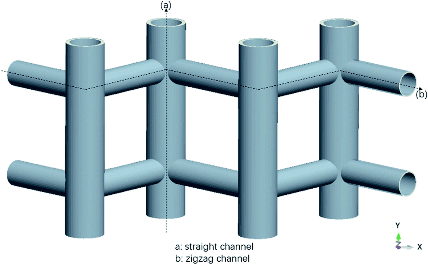
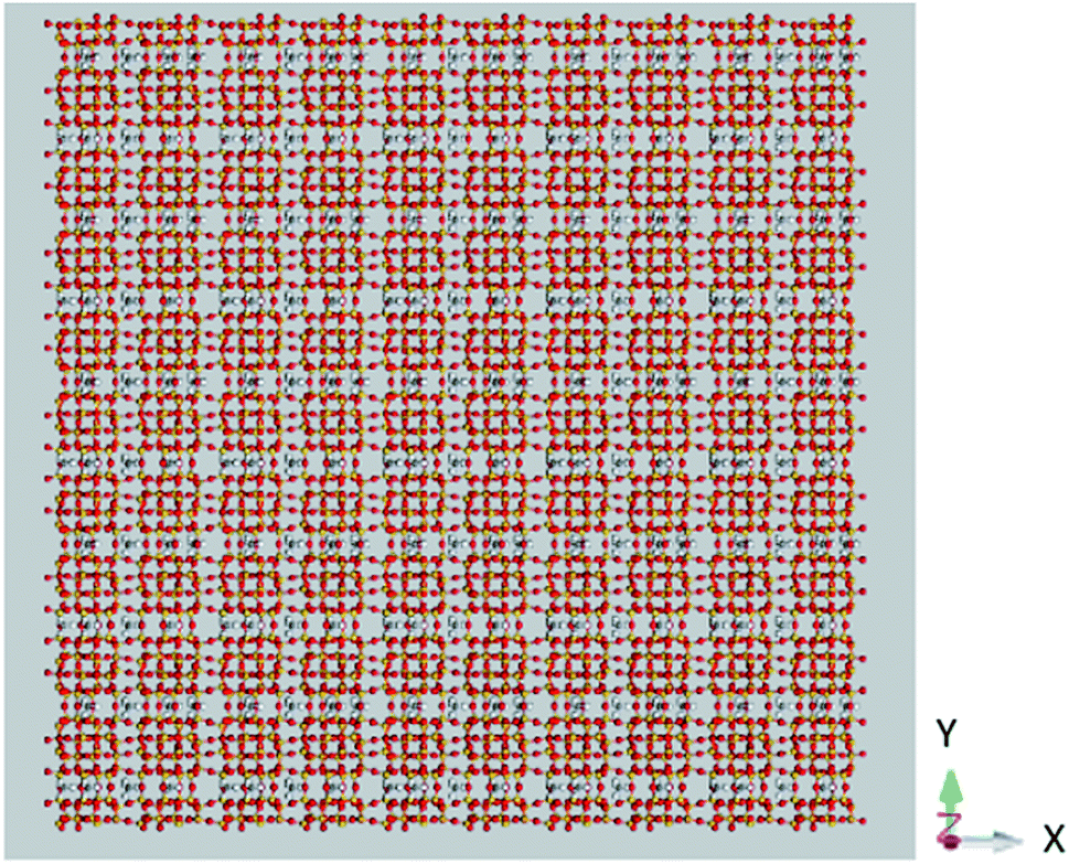
The MD simulations are performed using the commercial software, Material Studio. The nanoscale shale structures are modeled by zeolite nanochannels. The orthorhombic all-silica MFI zeolite (silicalite-1) of medium pore size is used as the major structure. The silicalite-1 structure has a three-dimensional network of interconnecting channels, containing both straight channels and zigzag channels, as illustrated in Fig. 1. The dimensions of a unit silicalite-1 cell are lx = 20.044 Å, ly = 19.918 Å, lz = 13.395 Å in the x, y, and z directions. Such a unit cell contains 96 SiO2 molecules and has a pore volume of 1.83 nm3.22 Fig. 2 shows different views of a silicalite-1 cell, where straight channels are in the y direction and zigzag channels are in the xz plane.
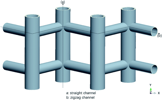 |
| | Fig. 1 Schematic of the zeolite pore structure illustrating straight and zigzag channels. | |
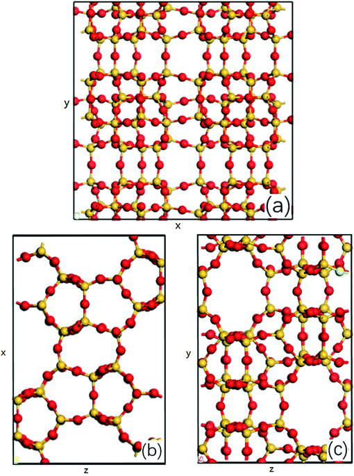 |
| | Fig. 2 (a) Main view, (b) top view and (c) left view of all-silica MFI zeolite structure, silicon atoms are represented by the yellow balls and oxygen atoms are represented by the red balls, x, y and z represent the edges of a unit cell in x, y and z direction. | |
In simulations, a zeolite containing five unit cells in the x and y directions and two unit cells in the z direction (totally 4800 SiO2 atoms) is considered, which is 100.22, 99.495, and 26.79 Å in the x, y, and z directions, as shown in Fig. 3. The lengths of the simulation system are 50, 50, and 2.68 nm in the x, y, and z directions with the zeolite at the center of the system. As periodic boundary conditions are applied in all the directions, such a configuration can eliminate the interactions between the zeolite and its images in the x and y directions and allows methane molecules to be released from the zeolite.
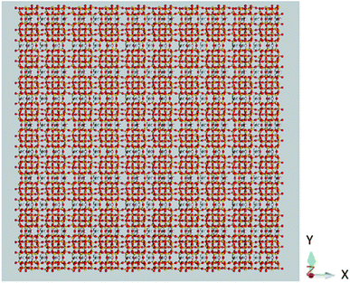 |
| | Fig. 3 A snapshot of the MD simulation system. | |
The DREIDING force field23 is used to model the zeolite, methane, and methane–zeolite interactions. The general potential for these interactions is given by
| |
 | (1) |
where
K0 is a force constant,
R0 and
θ0 are the equilibrium bond distance and angle,
B0 is the barrier height,
d0 is the phase factor,
n0 is the periodicity,
ε is the binding energy and
σ is the collision diameter,
rij is the separation between molecules/atom i and j,
θ is the bond angle,
ϕ is the bond torsion angle, and
q is the charge. The values of relevant parameters for various interactions are listed in
Table 1.
Table 1 Potential parameters for the force field
| Bond stretch parameters |
| Bond type |
K0 (kcal mol−1 Å−2) |
R0 (Å) |
| C–H |
700 |
1.09 |
| Si–O |
700 |
1.587 |
| Bond angle bend parameters |
| Bond type |
K0 (kcal mol−1 Å−2) |
θ0 |
| H–C–H |
100 |
109.471° |
| Si–O–Si |
100 |
104.51° |
| O–Si–O |
100 |
109.471° |
| Torsional parameters |
| Torsion type |
B0 (kcal mol−1) |
d0 |
n0 |
| O–Si–O–Si |
2 |
−1 |
3 |
| Lennard-Jones parameters |
| Interaction type |
σ (Å) |
ε (kcal mol−1) |
| H–H |
3.195 |
0.015 |
| C–C |
3.898 |
0.095 |
| H–C |
3.547 |
0.038 |
| H–O |
3.3 |
0.038 |
| H–Si |
3.733 |
0.069 |
| C–O |
3.651 |
0.095 |
| C–Si |
4.084 |
0.172 |
| Electrostatic parameters |
| Element type |
Charge (e) |
| C |
−0.572 |
| H |
0.143 |
| O |
−0.55 |
| Si |
1.1 |
The cut-off distance for the potential is 10.5 Å and the time step is 1 fs. The temperature of the system is maintained by the Berendsen thermostat.24 The pressure of the system is set at 20 MPa to simulate the geological condition of practical shale gas reservoirs.6 Under this pressure, the methane density at 350 K is determined as 119.41 kg m−3,25 which is used to disperse methane molecules in the system. The loading of methane is calculated based on this density from the equation of state25 according to the pore volume (1.83 nm3 per unit cell). Initially, both the free space outside and the pores inside the zeolite are filled with methane molecules according to this density. The molecules outside the zeolite are used to help make the conditions inside the zeolite similar to the real geological conditions of shale gases. The system is relaxed for 200 ps in the (N, V, T) ensemble. Then the methane molecules outside the zeolite are removed and the new system with methane inside the zeolite is performed in the (N, V, E) ensemble for calculating the release percentage, as shown in Fig. 3. Depending on the temperature of the system, the simulation time ranges from 4 to 45 ns, which is sufficiently long for the system to reach the steady state.
In addition to all-silica MFI zeolite, five other zeolite structures, i.e. ABW, VET, TER, CFI and OFF zeolites, are also considered, which have different pore sizes. The structural parameters of these zeolites are given in Table 2.26
Table 2 Structural parameters of various zeolite structures
| Zeolite structure |
Crystal system |
Cell size (x, y, and z directions) |
Channel size and direction |
| ABW |
Orthorhombic |
10.31 Å × 8.18 Å × 5.00 Å |
3.4 Å × 3.8 Å, z direction |
| TER |
Orthorhombic |
9.747 Å × 23.880 Å × 20.068 Å |
5.0 Å × 5.0 Å, x direction |
| 7.0 Å × 4.1 Å, y direction |
| MFI |
Orthorhombic |
20.044 Å × 19.918 Å × 13.395 Å |
5.1 Å × 5.5 Å, y direction |
| 5.3 Å × 5.6 Å, x direction |
| VET |
Tetragonal |
13.045 Å × 13.045 Å × 5.034 Å |
5.9 Å × 5.9 Å, z direction |
| OFF |
Hexagonal |
13.291 Å × 13.291 Å × 7.582 Å |
6.7 Å × 6.8 Å, z direction |
| CFI |
Orthorhombic |
13.674 Å × 5.022 Å × 25.4880 Å |
7.2 Å × 7.5 Å, y direction |
3. Results and discussion
The number of methane molecules released from the zeolites is obtained in the simulations and the release percentage is calculated, which is defined as| |
 | (2) |
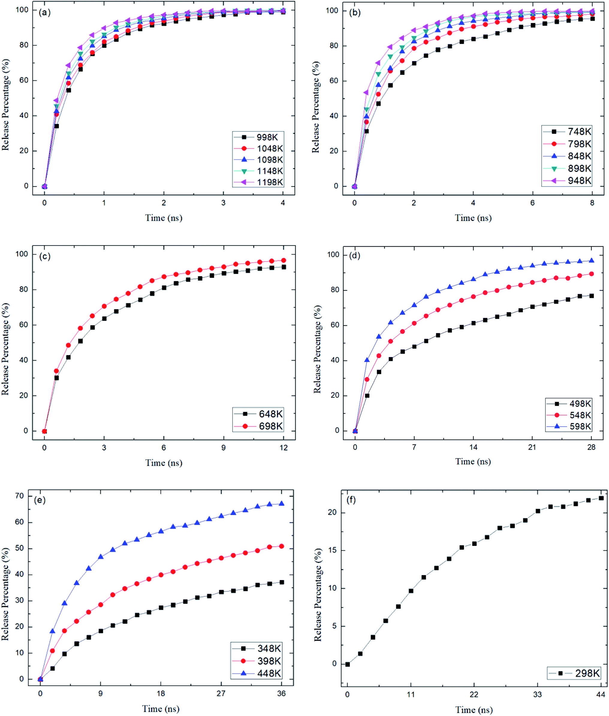
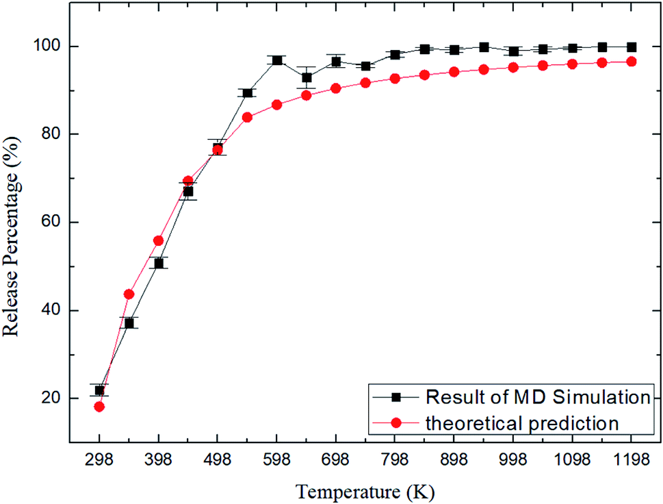
where N0 is the number of methane molecules released from the zeolite and N is the total number of methane molecules initially confined in the zeolite. It is noted that the release process is accompanied by the reabsorption of methane on zeolite pore surface and N0 is the net molecule number due to the two processes. Fig. 4 shows the release percentage as a function of time at different temperatures for all-silica MFI zeolite. It is seen that the time needed to release methane molecules depends on the temperature. The release process takes about 4 to 45 ns when the temperature T is varied from 298 to 1198 K. Fig. 5 depicts the final release percentage P0 as a function of temperature. It is clear that P0 increases with increasing T for T < 598 K. Beyond 598 K, P0 is roughly a constant, above 90%, indicating that most methane molecules are released from the zeolite. Further increase in temperature does not have significant effect on the methane release.
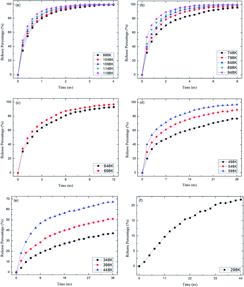 |
| | Fig. 4 Methane release percentage as a function of time at different temperatures. (a) 998 K to 1198 K, (b) 748 K to 948 K, (c) 648 K and 698 K, (d) 498 K to 598 K, (e) 348 K to 448 K, (f) 298 K. | |
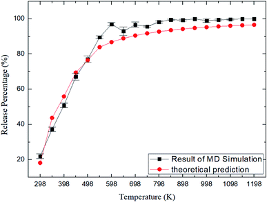 |
| | Fig. 5 Release percentage of methane as a function of temperature. Squares and circles are the results of MD simulations and theoretical predictions, respectively. | |
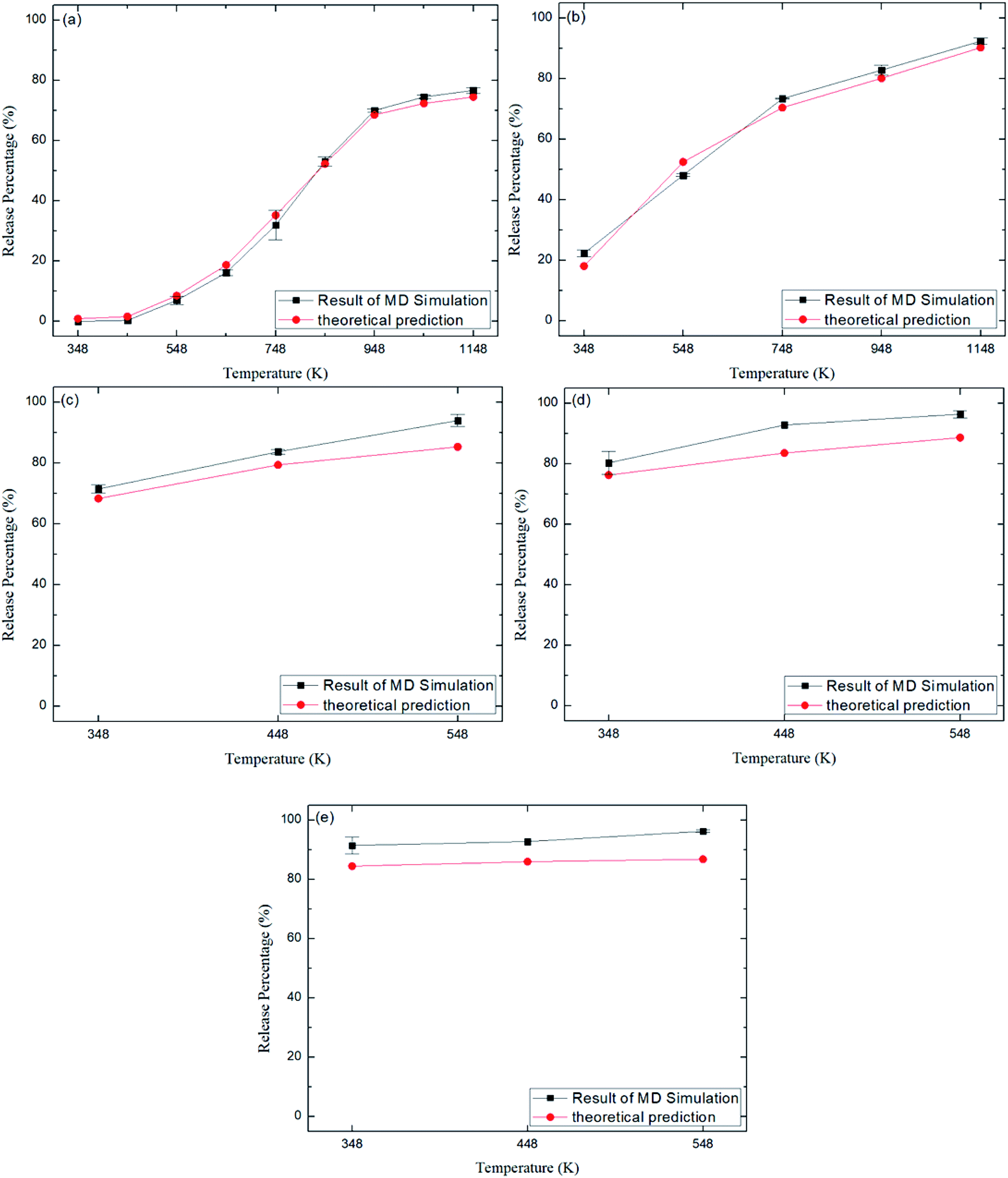
Fig. 6 depicts the final release percentages P0 for other zeolite structures at different temperatures. It is seen that at a given temperature, P0 generally increases with increasing pore size. For instance, at 348 K, the release percentage P0 ≈ 90% for CFI zeolite with average pore size of 7.3 Å (Table 2), as shown in Fig. 6e, while the release percentage is 0% for ABW zeolite due to the small pore size (∼3.5 Å) (Fig. 6a).
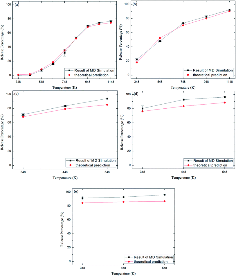 |
| | Fig. 6 Release percentage of methane in different zeolite structures in Table 2. (a) ABW. (b) TER. (c) VET. (d) OFF. (e) CFI. Squares and circles are the results of MD simulations and theoretical predictions, respectively. | |
The dynamics of molecules in a pore mainly depends on the kinetic energy E of the molecules and the potential distribution inside the pore.27,28 The former is determined by the temperature and the latter is governed by the structure of the pore and the molecular interactions. To be released from the zeolite, a methane molecule should have a sufficiently high kinetic energy to overcome potential energy barriers inside the pores. According to the Maxwell–Boltzmann velocity distribution, the kinetic energy distribution of the methane molecules follows
| |
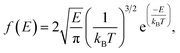 | (3) |
where
kB is the Boltzmann constant. If the maximum potential energy barrier in the zeolite nanochannels is denoted as Δ
G, the release percentage can be theoretically predicted by
| |
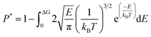 | (4) |
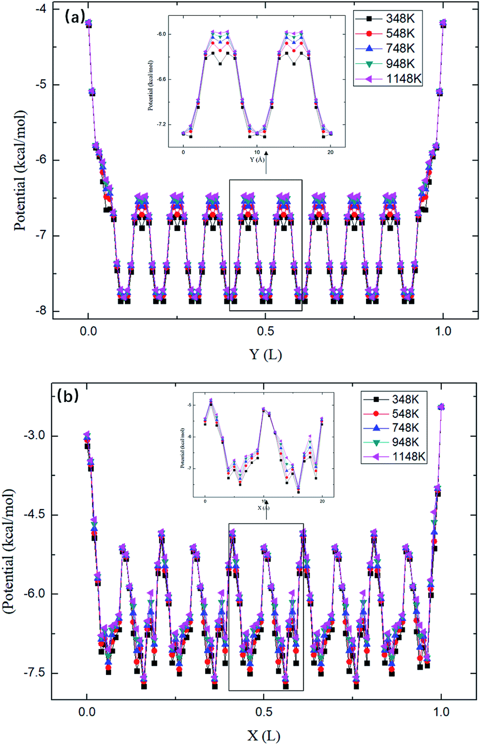
The maximum potential energy barrier ΔG depends on the molecular interactions and the pore size. Fig. 7 shows the average potential energy along the pore axis, Uavg(z), calculated through
| |
 | (5) |
where
β = 1/
kBT. It is seen that the energy barrier of zigzag channels is much higher than that in straight channels. Thus, for a molecule initially lying in a zigzag channel, it is very probable that it will migrate to the intersection of a straight channel and the zigzag channel and then is released from the zeolite through the straight channel, as illustrated in
Fig. 7.
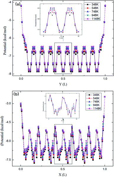 |
| | Fig. 7 The average potential profile of silicalite-1 structure. (a) Straight channel and (b) zigzag channel, where L is the length of the corresponding channel. | |
As shown in Fig. 7, the energy barriers, ΔG = 3.651, 3.527, 3.434, 3.208, 3.102 kcal mol−1 at 348, 548, 748, 948, and 1148 K, respectively. These energy barriers can be used to obtain the theoretical release percentages using eqn (4). The release percentage predicted by eqn (4) is also shown in Fig. 5. It is see that the theoretical predictions agree well with the MD results. Eqn (4) slightly underestimates the release percentage at high temperatures because it does not consider the fluctuation in kinetic energy and potential energy barrier.
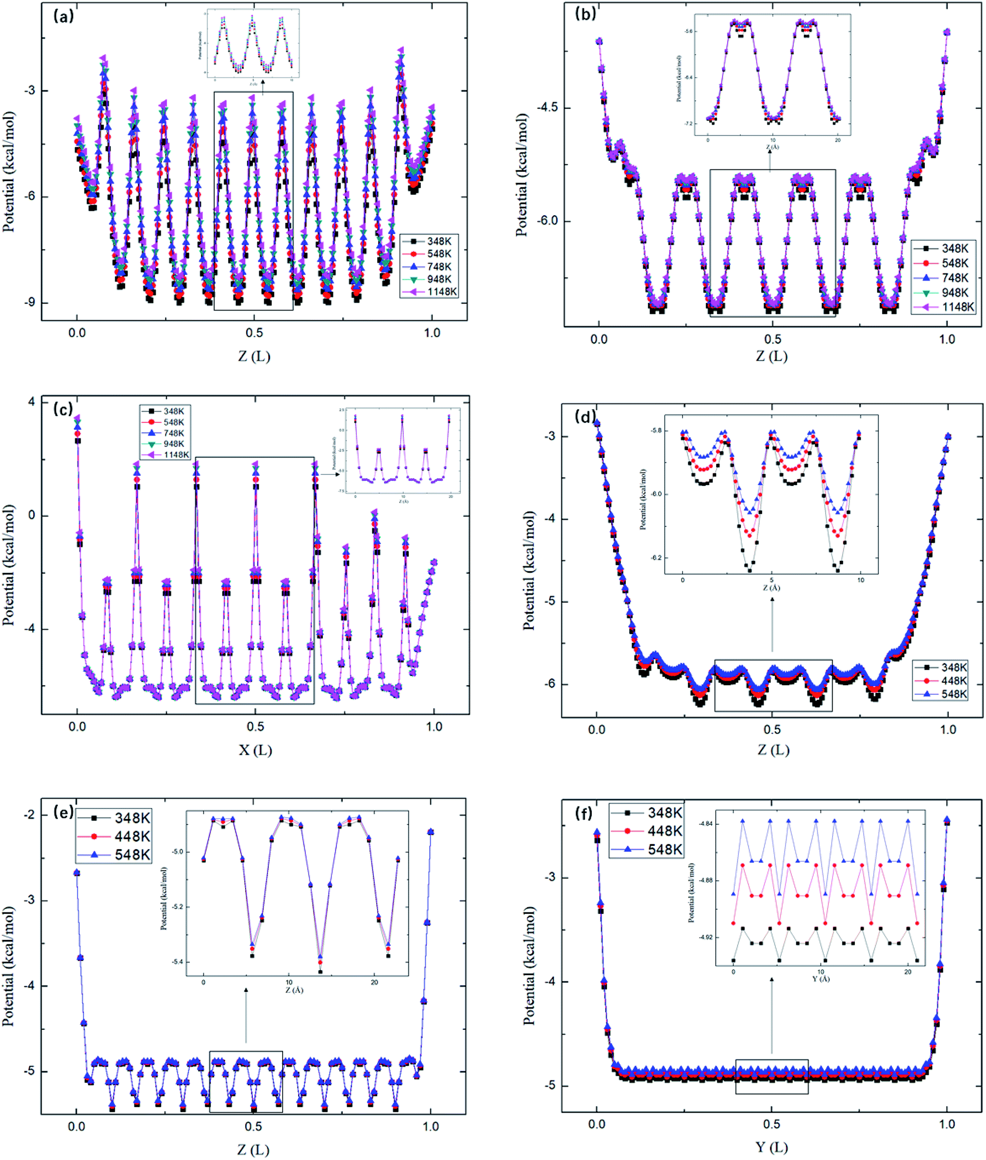
Fig. 8 depicts the energy barriers in the pores of other zeolite structures. It is seen that ΔG in ABW pores is the largest and that for CFI is the smallest, which are consistent with the release percentages shown in Fig. 6. Fig. 6 also shows the release percentages predicted by eqn (4). It is seen that eqn (4) works well for all the zeolite structures.
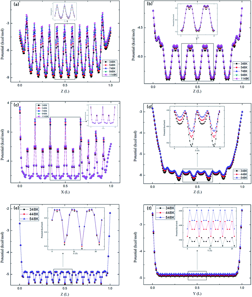 |
| | Fig. 8 The average potential profile of zeolite structures in Table 2. (a) ABW. (b) Straight channels of TER. (c) Zigzag channels of TER. (d) VET. (e) OFF. (f). CFI, where L is the length of the corresponding channel. | |
4. Conclusions
The effects of the temperature as well as pore size on the release of methane in zeolite nanochannels have been examined by MD simulations. The methane release percentage in MFI zeolite nanochannels increases with increasing temperature when T < 598 K. Above 598 K, most of the methane molecules are released from the zeolite and the release percentage remains roughly constant at a high value. Simulations for other zeolite structures show that methane molecules are apt to escape from nanoconfinements with large pore sizes, which have relatively low energy barriers. Theoretical predictions of the release percentages using the energy barriers obtained through MD simulations agree well with numerical results.
Conflicts of interest
There are no conflicts to declare.
Acknowledgements
This work was supported by the Research Grants Council of the Hong Kong Special Administrative Region under Grant No. 16210615, the National Natural Science Foundation of China (No. 51888103), and the Foundation for Innovative Research Groups of the National Natural Science Foundation of China (No. 51721004).
References
- J. Chen, F. Wang, H. Liu and H. Wu, Sci. China: Phys., Mech. Astron., 2016, 60, 014611 Search PubMed.
- J. D. Hughes, Nature, 2013, 494, 307–308 CrossRef CAS PubMed.
- T. A. Ho, L. J. Criscenti and Y. Wang, Sci. Rep., 2016, 6, 28053 CrossRef CAS PubMed.
- R. G. Loucks, R. M. Reed, S. C. Ruppel and D. M. Jarvie, J. Sediment. Res., 2009, 79, 848–861 CrossRef.
- S. L. Montgomery, D. M. Jarvie, K. A. Bowker and R. M. Pollastro, AAPG Bull., 2005, 89, 155–175 CrossRef.
- T. F. T. Rexer, M. J. Benham, A. C. Aplin and K. M. Thomas, Energy Fuels, 2013, 27, 3099–3109 CrossRef CAS.
- W. Zhou, Z. Zhang, H. Wang, Y. Yan and X. Liu, RSC Adv., 2018, 8, 33939–33946 RSC.
- G. P. Lithoxoos, A. Labropoulos, L. D. Peristeras, N. Kanellopoulos, J. Samios and I. G. Economou, J. Supercrit. Fluids, 2010, 55, 510–523 CrossRef CAS.
- X. Zhu and Y. P. Zhao, J. Phys. Chem. C, 2014, 118, 17737–17744 CrossRef CAS.
- N. Zucchetto and D. Brühwiler, RSC Adv., 2015, 5, 74638–74644 RSC.
- H. Wu, J. Chen and H. Liu, J. Phys. Chem. C, 2015, 119, 13652–13657 CrossRef CAS.
- W. Yu and K. Sepehrnoori, Fuel, 2014, 116, 455–464 CrossRef CAS.
- V. Shabro, C. Torres-Verdin and K. Sepehrnoori, SPE Annual Technical Conference and Exhibition, Society of Petroleum Engineers, San Antonio, Texas, USA, 2012 Search PubMed.
- Z. Li and H. Wang, Phys. Rev. Lett., 2005, 95, 014502 CrossRef PubMed.
- Z. Li and H. Wang, Phys. Rev. E: Stat., Nonlinear, Soft Matter Phys., 2003, 68, 061206 CrossRef PubMed.
- L. Li, J. Mo and Z. Li, Phys. Rev. Lett., 2015, 115, 134503 CrossRef PubMed.
- J. Mo, L. Li, J. Zhou, D. Xu, B. Huang and Z. Li, Phys. Rev. E: Stat., Nonlinear, Soft Matter Phys., 2015, 91, 033022 CrossRef PubMed.
- J. Mo, C. Li, L. Li, J. Wang and Z. Li, Phys. Fluids, 2016, 28, 082005 CrossRef.
- D. P. Broom and K. M. Thomas, MRS Bull., 2013, 05, 412–421 CrossRef.
- K. S. Smirnov and B. van de Graaf, J. Chem. Soc., Faraday Trans., 1996, 92, 2475–2480 RSC.
- J. Dong, X. Wang, H. Xu, Q. Zhao and J. Li, Int. J. Hydrogen Energy, 2007, 18, 4998–5004 CrossRef.
- C. Tedesco, L. Erra, M. Brunelli, V. Cipolletti, C. Gaeta, A. N. Fitch, J. L. Atwood and P. Neri, Chem.–Eur. J., 2010, 16, 2371–2374 CrossRef CAS PubMed.
- S. L. Mayo, B. D. Olafson and W. A. Goddard, J. Phys. Chem., 1990, 94, 8897–8909 CrossRef CAS.
- H. J. C. Berendsen, J. P. M. Postma, W. F. V. Gunsteren, A. Dinola and J. R. Haak, J. Chem. Phys., 1984, 81, 3684–3690 CrossRef CAS.
- U. Setzmann and W. Wagner, J. Phys. Chem. Ref. Data, 1991, 20, 1061–1155 CrossRef CAS.
- C. Baerlocher, W. M. Meier and D. H. Olson, Atlas of Zeolite Framework Types, Elsevier, 2007, pp. 174–175 Search PubMed.
- R. L. June, A. T. Bell and D. N. Theodorou, J. Phys. Chem., 1990, 94, 8232–8240 CrossRef CAS.
- Q. Yang and C. Zhong, J. Phys. Chem. B, 2006, 110, 17776–17783 CrossRef CAS PubMed.
|
| This journal is © The Royal Society of Chemistry 2019 |
Click here to see how this site uses Cookies. View our privacy policy here. 
 Open Access Article
 This Open Access Article is licensed under a Creative Commons Attribution-Non Commercial 3.0 Unported Licence
 a,
Zhigang Li
a,
Zhigang Li