 Open Access Article
Comparison of electrochemical performance of LiNi1−xCoxO2 cathode materials synthesized from coated (1−x)Ni(OH)2@xCo(OH)2 and doped Ni1−xCox(OH)2 precursors†
Lei Tang a,
Gang Lib,
Peng Xiaoa,
Xu Chen
 a and
Wensheng Yang
 *a
*a
aState Key Laboratory of Chemical Resource Engineering, Beijing University of Chemical Technology, Beijing 100029, China. E-mail: yangws@mail.buct.edu.cn
bSinopec Research Institute of Petroleum Processing, Beijing 100083, China
First published on 19th March 2019
Abstract
LiNi1−xCoxO2 cathode materials were successfully synthesized from coated (1−x)Ni(OH)2@xCo(OH)2 and doped Ni1−xCox(OH)2 precursors, and the effects of the Co site and content in the precursor and final cathode material on the structure, morphology, and electrochemical performance of the cathodes were investigated using X-ray diffraction, scanning electron microscopy, and charge–discharge tests. The electrochemical performance of the materials prepared from the coated precursor was generally better than that of the materials prepared from the doped precursor. However, with increasing Co content, the performance difference gradually decreased. Among the as-prepared samples, the sample coated with 12 mol% Co delivered an excellent reversible capacity of 213.8 mA h g−1 at 0.1C and the highest capacity retention of 88.5% after 100 cycles at 0.2C in the voltage range of 2.75–4.3 V. High-performance LiNi1−xCoxO2 materials were successfully synthesized, and our findings clearly reveal the differences in the electrochemical properties of the materials prepared from the two different precursors with increasing Co content, thereby providing a valuable reference for the synthesis of high-performance Ni-rich layered cathode materials for Li-ion batteries.
1. Introduction
Li-ion batteries (LIBs) have been widely used for various applications ranging from portable electronic devices to electric vehicles (EVs) because of their excellent power and energy densities.1–3 Recently, there has been increased demand for longer standby times for smartphones and longer driving ranges for EVs, both of which require LIBs with higher energy densities.4–6 To resolve these issues, Ni-rich binary and ternary layered LiNi1−xMxO2 (1−x > 0.6) materials have been developed by doping other metals M (M = one or two metals among Co, Mn, Mg, Al, Ti, Zr, etc.) into the host structure of LiNiO2 because of their high reversible capacity (>190 mA h g−1).7–9 The synthesis of Ni-rich layered materials is much less difficult than that of LiNiO2. In addition, the structural stability upon cycling can also be improved,10 which is mainly attributed to the reduction of Ni2+ ion migration from the transition-metal slab to the Li slab during charge–discharge processes via stabilization of the valence of the Ni ions or the generation of electrostatic repulsion.To further improve the electrochemical performance of Ni-rich layered materials, precursors using different doping element sites have been designed, and the effects on the final products have been investigated. For example, Ni-rich layered LiNi1−x−yCoxMnyO2 materials with novel structures, such as core–shell,11–13 concentration-gradient,14–16 and full concentration-gradient17–19 structures, have been designed and synthesized by different research groups. Through structure design, the electrochemical performance and safety have been further enhanced. However, it remains controversial whether the core–shell and concentration-gradient structures of the precursors can be maintained in the final products. Some researchers have reported that the diffusion of the cations between the core and shell phases occurs during sintering, which makes a priori design of a particular core–shell structure difficult.20–24 However, Li–Ni–Co–Mn–O2 materials synthesized from precursors with core–shell, concentration-gradient, or full concentration-gradient structures still exhibit improved electrochemical performance. In our recent work,25 three types of LiNi0.88Co0.12O2 materials were synthesized from three different structured precursors, namely completely coated 0.88Ni(OH)2@0.12Co(OH)2, semi-coated and semi-doped 0.94Ni0.936Co0.064(OH)2@0.06Co(OH)2, and completely doped Ni0.88Co0.12(OH)2. Although the core–shell structures of the completely coated and semi-coated/semi-doped precursors disappeared after sintering with LiOH·H2O and the three products maintained the same structures, the product synthesized from the completely coated 0.88Ni(OH)2@0.12Co(OH)2 precursor still exhibited the best electrochemical performance.
Therefore, it is of interest to determine the changing regularity of precursor structures during the sintering reaction process and its effect on the electrochemical performance of the final materials. In this work, a series of experiments were conducted to investigate the effects of the Co site and content on the electrochemical performance of two types of LiNi1−xCoxO2 materials derived from coated (1−x)Ni(OH)2@xCo(OH)2 and doped Ni1−xCox(OH)2 precursors (x = 0.04, 0.08, 0.12, 0.16). In addition, the changing trends of the difference as a function of the Co content were also investigated. The Co site and content in the precursor were observed to affect the electrochemical properties of the material, with the material synthesized from the coated precursor exhibiting improved electrochemical properties and the difference between the electrochemical properties of the two materials decreasing with increasing Co content.
2. Experimental
2.1. Material synthesis
![[thin space (1/6-em)]](https://www.rsc.org/images/entities/char_2009.gif) :
:![[thin space (1/6-em)]](https://www.rsc.org/images/entities/char_2009.gif) Co = (1−x)
Co = (1−x)![[thin space (1/6-em)]](https://www.rsc.org/images/entities/char_2009.gif) :
:![[thin space (1/6-em)]](https://www.rsc.org/images/entities/char_2009.gif) x mole ratio] with a concentration of 2.0 M was pumped into a CSTR (capacity = 50 L). At the same time, a 6.0 M NaOH solution and a desired amount of NH4OH solution as the chelating agent were separately fed into the reactor. The concentration of the solution, pH, temperature, and stirring speed of the mixture in the reactor were carefully controlled. The precursors were filtered and washed with deionized water several times and then dried at 120 °C for 15 h.
x mole ratio] with a concentration of 2.0 M was pumped into a CSTR (capacity = 50 L). At the same time, a 6.0 M NaOH solution and a desired amount of NH4OH solution as the chelating agent were separately fed into the reactor. The concentration of the solution, pH, temperature, and stirring speed of the mixture in the reactor were carefully controlled. The precursors were filtered and washed with deionized water several times and then dried at 120 °C for 15 h.![[thin space (1/6-em)]](https://www.rsc.org/images/entities/char_2009.gif) :
:![[thin space (1/6-em)]](https://www.rsc.org/images/entities/char_2009.gif) (Ni + Co) = 1.05
(Ni + Co) = 1.05![[thin space (1/6-em)]](https://www.rsc.org/images/entities/char_2009.gif) :
:![[thin space (1/6-em)]](https://www.rsc.org/images/entities/char_2009.gif) 1 mole ratio] and thoroughly ball-milled for 3 h. The mixtures were preheated at 580 °C for 5 h, and the calcined materials were then ball-milled for 1 h to obtain the intermediate products. For x = 0.04–0.12, the second stage of the synthesis was performed at 680 °C for 20 h in a flowing O2 atmosphere of 1 L min−1. For x = 0.16, the synthesis temperature was 720 °C. Then, the final LiNi1−xCoxO2 materials derived from the different structured precursors were obtained.
1 mole ratio] and thoroughly ball-milled for 3 h. The mixtures were preheated at 580 °C for 5 h, and the calcined materials were then ball-milled for 1 h to obtain the intermediate products. For x = 0.04–0.12, the second stage of the synthesis was performed at 680 °C for 20 h in a flowing O2 atmosphere of 1 L min−1. For x = 0.16, the synthesis temperature was 720 °C. Then, the final LiNi1−xCoxO2 materials derived from the different structured precursors were obtained.2.2. Material characterization
The compositions of the as-prepared precursors and lithium oxides were determined using inductively coupled plasma atomic emission spectrometry (ICP-AES; SPS-7800, Japan). The particle morphologies of the as-prepared precursors and lithium oxides were examined using scanning electron microscopy (SEM; Supra 55, ZEISS, Germany). Powder X-ray diffraction (XRD, Ultima III, Rigaku, Japan) measurements using Cu Kα radiation (λ = 0.154 nm) were employed to identify the crystalline phases of the synthesized materials. XRD data were obtained in the 2θ range of 10–80° at a scan rate of 5° min−1. The lattice parameters were calculated from the XRD data using the least-squares method.2.3. Electrochemical measurements
The electrochemical performance of each synthesized powder was assessed using a 2032 coin-type cell. The cell consisted of a cathode and a lithium metal anode separated by a porous polypropylene film. The cathode was fabricated using a mixture of the prepared powder (80 wt%), carbon black (10 wt%), and polyvinylidene fluoride (10 wt%) in N-methyl-2-pyrrolidinone. The slurry was spread onto Al foil and dried in a vacuum oven at 110 °C. The electrolyte used was 1 M LiPF6 in EC–DMC–DEC (1![[thin space (1/6-em)]](https://www.rsc.org/images/entities/char_2009.gif) :
:![[thin space (1/6-em)]](https://www.rsc.org/images/entities/char_2009.gif) 1
1![[thin space (1/6-em)]](https://www.rsc.org/images/entities/char_2009.gif) :
:![[thin space (1/6-em)]](https://www.rsc.org/images/entities/char_2009.gif) 1 volume ratio). The cells were charged and discharged by applying a constant current density of 20 mA g−1 (0.1C) for the initial 4 cycles and then cycled at 40 mA g−1 (0.2C) for the subsequent 96 cycles in the voltage range of 2.75–4.3 V at room temperature on a LAND CT-2001A test system (Wuhan).
1 volume ratio). The cells were charged and discharged by applying a constant current density of 20 mA g−1 (0.1C) for the initial 4 cycles and then cycled at 40 mA g−1 (0.2C) for the subsequent 96 cycles in the voltage range of 2.75–4.3 V at room temperature on a LAND CT-2001A test system (Wuhan).
3. Results and discussion
3.1. Chemical composition
ICP-AES analysis was performed on the two different structural precursors as well as on the final products synthesized from these precursors, and the results are presented in Table 1. Although the synthesis processes of the materials differed, the Ni and Co contents in the precursors and final products were basically the same as the feed ratios.| Ni/Co feed ratio | Composition of precursor | Composition of final product | ||
|---|---|---|---|---|
| Coated precursor | Doped precursor | From coated precursor | From doped precursor | |
| 96/4 | 0.959Ni(OH)2@0.041Co(OH)2 | Ni0.958Co0.042(OH)2 | Li1.036Ni0.959Co0.041O2 | Li1.039Ni0.958Co0.042O2 |
| 92/8 | 0.919Ni(OH)2@0.081Co(OH)2 | Ni0.919Co0.081(OH)2 | Li1.036Ni0.919Co0.081O2 | Li1.038Ni0.919Co0.081O2 |
| 88/12 | 0.877Ni(OH)2@0.123Co(OH)2 | Ni0.876Co0.124(OH)2 | Li1.038Ni0.877Co0.123O2 | Li1.037Ni0.876Co0.124O2 |
| 84/16 | 0.834Ni(OH)2@0.166Co(OH)2 | Ni0.843Co0.157(OH)2 | Li1.037Ni0.834Co0.166O2 | Li1.035Ni0.843Co0.157O2 |
3.2. SEM characterization
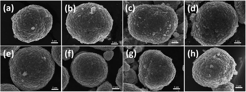
Because of the different synthesis processes used to prepare the precursors, their morphologies differed. SEM images of the coated (1−x)Ni(OH)2@xCo(OH)2 precursors are presented in Fig. 1(a–d). The same Ni(OH)2 powders were used to synthesize four coated precursors with different Co contents. The particle morphology of Ni(OH)2 was spherical, and the average particle diameter was approximately 10 μm. In our previous work,25 atomic emission spectroscopy (AES) was used to determine the radial concentration distribution of Ni and Co in a 0.88Ni(OH)2@0.12Co(OH)2 precursor, revealing that the surface of Ni(OH)2 was coated with a Co(OH)2 layer, forming a core–shell structure. Furthermore, as clearly observed in Fig. 1(a–c), the smoothness of the surface of the material decreased with increasing Co content, and almost no Co(OH)2 particles were observed in the single phase. This finding indicates that when the Co(OH)2 coating amount was relatively low (x ≤ 0.12), most of the Co(OH)2 material was coated on the surface of the Ni(OH)2 particles. However, when the coating amount x was increased to 0.16, as shown in Fig. 1(d), some Co(OH)2 particles with small particle size were not coated on the surface of Ni(OH)2 particles and instead existed in a single phase. This result indicates that the amount of the coating layer is limited and that the coating amount cannot be increased without restriction. As observed in Fig. 1(e–h), unlike the coated precursors, there was little difference in the morphologies of the four doped Ni1−xCox(OH)2 precursors with varying x in the range of 0.04–0.16. The morphologies of all four doped precursors were spherical or spherical-like with an average particle size of approximately 10 μm. This result was expected because Ni(OH)2 and Co(OH)2 possess similar structures and can be composited in any proportion.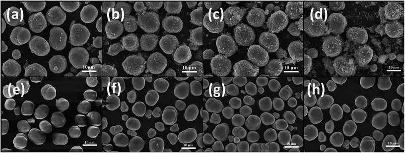 | ||
| Fig. 1 SEM images of coated (1−x)Ni(OH)2@xCo(OH)2 precursors, x = (a) 0.04, (b) 0.08, (c) 0.12, and (d) 0.16, and doped Ni1−xCox(OH)2 precursors, x = (e) 0.04, (f) 0.08, (g) 0.12, and (h) 0.16. | ||
Fig. 2 presents SEM images of the final LiNi1−xCoxO2 oxides. The spherical morphologies of the precursors were maintained even after high-temperature calcination. Additionally, no obvious differences were observed among the morphologies of the final LiNi1−xCoxO2 materials (x = 0.04, 0.08, 0.12, 0.16) regardless of whether the precursor had a coated or doped structure. For the LiNi1−xCoxO2 materials synthesized from the coated precursors, Ni and Co metal ions diffused into each other, and the core–shell structure disappeared during the high-temperature calcination,24,25 resulting in the same structure and radial elemental distribution as those of the lithium oxides synthesized from the doped precursors.
3.3. Crystal structure
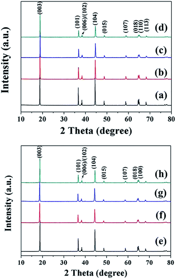
The LiNi1−xCoxO2 materials were synthesized by lithiating the different structured hydroxide precursors with LiOH·H2O using a two-step high-temperature heat-treatment process. The intermediate products after the first stage of calcination and the final products were characterized using XRD. XRD patterns of the intermediate products derived from the coated precursors are presented in Fig. 3. The clear (003) and (104) reflection peaks corresponding to LiNiO2 oxides after calcination at 580 °C for 5 h indicate the basic α-NaFeO2 layered structure of the intermediate products. However, splitting of the (006)/(012) and (018)/(110) peaks did not occur, indicating that a well-ordered layered structure was not completely developed. Additionally, for x = 0.04 and 0.08, no peaks corresponding to the Li1−xCoO2 phase appeared in the XRD patterns (Fig. 3(a) and (b)). This finding may be attributed to the small amount and weak peak intensity of Li1−xCoO2 materials; for x ≥ 0.12, impurity peaks corresponding to the Li1−xCoO2 phase appeared in the XRD patterns (Fig. 3(c–d)). The above results indicate that at 580 °C, the interdiffusion degree between Ni and Co metal ions was very small and the intermediate products were core–shell-structured (1−x)LiNiO2@xLiCoO2 materials. The XRD patterns of the four intermediate products derived from the doped Ni1−xCox(OH)2 precursors were similar (Fig. 4): (003) and (104) peaks appeared, and splitting of the (006)/(012) and (018)/(110) peaks was not observed. No impurity peaks appeared in the XRD patterns, indicating that the intermediate product obtained from the doped precursor after the first stage of calcination did not contain the Li1−xCoO2 phase with increasing Co content.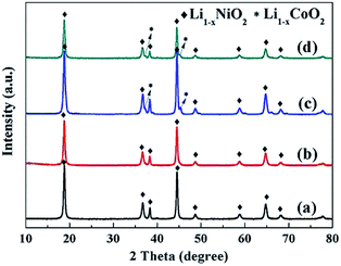 | ||
| Fig. 3 XRD patterns of intermediate LiNi1−xCoxO2 products synthesized from coated precursors after being calcined at 580 °C for 5 h: x = (a) 0.04, (b) 0.08, (c) 0.12, and (d) 0.16. | ||
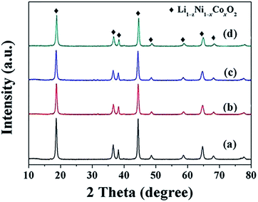 | ||
| Fig. 4 XRD patterns of intermediate LiNi1−xCoxO2 products synthesized from doped precursors after being calcined at 580 °C for 5 h: x = (a) 0.04, (b) 0.08, (c) 0.12, and (d) 0.16. | ||
Fig. 5 presents the XRD patterns of the final LiNi1−xCoxO2 (x = 0.04, 0.08, 0.12, 0.16) products synthesized from the coated (1−x)Ni(OH)2@xCo(OH)2 and doped Ni1−xCox(OH)2 precursors. All the diffraction peaks can be indexed to hexagonal LiNiO2 with a well-ordered layered structure (JCPDS no. 09-0063), indicating the high phase purity. Unlike the intermediate products for the coated precursors, the peaks corresponding to the Li1−xCoO2 coating in the final product completely disappeared because the Ni and Co metal ions completely diffused into each other, forming a homogeneous structure.
The structural parameters of the as-prepared samples were calculated using the least-squares method, and the results are summarized in Table 2. With increasing Co content x from 0.04 to 0.16, the lattice parameters c and a and cell volume decreased because the smaller-sized Co3+ replaced Ni2+, resulting in crystal volume shrinkage. The c/a ratios of the final products were both larger than 4.9, further confirming the highly layered structure and lower cation mixing for both samples.26 In addition, the intensity ratio I(003)/I(104) increased upon increasing x from 0.04 to 0.12 for the two types of final LiNi1−xCoxO2 products, indicating that higher Co content led to a lower degree of Li+/Ni2+ cation mixing and a better layered structure. In addition, the I(003)/I(104) intensity ratios of the LiNi1−xCoxO2 products synthesized from the coated precursor were higher than those of the products synthesized from the doped precursor for the same Co content x. The coating of Co(OH)2 on the surface of spherical Ni(OH)2 particles can have a “barrier effect”, decreasing the rate of Li diffusing into the core NiO material and leaving sufficient time for the oxidation of Ni2+ ions to Ni3+ ions as much as possible, thus resulting in a decrease of the Li+/Ni2+ cation mixing and leading to a better layered structure.25 However, the I(003)/I(104) intensity ratio of the LiNi0.84Co0.16O2 material synthesized from the coated 0.84Ni(OH)2@0.16Co(OH)2 precursor was smaller than that of the LiNi0.84Co0.16O2 material synthesized from the doped Ni0.84Co0.16(OH)2 precursor and even smaller than that of the LiNi0.88Co0.12O2 synthesized from the coated 0.88Ni(OH)2@0.12Co(OH)2 precursor. Most likely, some Co(OH)2 particles precipitated in a single phase during the synthesis of the 0.84Ni(OH)2@0.16Co(OH)2 coated precursor, resulting in a composite of LiNi1−xCoxO2 (x < 0.16) and a very small amount of LiCoO2 as the final product. The optimal temperature (720 °C) of Ni-rich material is not suitable for the formation of LiCoO2; therefore, the layered structure of the final LiNi0.84Co0.16O2 material was inferior to that of the LiNi0.88Co0.12O2 material.
| Items | From coated (1−x)Ni(OH)2@xCo(OH)2 | From doped Ni1−xCox(OH)2 | ||||||
|---|---|---|---|---|---|---|---|---|
| x = 0.04 | x = 0.08 | x = 0.12 | x = 0.16 | x = 0.04 | x = 0.08 | x = 0.12 | x = 0.16 | |
| c (Å) | 14.218 | 14.194 | 14.153 | 14.127 | 14.226 | 14.210 | 14.145 | 14.140 |
| a (Å) | 2.881 | 2.875 | 2.865 | 2.855 | 2.885 | 2.880 | 2.861 | 2.856 |
| c/a | 4.935 | 4.937 | 4.940 | 4.948 | 4.931 | 4.934 | 4.944 | 4.951 |
| Volume (Å3) | 102.20 | 101.60 | 100.60 | 99.72 | 102.54 | 102.07 | 100.27 | 99.88 |
| I(003)/I(104) | 1.504 | 1.682 | 1.865 | 1.803 | 1.435 | 1.437 | 1.503 | 1.870 |
3.4. Electrochemical performance
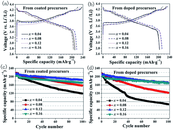
We investigated the differences in the electrochemical performance of LiNi1−xCoxO2 materials derived from the different structured precursors as a function of the Co content x. Coin-type cells using LiNi1−xCoxO2 as the positive electrode and Li metal as the negative electrode were used for the electrochemical measurements. The cells were charged and discharged at a constant current density of 20 mA g−1 for the initial four cycles and 40 mA g−1 for the subsequent 96 cycles. The initial charge–discharge curves and the cycling performance are shown in Fig. 6. As observed in Fig. 6(a), the LiNi1−xCoxO2 materials derived from the coated precursors exhibited discharge specific capacities of 210.2, 217.5, 213.8, and 205.3 mA h g−1 for x = 0.04, 0.08, 0.12, and 0.16, respectively. These results indicate that the highest discharge specific capacity was obtained for the LiNi0.92Co0.08O2 material and not LiNi0.96Co0.04O2 with the highest Ni content. As observed in Fig. 6(b), the LiNi1−xCoxO2 materials derived from the doped precursors exhibited discharge specific capacities of 203.3, 212.8, 210.2, and 202.7 mA h g−1 for x = 0.04, 0.08, 0.12, and 0.16, respectively. The highest discharge specific capacity was also obtained for the LiNi0.92Co0.08O2 material. The Li/LiNi0.96Co0.04O2 cells prepared using the two different structured precursors exhibited initial coulombic efficiencies of approximately 88%, whereas the Li/LiNi1−xCoxO2 (x = 0.08, 0.12, 0.16) cells prepared from the two different structured precursors exhibited similar initial coulombic efficiencies of approximately 91–93% at 0.1C. Therefore, it is reasonable to conclude that the LiNi0.96Co0.04O2 materials with such high Ni content had a poor layered structure, which resulted in a high irreversible capacity and lower initial discharge capacity. The 100th capacity retention ratios of the LiNi1−xCoxO2 materials synthesized from the coated precursors (Fig. 6(c)) were 60.7%, 75.4%, 88.5%, and 86.6% for x = 0.04, 0.08, 0.12, and 0.16, respectively. The best cycling performance was achieved for the LiNi0.88Co0.12O2 material. In comparison, for the LiNi1−xCoxO2 materials synthesized from the doped precursors (Fig. 6(d)), the capacity retention ratios after 100 cycles were 36.0%, 60.6%, 82.6%, and 87.1%, respectively, and the cycling performance increased with increasing Co content, similar to results previously reported in the literature.20 The rate performances of the materials at different current rates indicate that the LiNi0.88Co0.12O2 material prepared from the coated precursor exhibited the optimal performance, as shown in Fig. S1.†To further compare the different effects of Co in the LiNi1−xCoxO2 products prepared from the coated and doped precursors with the same Co content, the results of the initial discharge specific capacity and 100-cycle capacity retention ratios as a function of the Co content x are summarized in Fig. 7. ΔCa is the difference in the initial discharge specific capacity of the LiNi1−xCoxO2 products prepared from the two different structural precursors, and ΔRet is the difference in the capacity retention after 100 cycles. With increasing Co content x, the specific capacity and 100-cycle capacity retention ratio of the two types of materials showed the same tendencies. Moreover, the initial discharge specific capacities of the products prepared from the coated precursors were still higher than those prepared from the doped precursors with the same Co content x, as observed in Fig. 7(a); however, ΔCa decreased with increasing Co content x. The capacity retention ratios of the two types of materials were similar, as observed in Fig. 7(b), except that the LiNi1−xCoxO2 product derived from the doped precursor exhibited a slightly higher capacity retention ratio at a Co content of x = 0.16. The electrochemical performance of the LiNi1−xCoxO2 product prepared from the coated precursor was generally superior to that of the product prepared from the doped precursor. This finding can be attributed to the “barrier effect” of the coated Co(OH)2 layer, which left sufficient time for the oxidation of Ni2+ ions to Ni3+ as much as possible and thus decreased the Li+/Ni2+ cation mixing and led to the high electrochemical performance. The cycling performance of the LiNi0.84Co0.16O2 synthesized from the doped precursor exceeded that of the material synthesized from the coated precursor because of the high coating content: some Co(OH)2 materials could not be coated on the surface of the Ni(OH)2 particles and formed in a single phase; thus, they did not have a coating effect. The Co(OH)2 existing in the single phase could not be transformed into LiCoO2 materials with good electrochemical performance under synthesis conditions suitable for Ni-rich materials.
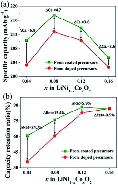 | ||
| Fig. 7 Initial discharge specific capacity and 100th capacity retention of LiNi1−xCoxO2 materials synthesized from different structured precursors as a function of Co content x. | ||
In summary, the products prepared from the coated precursors were generally superior to the products prepared from the doped precursors for the preparation of LiNi1−xCoxO2 materials, especially at lower Co contents. However, because there is an upper limit to the effective coating layer amount, for high coating amounts, such as Co content x = 0.16, the difference in the electrochemical properties of the products prepared from the coated and doped precursors was reduced. The electrochemical properties of the products prepared from the coated precursor were sometimes even worse than those of the products prepared from the doped precursor at higher Co content.
4. Conclusions
LiNi1−xCoxO2 materials were successfully synthesized from coated (1−x)Ni(OH)2@xCo(OH)2 and doped Ni1−xCox(OH)2 precursors. The differences in the electrochemical performances of the LiNi1−xCoxO2 materials derived from the different structured precursors and the changing trends of the difference as a function of the Co content x were investigated. For x ≤ 0.12, the LiNi1−xCoxO2 materials synthesized from the coated precursors exhibited more stable structures and better electrochemical performance. The LiNi0.88Co0.12O2 material prepared from the coated precursor exhibited a high discharge specific capacity of 213.8 mA h g−1 at 0.1C and good cycling performance with a capacity retention of 88.5% after 100 cycles at 0.2C. In contrast, for x > 0.12, the LiNi1−xCoxO2 materials synthesized from the doped precursor were preferred because some Co(OH)2 could not be coated on the surface of the core materials, resulting in poorer electrochemical performance of the final LiNi1−xCoxO2 products.Conflicts of interest
There are no conflicts to declare.Acknowledgements
This work was funded by the National Natural Science Foundation of China (U1407118 and 21521005), and Research Institute of Petroleum Processing Sinopec (218025-1).References
- F. Schipper, M. Dixit, D. Kovacheva, M. Talianker, O. Haik, J. Grinblat, E. M. Erickson, C. Ghanty, D. T. Major, B. Markovsky and D. Aurbach, J. Mater. Chem. A, 2016, 4, 16073–16084 RSC.
- H. Xie, K. Du, G. Hu, Z. Peng and Y. Cao, J. Phys. Chem. C, 2016, 120, 3235–3241 CrossRef CAS.
- B. Huang, X. Li, Z. Wang, H. Guo, L. Shen and J. Wang, J. Power Sources, 2014, 252, 200–207 CrossRef CAS.
- M. Ko, S. Chae, J. Ma, N. Kim, H. W. Lee, Y. Cui and J. Cho, Nat. Energy, 2016, 1, 16113 CrossRef CAS.
- P. Zhou, H. Meng, Z. Zhang, C. C. Chen, Y. Lu, J. Cao, F. Cheng and J. Chen, J. Mater. Chem. A, 2017, 5, 12361 RSC.
- Y. Zhang, M. Nie and Z. Wang, RSC Adv., 2016, 6, 65941 RSC.
- S. U. Woo, B. C. Park, C. S. Yoon, S. T. Myung, J. Prakash and Y. K. Sun, J. Electrochem. Soc., 2007, 154, A649 CrossRef CAS.
- P. Oh, S.-M. Oh, W. Li, S. Myeong, J. Cho and A. Manthiram, Adv. Sci., 2016, 3, 11 Search PubMed.
- Z. Zhang, D. Chen and C. Chang, RSC Adv., 2017, 7, 51721 RSC.
- G. Wang, L. Yi and X. Wang, RSC Adv., 2016, 6, 46325 RSC.
- Y. K. Sun, S. Myung, A. Byungchun Park and K. Amine, Chem. Mater., 2006, 18, 5159–5163 CrossRef CAS.
- Y. K. Sun, S. Myung, K. I. M. Myung-Hoon and K. I. M. Jung-Hyun, Electrochem. Solid-State Lett., 2006, 9, A171–A174 CrossRef CAS.
- Y. K. Sun, S. T. Myung, M. H. Kim, J. Prakash and K. Amine, J. Am. Chem. Soc., 2005, 127, 13411–13418 CrossRef CAS PubMed.
- Y. K. Sun, B.-R. Lee, H.-J. Noh, H. Wu, S.-T. Myung and K. Amine, J. Mater. Chem., 2011, 21, 10108 RSC.
- Y. K. Sun, D.-H. Kim, C. S. Yoon, S.-T. Myung, J. Prakash and K. Amine, Adv. Funct. Mater., 2010, 20, 485–491 CrossRef CAS.
- J. Wang, C. Du, C. Yan, X. Xu and Y. Gao, RSC Adv., 2016, 6, 26307 RSC.
- Y. K. Sun, Z. Chen, H. J. Noh, D. J. Lee, H. G. Jung, Y. Ren, S. Wang, S. Y. Chong, S. T. Myung and K. Amine, Nat. Mater., 2012, 11, 942–947 CrossRef CAS PubMed.
- U. H. Kim, E.-J. Lee, C. S. Yoon, S.-T. Myung and Y.-K. Sun, Adv. Energy Mater., 2016, 6, 1601417 CrossRef.
- Z. Sun, D. Wang, Y. Fan and L. Niu, RSC Adv., 2016, 6, 103747 RSC.
- J. Li, R. Doig, H. Liu, G. Botton and J. R. Dahn, J. Electrochem. Soc., 2016, 163, A2841–A2848 CrossRef CAS.
- X. Yang, X. Wang, L. Hu, G. Zou, S. Su, Y. Bai, H. Shu, Q. Wei, B. Hu, L. Ge, D. Wang and L. Liu, J. Power Sources, 2013, 242, 589–596 CrossRef CAS.
- J. Li, R. Shunmugasundaram, R. Doig and J. R. Dahn, Chem. Mater., 2016, 28, 162–171 CrossRef CAS.
- Y. Zhang, H. Shi, D. Song, H. Zhang, X. Shi and L. Zhang, J. Power Sources, 2016, 327, 38–43 CrossRef CAS.
- J. Li, R. Doig, J. Camardese, K. Plucknett and J. R. Dahn, Chem. Mater., 2015, 27, 7765–7773 CrossRef CAS.
- G. Li, L. Qi, P. Xiao, Y. Yu, X. Chen and W. Yang, Electrochim. Acta, 2018, 270, 319–329 CrossRef CAS.
- L. Zhang, J. Wang and X. Yang, ACS Appl. Mater. Interfaces, 2018, 10, 11663–11670 CrossRef CAS PubMed.
Footnote |
| † Electronic supplementary information (ESI) available. See DOI: 10.1039/c8ra10116g |
| This journal is © The Royal Society of Chemistry 2019 |

