
 Open Access Article
 This Open Access Article is licensed under a Creative Commons Attribution-Non Commercial 3.0 Unported Licence
Computer simulation study on the self-assembly of tethered nanoparticles with tunable shapes†
Sheng-Fang Lu,
Bing-Yu Li,
Yan-Chun Li * and
Zhong-Yuan Lu
* and
Zhong-Yuan Lu
State Key Laboratory of Supramolecular Structure and Materials, Laboratory of Theoretical and Computational Chemistry, Institute of Theoretical Chemistry, Jilin University, Changchun 130023, China. E-mail: liyanchun@jlu.edu.cn
First published on 11th January 2019
Abstract
We built a tethered nanoparticle (TNP) model that is composed of a nanoparticle with a hydrophobic tethered polymer chain. The shape of the nanoparticle can be tuned from a pure rigid cube to a soft sphere, mimicking the increase of grafting density on the nanocube surfaces. With this model, we study the self-assembly of TNPs in dilute solution using a dissipative particle dynamics simulation technique, and especially focus on the influence of particle shape, tethered chain length, and grafting density on the self-assembly structures. Some intriguing aggregates such as spherical micelles, pearl-necklace-like structures, cubic columnar structures, handshake structures, core–shell–corona micelles, and four-patch micelles have been observed when varying the interactions between cubes and solvents and the lengths of tethered chain. Modifying the nanocube surface with some hydrophilic grafted chains helps the TNPs form small micelles. Increased steric repulsion due to chain overlapping at larger grafting densities results in shape transformation of the nanoparticle from a rigid cube to a soft sphere. In these cases, the self-assembled structures are characterized by the packing of nanoparticles on the micelle surface, and the typical packing mode turns from rectangular (typical for cubes) to hexagonal (typical for spheres).
1 Introduction
Tethered nanoparticles (TNPs)1 composed of chemically distinct and geometrically anisotropic building blocks provide a promising strategy for bottom-up material design. TNPs are usually composed of “soft chains” and a shape-persistent “rigid head” (i.e., nanoparticle). For example, a unique type of TNPs, called “surfactant-like giant molecules” that possess a polar ionic head tethered with a flexible hydrophobic chain,2–4 can be regarded as the size-amplified version of small molecules since they capture the structural feature of small molecules but possess a large size.2–4 For the TNP system, various shapes, distinct symmetry, and topology are considered as very important parameters to control their self-assembly process. A wide variety of TNP self-assembly structures have been reported with potential applications in functional materials5,6 and nanodevices.7–9Nanoparticles with various shapes such as sphere,10 rod,11 and cube,12 provide many possibilities to study geometrical effects of rigid nanoparticles on their self-assembly. Cheng and coworkers13,14 synthesized a class of giant molecules by attaching acid-functionalized polyhedral oligomeric silsesquioxane (APOSS) or carboxylic acid-functionalized fullerene (AC60) onto soft polymer chains based on click chemistry. They demonstrated a route to control the self-assembly of the PS-APOSS with a hydrophilic head and hydrophobic tail. The self-assembled morphology of PS-APOSS can evolve from vesicles to wormlike cylinders and further to spheres as the degree of ionization of the carboxylic acid groups is increased.10 Furthermore, they also focused on phase separation behaviour of two series of shape amphiphiles PSn-AC60 and 2PSn-AC60. A number of self-assembled micellar structures can be obtained by changing molecular topology, polymer tail length, and initial molecular concentration.14 Computer simulation, as a link between experiments and theory, can provide reasonable predictions to self-assembly structures of TNPs.15,16 It is not surprising that many exotic self-assembled structures of TNPs have been reported by using simulations.1,17,18 Glotzer and coworkers pioneeringly performed a series of Brownian dynamics simulations about self-assembly of TNPs. Specifically, TNP with different shapes of head groups such as sphere, cube, rod, and triangle, as well as functionalized with different number or topology of chains, has been investigated.19–24 They explored the packing constraints due to the nanoparticle geometry and found that such systems have much richer self-assembly structures than traditional block copolymers. Wang and coworkers used dissipative particle dynamics (DPD) simulation method to study the self-assembly behaviour of TNP amphiphiles.25,26 By varying the interaction between nanoparticle heads and solvents, the size of the nanoparticles, the length and the number of the chains, they obtained sphere like micelles, pomegranate-like micelles, hierarchical colloidal polymeric structures, disklike micelles, vesicles, and so on.
Benefited from the booming synthesis techniques, the shape and size of many nanoparticles can change in response to external stimuli and molecular input.27 For example, Yoo and Mitragotri synthesized poly(lactide-co-glycolide) particles whose shape switch can be controlled by temperature, pH, and chemical additives.28 Gang and coworkers29 grafted dodecanethiol ligand chains on cubic palladium nanoparticles, and these ligand chains form a soft shell on the nanoparticle surface. They adopted a reconfiguration process via solvent evaporation. The lattice packing changed with the shape of nanoparticle that continuously transforms from cubic to quasi-sphere. Some simulations have also been used to study the ordered packing of nanoparticle systems, in which the shape evolution of nanoparticles can be described explicitly. Ni et al.30 built the phase diagram of colloidal hard superballs, whose shape interpolates between cubes and octahedra via spheres. Glotzer and coworkers31,32 obtained many exotic crystal structures based on nanoparticle model through geometry-driven self-assembly approaches and confirmed that ordered packing can form via different shape-shifting processes.
Since the nanoparticle head of a TNP is normally protected with ligand chains during fabrication, the possible stimuli–response of ligand chains may effectively change the shape of TNP head and consequently influence the self-assembly of TNPs. Unfortunately, the effect of shape of TNPs and corresponding shape variation on their self-assembly structures has not been systematically studied, even though such an effect is apparently unique for TNPs. For a better understanding of the self-assembly behaviour of TNP in shape-changing process, a suitable model is needed. However, there have been no simulation model and studies available considering shape-changing of TNP. In this study, we have established a TNP model in which the variation of the head of TNP can be taken into account, to implicitly mimic the important influence of ligand chains. With this model, we used dissipative particle dynamics to study (i) the self-assembly of tethered nanocubes in selective solvent, and (ii) the effect of shape-changing of TNP heads on the packing and aggregation of TNPs.
2 Model and simulation method
Our model is shown in Fig. 1. A TNP consists of a flexible polymer chain monotethered on a soft-shell nanoparticle. The green beads are named type A beads. The outermost eight A beads locate at the eight vertices of the cube. The semi-transparent yellow beads are named type G beads, which shape up the soft shell.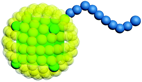 | ||
| Fig. 1 The model of a TNP consists of a soft-shell nanoparticle and a tethered polymer chain. The semitransparent yellow beads (G) represent the soft shell of the nanoparticle, and correspondingly control the nanoparticle shape, the green beads (A) represent the cube, and the blue beads (B) represent the polymer chain. | ||
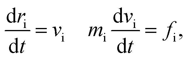
Dissipative particle dynamics (DPD) as a coarse-grained simulation method allows larger time and length scale simulations and takes into account the effect of hydrodynamics. It was introduced in 1992 by Hoogerbrugge and Koelman33 and had been widely used in studies of self-assembly of soft matter systems. In DPD, a coarse-grained bead represents a group of atoms, and all of the DPD beads obey the Newton's equations of motion:34
 | (1) |
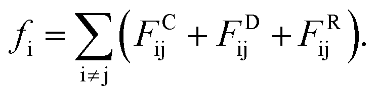
 Actually, we have considered a generic model for polymer tethered nanoparticles; a description on the length, time and temperature scales is shown in ESI.† The bead i receives a total of three forces: they are conservative force FCij, dissipative force FDij and random force FRij:
 | (2) |
These forces act on pairs of beads i and j. They are given by:
| FCij = αijωC(rij)eij, | (3) |
| FDij = −γωD(rij)(vijeij)eij, | (4) |
| FRij = σωR(rij)ξijΔt−1/2eij, | (5) |
| ωD(r) = [ωR(r)]2, | (6) |
| σ2 = 2γkBT. | (7) |
The beads on each tethered polymer chain are connected by harmonic springs with  in which the spring constant C and the equilibrium bond length re are respectively set to 120 and 0.86 to ensure the bond length distribution is within a reasonable range.
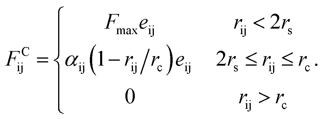
Since in DPD simulations “soft bead” model is generally adopted, it is inevitable that there is bead overlapping and bond crossing in dynamic process, which is however unreasonable in the real system. It may result in problems especially when describing nanoparticles in DPD simulations. In order to ensure that rigid nanoparticles can be reasonably described in our simulations, we use a modified DPD potential between A beads to construct the cubes, in which a rigid core is added to each A bead by redefining the conservative force so that beads cannot penetrate each other. Moreover, we further add a small cube in the centre of cubic head. This double-layered nested structure ensures rigid heads cannot overlap and the chain cannot enter the interior of the rigid body. The modified conservative force in DPD is:36
 | (8) |
In the simulation, polymer chains are modeled hydrophobic and the cubes are hydrophilic. The DPD interaction parameters are shown in Table 1.
| A | B | S | |
|---|---|---|---|
| A | 25 | 55 | αAS |
| B | 55 | 25 | 50 |
| S | αAS | 50 | 25 |
Here the interaction parameter between the same type of beads αii is set as 25. The conservative interaction strength αij can be mapped to Flory–Huggins χ-parameter at ρ = 3:34
| αij ≈ αii + 3.27χij. | (9) |
The simulation box size is 40 × 40 × 40. The side length of cube is 0.78rc. In order to maintain the temperature of the simulation, the simulation timestep is set to dt = 0.008. Each simulation undergoes at least 5 × 10⁶ steps for equilibrium. The concentration of the system is ϕ = 0.05, as defined by
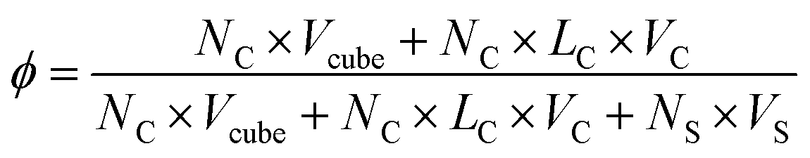 | (10) |
G beads correspond to a bunch of ligand chains grafting on the surface of rigid cubic head, thus our nanoparticle is similar to the one reported by Gang and coworkers.29 The shape of TNP can be tuned by adjusting the interaction between G beads. In an extreme condition that αGG = 0, the grafting density is 0 and the nanoparticle is simply a nanocube. With the increase of the interaction between G beads, the grafting density becomes larger and the shape of the nanohead transforms from cube to sphere gradually. In this way, the regulation of the shape of nanoparticles is achieved, as illustrated in Fig. 2. The interaction parameters of double-layer nested cubic nanoparticles with G particles in the case with αGG = 0 and αAS = 50 are shown in ESI Table S2.†
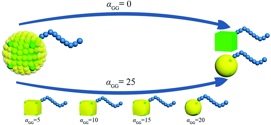 | ||
| Fig. 2 Schematic of the route to regulate the shape of TNP. The colour code is the same as in Fig. 1. | ||
All simulations were performed using GALAMOST package, which is a GPU-accelerated large-scale molecular simulation toolkit developed in our group.37
3 Simulation results and discussion
We first focus on the self-assembly of tethered nanocube with hydrophilic head and hydrophobic chain in dilute solution. As shown in Fig. 3, when αAS = 25 (i.e., the cubic head is kept hydrophilic), the tethered nanocubes self-assemble into dispersed spherical micelles. As chain length increases, the aggregate size increases while the number of aggregates decreases (the number of aggregates is 49, 28, 16, 10 for n = 3, 5, 10, 15). We choose an empirical value 1.25 to draw a circle. If a bead appears in this circle, then it is defined as a neighbor of the center bead in the same aggregate. The rigid hydrophilic cubes distribute on the micelle surface loosely and basically in an equal-distance way to protect the hydrophobic chains. There is no apparent packing mode of these cubes, which means the shape of the cubes does not determine the self-assembly structures. It implies that there would be no difference on micelle structure if spherical hydrophilic nanohead is adopted, and the shape of head nanoparticle is not a big issue on controlling the self-assembly structure.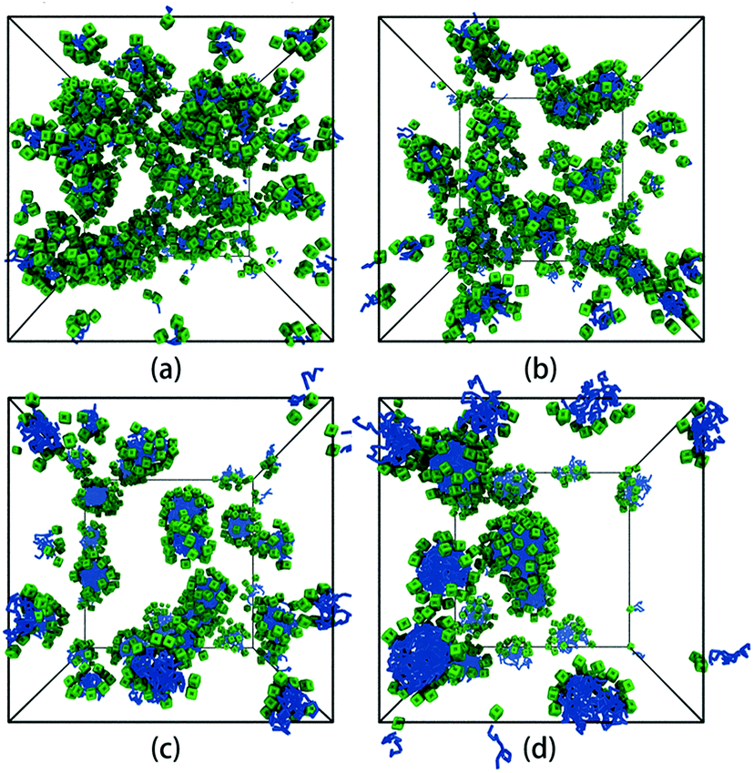 | ||
| Fig. 3 Self-assembled structures with different chain lengths at αAS = 25. (a) n = 3, (b) n = 5, (c) n = 10, (d) n = 15. The solvent beads are not shown for clarity. The colour code is the same as in Fig. 1. | ||
But we can imagine that in cases of decreasing the solubility of nanohead, the micelles start to aggregate or even coalesce. In these cases the shape of rigid nanohead will play a role on determining the self-assembly structures. By systematically varying the interaction between nanocube heads and solvents and the tethered chain length, we obtain the self-assembly structure diagram (Fig. 4) which exhibits interesting aggregation behaviour of tethered nanocubes, as compared with traditional block copolymer system or tethered nanosphere system.25,26
 | ||
| Fig. 4 Self-assembly structure diagram of tethered nanocubes. The horizontal axis represents the interaction between beads in cubic head and solvent, the vertical axis represents the chain length. The colour code is the same as in Fig. 1. The structures highlighted in red square will be shown in Fig. 5 with more details. | ||
As shown in the first column of Fig. 4, when the nanocubes are slightly hydrophobic (i.e., αAS = 30), the originally well-dispersed micelles start to aggregate to form pearl-necklace-like structures38 and the distance between nanocubes decreases. More structural details are shown in ESI Fig. S2.† We also examine the stability of these structures by mimicking annealing process in all DPD simulations. We first increase the temperature to T = 2.5, at which the pearl-necklace-like structure disappears and only some small micelles exist in the solution; then we decrease the temperature back to T = 1.0 slowly by 0.1 per 5 × 10⁵ time steps. After the annealing process, the dispersed micelles re-aggregate into pearl-necklace-like structures quite similar to those obtained in direct simulations, which means the structures shown in the first column of Fig. 4 are the equilibrium structures at the corresponding thermodynamic condition. Similar structures have been observed in experiments.39–41 This type of structure obtained in our simulations is related to the stable interface formed by rigid nanocubes. The packing of the nanocubes on the surface of micelles slows down the surfactant exchange between micelles and the corresponding structure rearrangement; therefore the pearl-necklace-like structure can be stably formed as shown the movie in ESI.†
When the interaction parameter αAS further increases to 40, the nanocube is more hydrophobic. The corresponding self-assembly structures are shown in the second column of Fig. 4. It should be noted that when the whole self-assembly building block is hydrophobic enough (in our case when αAS>30), the equilibrium self-assembly structures can only be obtained after annealing in our simulations. In a typical annealing simulation, after initial equilibration, temperature is increased to T = 2.0 to partially destroy the original self-assembly structures. Then the temperature is decreased to T = 1.0 slowly by 0.1 per 5 × 10⁵ time steps. After that, at least 1 × 10⁶ time steps simulation is performed to obtain the self-assembly structures. In all these four structures shown in the second column of Fig. 4, the nanocubes are packing tightly and surrounding the hydrophobic chains. When the chain is short (n = 3, 5), the self-assembly structures are greatly affected by the shape of nanocubes: the rigid cubic heads are packing in face-to-face manner and form the framework of columnar structures (as shown the movie in ESI†), while the tethered chains distribute in the channels of the framework, similar to the structure obtained in experiments.42 Obviously, the diameter of the channel in the case of n = 3 is smaller than that in the case of n = 5, which implies that it is possible to tune the chain length and type to control the channel size and interior property, and the corresponding material may be used as responsive filters. These framework structures are still quite stable in higher concentrations. For example, as shown in ESI Fig. S3,† we obtain hexagonally arranged columnar structures imbedded in framework formed by nanocubes when the concentration increases to 0.07 for n = 5. The stability of the self-assembly structures is endowed with the shape and volume persistence of the nanocube.43,44 When tethered chain length increases to n = 10, we obtain the handshake structure,45 in which the outer shells formed by nanocubes possess different orientations. A core–shell–corona micelle is obtained in case of n = 15, in which core, shell, and corona are composed of nanocube, tethered chain, and nanocube, respectively. The formation of these two structures is due to the compromise between bending rigidity of layer structure formed by nanocubes favoring a planar configuration and surface tension of the whole structure favoring a spherical configuration.
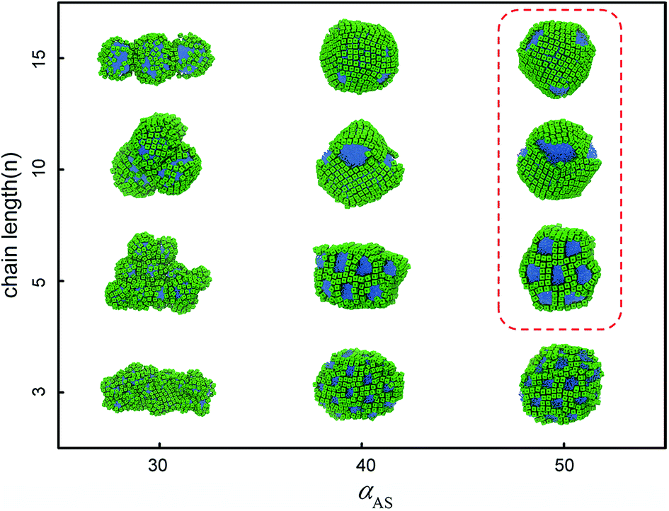
The third column of Fig. 4 shows the self-assembly structures obtained in the cases with αAS = 50. Some details on typical structures viewing in different directions are shown in Fig. 5. In this situation, in the competition between bending rigidity and surface tension, the latter has more influence on determining the self-assembly structures. Therefore, the obtained self-assembly structures are more spherical, and the packing of nanocubes is more ordered (Fig. 5). Since it is impossible to perfectly tessellate spherical surface with squares, there are naturally some packing defects on the surface of more-spherical micelles. An interesting result is shown in Fig. 5a: the competition between surface tension and bending rigidity results in a four-patch micelle. This type of structure has potential applications as mesoscopic building blocks in constructing hierarchical three-dimensional ordered structures at larger length scale.
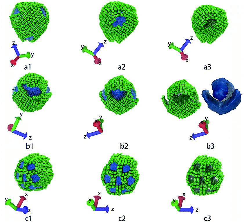 | ||
| Fig. 5 These structures correspond to the highlighted structures in Fig. 4. (a1 ∼ a3) show core–shell–corona micelle with four patches, (b1 ∼ b3) show the handshake structure, (c1 ∼ c3) show the columnar structure. The first and the second columns show structures in different directions. The third column shows only the nanocubes, while (b3) also shows the iso-density surface of tethered chains. The colour code is the same as in Fig. 1. | ||
The results shown in Fig. 3 and 4 clearly demonstrate the influence of nanocube shape and solvent condition on the self-assembly structures of TNPs. In all the cases reported above, the nanocubes are free of any ligand modification; therefore the nanocube shape can have its maximum influence on TNP self-assembly. Actually in a large amount of experiments, the nanoparticle surface is normally protected by grafted ligand chains with controlled grafting density. The interactions between nanocubes are consequently mediated by ligand chains and adsorbed solvent molecules, which will largely influence the self-assembly structures of TNPs. From the coarse-grained point of view, the grafted chains and adsorbed solvent molecules actually form a soft shell around the rigid nanocube (ESI Fig. S4†). Also as illustrated in Fig. 2 together with Fig. S4,† it is possible to represent the effective interaction between grafted chains by tuning the interactions between the beads forming the soft shells of two TNPs. As grafting density increases, the grafted chains are more crowded and the interaction between grafted nanocubes is more repulsive due to larger steric repulsion between chains. Moreover, the number of adsorbed solvent molecules in the grafted chain layer becomes lesser. Therefore, when we increase αGG to represent the increasing repulsion between soft shells in cases of larger grafting densities, we simultaneously increase αGS to reflect more solvent molecules are “repelled” from the grafted chain layers (ESI Fig. S4†).
We take the TNP system A1B15 in the case of αAS = 50 as a reference, for which the representative self-assembly structure of TNPs with bare nanocubes (αGG = 0) is shown in Fig. 5a. We then change αGG = αGS to 5, 10, 15, 20 and 25, to represent the shape of nanocube head transform from cube to superball30 then to sphere, according to the increasing grafting densities (cf. Fig. 2). Key simulation parameters are shown in Table 2, and other parameters are consistent with those used above.
| A | G | B | S | |
|---|---|---|---|---|
| A | 25 | 25 | 55 | 50 |
| G | 25 | αGS | 55 | αGS |
| B | 55 | 55 | 25 | 50 |
| S | 50 | αGS | 50 | 25 |
Fig. 6 shows the representative self-assembly structures of TNP system A1B15 with different interaction parameters between G beads as well as between G and S beads. When αGG and αGS are small, the soft shell of the TNP is more “penetrable” by other soft-shell and solvent beads; it also means the soft shell of TNP is more accessible to solvent, or in another word, more hydrophilic. When αGG and αGS are large, the shell beads are more repulsive to other shell and solvent beads, and the originally cubic head turns to be more spherical. As shown in Fig. 6a, in the case of αGG = αGS = 5 the self-assembly structure of TNPs is dispersed small spherical micelles in solution. Here the surface of nanocube is sparsely grafted with hydrophilic chains, and these so-formed hydrophilic nano-heads help to stabilize the micelle structures. Solvent beads distributed in the grafted chain layer prevent further aggregation and fusion between small micelles. As αGG increases, these small micelles slowly aggregate. It should be noted that in the cases with larger αGG, the soft shell is still hydrophilic, but the eight exposed hydrophobic nanocube corner beads take more and more influence on the self-assembly structures. The increase in αGG corresponds to more and more grafted ligand chains on nanocube surfaces, and these chains can “feel” more entropic repulsion from their neighbors and deviate from the unperturbed state.43 In such situation, if we see the TNP system at nanoparticle level, shells surrounding the nanocubes become harder due to densely grafted ligand chains, at the same time the solvents cannot penetrate into the shell region. Therefore the self-assembly process will be dominated by the hydrophobic interaction between nanocube corner beads as illustrated in Fig. 1. The self-assembly structures turn to be larger micelles with loosely and hexagonally packed spherical nanoparticles distributing at the micelle surfaces (Fig. 6d and e).
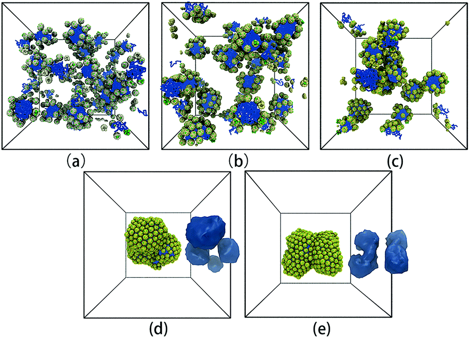 | ||
| Fig. 6 Representative self-assembly structures of TNP system A1B15 with αAS = 50 and (a) αGG = αGS = 5, (b) αGG = αGS = 10, (c) αGG = αGS = 15, (d) αGG = αGS = 20, and (e) αGG = αGS = 25. In (d) and (e), the iso-density surfaces of micelle hydrophobic cores are also shown aside the self-assembly structures. The solvent beads are not shown for clarity. The colour code is the same as in Fig. 1. It should be noted that from (a) to (e), the colour of G beads changes from light yellow to yellow, showing the soft shell turns to be more non-penetrable with increasing grafting density on the nanocube surface. | ||
In order to further explore the nanoparticle distribution at the micelle surface, we have calculated the distances between centers of mass of neighboring TNP heads in each system shown in Fig. 6. We then rank the obtained distances from the small to the large, i.e., for each system we rank the smallest distance between nanoparticles the first, then rank the second smallest distance the second, and so on. The results are shown in Fig. 7. Apparently, with increasing αGG the distance between nanoparticles is gradually decreasing. In the case with αGG = 5, the distance rcm has a broad distribution, characterizing the loosely distributed nanoparticles at micelle surfaces shown in Fig. 6a. In contrast, for αGG = 20 and 25 the distance rcm does not change much with increasing ranking from 20 to 150. It clearly shows the close packing of nanoparticles in these two cases. Statistically, the distance rcm at the same rank is slightly larger in the case with αGG = 25 as compared to that with αGG = 20, which is a natural result of more rigid “shell” in the case with larger αGG. It reasonably reflects that the nanoparticles start to repel each other when the grafting density is pretty large.
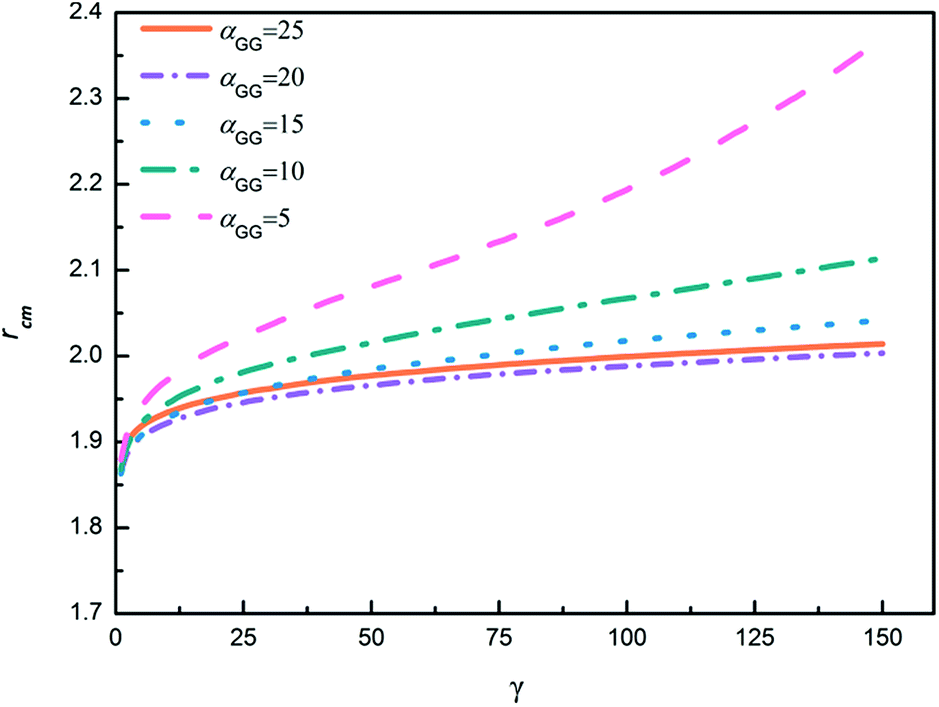 | ||
| Fig. 7 The ranking of center of mass distances between neighboring head nanoparticles. γ represents the ranking of the center of mass distance of nanoparticles (the first 150 rankings are shown). rcm represents the center of mass distance between head nanoparticles. | ||
We have also calculated the radial distribution functions (RDFs) between centres of mass of head nanoparticles in the cases with different values of αGG. For αGG equal to 5, 10 and 15, the RDFs are similar to the one characterizing typical liquid structure, reflecting the fact that the hydrophilic head nanoparticles are homogeneously distributed on the micelle surfaces, as illustrated in Fig. 6a–c. We then focus on RDFs for two extreme cases with different nanoparticle shapes, one is for αGG = 25 and the corresponding self-assembly structure is shown in Fig. 6e, and the other is for αGG = 0 and the corresponding self-assembly structure is shown in Fig. 5a. The RDFs for these two cases are shown in Fig. 8. The first peak positions for the two systems are 1.51 and 2.07, corresponding to the packing of nanocubes and nanospheres, respectively. Apparently the packing of cubic head is more compact than spherical head. The RDF for the system of αGG = 25 has a crested peak signal,46,47 which is a clear evidence for hexagonal packing; i.e., each nanosphere has six neighbouring spheres on a curve surface next to it. For αGG = 0, the main peaks (about at 1.51, 3.01 and 4.49) satisfy the relationship of 1![[thin space (1/6-em)]](https://www.rsc.org/images/entities/char_2009.gif) :2:3, characterizing the closest packing of nanocubes. But it is interesting to see from Fig. 8 that two small peaks (see the arrows) appear between the first and the second main peaks for αGG = 0. As illustrated in Fig. 8, the two small peaks correspond to two diagonal lines of a parallelogram. The nanocubes are packing in this way so that the tension due to bending of the layer can be better relaxed.
:2:3, characterizing the closest packing of nanocubes. But it is interesting to see from Fig. 8 that two small peaks (see the arrows) appear between the first and the second main peaks for αGG = 0. As illustrated in Fig. 8, the two small peaks correspond to two diagonal lines of a parallelogram. The nanocubes are packing in this way so that the tension due to bending of the layer can be better relaxed.
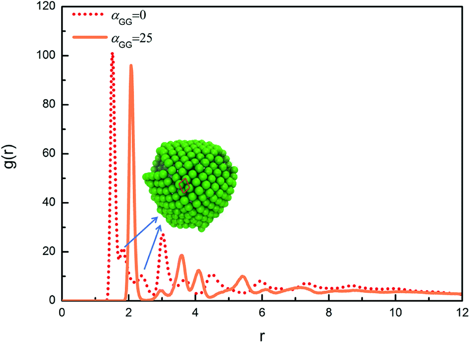 | ||
| Fig. 8 Radial distribution functions g(r) between centres of mass of head nanoparticles for A1B15 in the case with αAS = 50. The snapshot for the equilibrium self-assembly structure in the case of αGG = 0 is shown in the inset. A parallelogram packing of nanocubes is highlighted with read lines in the snapshot. | ||
4 Conclusions
Using dissipative particle dynamics simulation technique, we have studied the self-assembly of tethered nanoparticles with tunable shapes in dilute solution. In the cases that the tethered nanohead is a rigid cube, we have obtained a variety of self-assembly structures with the change of interaction between rigid nanocube and solvent and the length of tethered chains. When the nanocubes are hydrophilic, the self-assembly structures are typically micellar with hydrophobic tethered chains forming the micelle core and nanocubes homogeneously distributing on the micelle surface. The nanocubes start to aggregate when the solvent turns to be poor for both tethered chains and nanocubes, and some regular aggregates can be obtained with characteristic structures depending on the packing modes of nanocubes. The shape of the nanohead does matter in the formation of these aggregated structures.Actually in a large amount of experiments, the nanoparticle surface is normally protected by grafted chains with controlled grafting density. We model the grafted chains and adsorbed solvent molecules using a soft shell surrounding the rigid nanocube. Tuning the interactions between soft shells and between soft shell and solvent is corresponded to changing the grafting density. Starting from an aggregated structure, modifying nanocube surface with some hydrophilic grafted chains (i.e., using small interaction parameters between soft shell beads) immediately helps the TNPs form small micelles. Increasing interaction parameters between soft shell beads mimics the increasing steric repulsion from chain overlapping at larger grafting densities, thus effectively tunes the nanohead from cubic to more spherical. In these cases the self-assembled micelle structures start to coalescence and the packing of nanoparticles on the micelle surface turns from rectangular (typical for cubes) to hexagonal (typical for spheres).
Our simulation results show new possibilities to design the self-assembly structures of TNPs and illustrate the importance of nanoparticle shapes on determining packing modes and structures of TNPs.
Conflicts of interest
There are no conflicts to declare.Acknowledgements
This work was supported by the National Natural Science Foundation of China (21604031, 21534004, 21833008), the National Key R&D Program of China (2018YFB0703701), and JLU-STIRT program at Jilin University.References
- R. L. Marson, T. D. Nguyen and S. C. Glotzer, MRS Commun., 2015, 5, 397–406 CrossRef CAS.
- X. Yu, K. Yue, I. F. Hsieh, Y. Li, X.-H. Dong, C. Liu, Y. Xin, H.-F. Wang, A.-C. Shi, G. R. Newkome, R.-M. Ho, E.-Q. Chen, W.-B. Zhang and S. Z. D. Cheng, Proc. Natl. Acad. Sci. U. S. A., 2013, 110, 10078–10083 CrossRef CAS PubMed.
- Z. Wang, Y. Li, X.-H. Dong, X. Yu, K. Guo, H. Su, K. Yue, C. Wesdemiotis, S. Z. D. Cheng and W.-B. Zhang, Chem. Sci., 2013, 4, 1345–1352 RSC.
- G.-Z. Yin, W.-B. Zhang and S. Z. D. Cheng, Sci. China: Chem., 2017, 60, 338–352 CrossRef CAS.
- D. Conklin, S. Nanayakkara, T.-H. Park, M. F. Lagadec, J. T. Stecher, X. Chen, M. J. Therien and D. A. Bonnell, ACS Nano, 2013, 7, 4479–4486 CrossRef CAS PubMed.
- H. M. Hiep, H. Yoshikawa, M. Saito and E. Tamiya, ACS Nano, 2009, 3, 446–452 CrossRef CAS PubMed.
- C. Sanchez, G. J. d. A. A. Soler-Illia, F. Ribot, T. Lalot, C. R. Mayer and V. Cabuil, Chem. Mater., 2001, 13, 3061–3083 CrossRef CAS.
- S. H. Phillips, T. S. Haddad and S. J. Tomczak, Curr. Opin. Solid State Mater. Sci., 2004, 8, 21–29 CrossRef CAS.
- R. Y. Kannan, H. J. Salacinski, P. E. Butler and A. M. Seifalian, Acc. Chem. Res., 2005, 38, 879–884 CrossRef CAS PubMed.
- X. Yu, S. Zhong, X. Li, Y. Tu, S. Yang, R. M. Van Horn, C. Ni, D. J. Pochan, R. P. Quirk, C. Wesdemiotis, W.-B. Zhang and S. Z. D. Cheng, J. Am. Chem. Soc., 2010, 132, 16741–16744 CrossRef CAS PubMed.
- B. D. Busbee, S. O. Obare and C. J. Murphy, Adv. Mater., 2003, 15, 414–416 CrossRef CAS.
- Y. Sun and Y. Xia, Science, 2002, 298, 2176–2179 CrossRef CAS PubMed.
- K. Yue, C. Liu, K. Guo, X. Yu, M. Huang, Y. Li, C. Wesdemiotis, S. Z. D. Cheng and W.-B. Zhang, Macromolecules, 2012, 45, 8126–8134 CrossRef CAS.
- X. Yu, W.-B. Zhang, K. Yue, X. Li, H. Liu, Y. Xin, C.-L. Wang, C. Wesdemiotis and S. Z. D. Cheng, J. Am. Chem. Soc., 2012, 134, 7780–7787 CrossRef CAS PubMed.
- R. G. Larson, Curr. Opin. Colloid Interface Sci., 1997, 2, 361–364 CrossRef CAS.
- A. J. Schultz, C. K. Hall and J. Genzer, J. Chem. Phys., 2002, 117, 10329–10338 CrossRef CAS.
- X. Zhu, L. Wang, J. Lin and L. Zhang, ACS Nano, 2010, 4, 4979–4988 CrossRef CAS PubMed.
- T. Zhang, C. Fu, Y. Yang and F. Qiu, J. Chem. Phys., 2017, 146, 054902 CrossRef PubMed.
- S. C. Glotzer, M. A. Horsch, C. R. Iacovella, Z. Zhang, E. R. Chan and X. Zhang, Curr. Opin. Colloid Interface Sci., 2005, 10, 287–295 CrossRef CAS.
- X. Zhang, E. R. Chan and S. C. Glotzer, J. Chem. Phys., 2005, 123, 184718 CrossRef PubMed.
- E. R. Chan, L. C. Ho and S. C. Glotzer, J. Chem. Phys., 2006, 125, 064905 CrossRef PubMed.
- X. Zhang, Z. L. Zhang and S. C. Glotzer, Nanotechnology, 2007, 18, 115706 CrossRef.
- M. A. Horsch, Z. Zhang and S. C. Glotzer, Nano Lett., 2006, 6, 2406–2413 CrossRef CAS PubMed.
- C. R. Iacovella, M. A. Horsch, Z. Zhang and S. C. Glotzer, Langmuir, 2005, 21, 9488–9494 CrossRef CAS PubMed.
- S. Ma, Y. Hu and R. Wang, Macromolecules, 2015, 48, 3112–3120 CrossRef CAS.
- C. Wang, S. Ma, Y. Hu and R. Wang, Langmuir, 2017, 33, 3427–3433 CrossRef CAS PubMed.
- O. Gang and Y. Zhang, ACS Nano, 2011, 5, 8459–8465 CrossRef CAS PubMed.
- J.-W. Yoo and S. Mitragotri, Proc. Natl. Acad. Sci. U. S. A., 2010, 107, 11205–11210 CrossRef CAS PubMed.
- Y. Zhang, F. Lu, D. van der Lelie and O. Gang, Phys. Rev. Lett., 2011, 107, 135701 CrossRef PubMed.
- R. Ni, A. P. Gantapara, J. de Graaf, R. van Roij and M. Dijkstra, Soft Matter, 2012, 8, 8826–8834 RSC.
- T. D. Nguyen, E. Jankowski and S. C. Glotzer, ACS Nano, 2011, 5, 8892–8903 CrossRef CAS PubMed.
- C. X. Du, G. van Anders, R. S. Newman and S. C. Glotzer, Proc. Natl. Acad. Sci. U. S. A., 2017, 114, E3892–E3899 CrossRef CAS PubMed.
- P. J. Hoogerbrugge and J. M. V. A. Koelman, Europhys. Lett., 1992, 19, 155–160 CrossRef.
- R. D. Groot and P. B. Warren, J. Chem. Phys., 1997, 107, 4423–4435 CrossRef CAS.
- P. Español and P. Warren, Europhys. Lett., 1995, 30, 191–196 CrossRef.
- H. Liu, Y.-H. Xue, H.-J. Qian, Z.-Y. Lu and C.-C. Sun, J. Chem. Phys., 2008, 129, 024902 CrossRef PubMed.
- Y.-L. Zhu, H. Liu, Z.-W. Li, H.-J. Qian, G. Milano and Z.-Y. Lu, J. Comput. Chem., 2013, 34, 2197–2211 CrossRef CAS.
- S.-C. Chen, S.-W. Kuo and F.-C. Chang, Langmuir, 2011, 27, 10197–10205 CrossRef CAS PubMed.
- J. Wei, B. H. Tan, Y. Bai, J. Ma and X. Lu, J. Phys. Chem. B, 2011, 115, 1929–1935 CrossRef CAS PubMed.
- K.-Y. Yoon, I.-H. Lee, K. O. Kim, J. Jang, E. Lee and T.-L. Choi, J. Am. Chem. Soc., 2012, 134, 14291–14294 CrossRef CAS PubMed.
- L. Hong, Z. Zhang, Y. Zhang and W. Zhang, J. Polym. Sci., Part A: Polym. Chem., 2014, 52, 2669–2683 CrossRef CAS.
- H. He, S. Chen, X. Tong, Z. An, M. Ma, X. Wang and X. Wang, Langmuir, 2017, 33, 13332–13342 CrossRef CAS PubMed.
- X.-H. Dong, B. Ni, M. Huang, C.-H. Hsu, Z. Chen, Z. Lin, W.-B. Zhang, A.-C. Shi and S. Z. D. Cheng, Macromolecules, 2015, 48, 7172–7179 CrossRef CAS.
- X.-H. Dong, B. Ni, M. Huang, C.-H. Hsu, R. Bai, W.-B. Zhang, A.-C. Shi and S. Z. D. Cheng, Angew. Chem., Int. Ed., 2016, 55, 2459–2463 CrossRef CAS PubMed.
- H. Chen and E. Ruckenstein, Soft Matter, 2012, 8, 8911–8916 RSC.
- Z.-W. Li, L.-J. Chen, Y. Zhao and Z.-Y. Lu, J. Phys. Chem. B, 2008, 112, 13842–13848 CrossRef CAS PubMed.
- H. Zewdie, Phys. Rev. E, 1998, 57, 1793–1805 CrossRef CAS.
Footnote |
| † Electronic supplementary information (ESI) available. See DOI: 10.1039/c8ra09635j |
| This journal is © The Royal Society of Chemistry 2019 |