
 Open Access Article
 This Open Access Article is licensed under a Creative Commons Attribution-Non Commercial 3.0 Unported Licence
Cobalt ferrite supported on reduced graphene oxide as a T2 contrast agent for magnetic resonance imaging†
Amira Alazmi *ad,
Venkatesh Singaravelub,
Nitin M. Batraa,
Jasmin Smajica,
Mram Alyamic,
Niveen M. Khashabc and
Pedro M. F. J. Costa*a
*ad,
Venkatesh Singaravelub,
Nitin M. Batraa,
Jasmin Smajica,
Mram Alyamic,
Niveen M. Khashabc and
Pedro M. F. J. Costa*a
aKing Abdullah University of Science and Technology (KAUST), Physical Science and Engineering Division, Thuwal 23955-6900, Saudi Arabia. E-mail: amirh.aalazmy@kaust.edu.sa; pedro.dacosta@kaust.edu.sa
bKing Abdullah University of Science and Technology (KAUST), Core Labs, Thuwal, 23955-6900, Saudi Arabia
cSmart Hybrid Materials (SHMs) Laboratory, Advanced Membranes and Porous Materials Center, King Abdullah University of Science and Technology, Thuwal 23955-6900, Kingdom of Saudi Arabia
dUniversity of Hafr Al Batin, University Colleges at Nairiyah, Nairiyah, Saudi Arabia
First published on 21st February 2019
Abstract
Nanoscaled spinel-structured ferrites bear promise as next-generation contrast agents for magnetic resonance imaging. However, the small size of the particles commonly leads to colloidal instability under physiological conditions. To circumvent this problem, supports onto which the dispersed nanoparticles can be anchored have been proposed. Amongst these, flakes of graphene have shown interesting performance but it remains unknown if and how their surface texture and chemistry affect the magnetic properties and relaxation time (T2) of the ferrite nanoparticles. Here, it is shown that the type of graphene oxide (GO) precursor, used to make composites of cobalt ferrite (CoFe2O4) and reduced GO, influences greatly not just the T2 but also the average size, dispersion and magnetic behaviour of the grafted nanoparticles. Accordingly, and without compromising biocompatibility, a judicious choice of the initial GO precursor can result in the doubling of the proton relaxivity rate in this system.
1. Introduction
In recent years, various types of nanoparticles (NPs) have been investigated as potential magnetic resonance imaging (MRI) contrast agents. At the nanoscale, there is a higher probability to observe particles that constitute a single magnetic domain, this resulting in superparamagnetic behaviour. In fact, superparamagnetism is assumed to be the most favourable condition for solid-state contrast agents, as the uniform directionality of the field will maximize the magnetization strength. To achieve this maximal magnetic moment, the particle must remain below a certain size threshold (upwards from which a multi-domain regime occurs).1 Superparamagnetism is marked by the absence of remnant magnetization after removal of external fields. When applied to NPs, this property promotes colloidal stability and, most importantly, avoids aggregation (which is key for NPs used in biomedical applications).2 However, with size reduction (and the associated increase in surface-to-volume ratio), some unintended phenomena become more pronounced. These can deleteriously affect the superparamagnetic response of a nanoparticle and include agglomeration, spin-glass-like behaviour, non-collinear spins and spin canting.2,3Spinel ferrite compounds MFe2O4 (M = Mn, Co, Ni, Fe, etc.) are a class of metal oxide materials that offer a broad spectrum of applications.4,5 In particular, cobalt ferrite (CoFe2O4) NPs have been studied as signal enhancement agents in MRI because of their large Curie temperature, moderate saturation magnetization and notable magneto-crystalline anisotropy.6,7 Recently, nanocomposites that consist of GO mixed with CoFe2O4 NPs were reported.8,9 The GO substrate not only anchors the NPs (avoiding aggregation and/or sedimentation) but also has a fairly biocompatible surface.8
Although GO is a valid supporting matrix, it is chemically reactive (because of the profusion of grafted functional groups). Under physiological conditions, this could represent a liability (e.g. risk of early deactivation). On the other hand, its counterpart, the reduced graphene oxide (rGO), retains the flaky layered structure of GO and is more inert. To the best of our knowledge, there are no reports regarding the proton relaxivity value obtained in CoFe2O4–rGO composites. Herein, it is described how the MRI contrast is changed when the oxide loading and the type of graphene are varied in composites of cobalt ferrite nanoparticles grafted to rGO. To do this, the morphology, structure, chemistry, magnetic properties and cytotoxicity of two sets of rGO composites with CoFe2O4 loadings comprised between 5–30 wt% were considered.
2. Experimental
2.1 Synthesis of the GO precursor
The GO was prepared from graphite powder (Alfa Aesar, <50 μm) through one of two commonly used chemical processes: the Hummers' (HGO)10 or the so-called improved Hummers' (IGO)11 method. The hydrothermally reduced GOs were prepared as follows: 100 mg of HGO (or IGO) powder was dispersed in 40 mL of deionized water and stirred for 24 h to form an aqueous dispersion. The mixture was then transferred to a 50 mL Teflon-lined stainless steel autoclave, which was placed in an oven at 180 °C for 24 h. The product was collected, centrifuged and washed several times with deionized water and freeze-dried under reduced pressure (0.133 mbar) for 24 h in a Labconco Free Zone system. The rGO prepared by the Hummers' method is hereafter designated as rHGO, and that prepared by the improved Hummers' method is designated as rIGO.2.2 Synthesis of the CoFe2O4–rGO composites
CoFe2O4–rGO composites with metal oxide loadings of 0, 5, 10, 16 and 30 wt% were prepared by a hydrothermal method using water as a solvent. In a typical synthesis procedure, 100 g of HGO (or IGO) was dispersed in 30 mL of water with sonication for 12 h. Stoichiometric amounts of Co(NO3)2·6H2O (Sigma-Aldrich) and Fe(NO3)3·9H2O (Sigma-Aldrich) were added to the GO aqueous dispersion, followed by stirring at room temperature. The pH of the reaction mixture was adjusted to 10 by adding the needed volume of a NH3·H2O solution. The mixture was then transferred to a 50 mL Teflon-lined stainless steel autoclave and kept in an oven at 180 °C for 24 h. The product was collected, centrifuged, washed several times with deionized water and freeze-dried under reduced pressure (0.133 mbar) for 24 h. For reference, pure CoFe2O4 NPs were synthesized as follows: 0.5 g of Co(NO3)2·6H2O and 1.37 g of Fe(NO3)3·9H2O were dissolved in 30 mL of water. The pH of the reaction mixture was subsequently adjusted to 10 by adding the needed volume of a NH3·H2O solution. The mixture was then transferred to a 50 mL Teflon-lined stainless steel autoclave and kept in an oven at 180 °C for 24 h. The product was collected, centrifuged, washed several times with deionized water and freeze-dried under reduced pressure (0.133 mbar) for 24 h.3. Measurements
3.1 Characterization techniques
All composite materials were characterized by X-ray powder diffraction (XRD; Bruker, D8 Advance) with Cu Kα radiation (λav = 1.5418 Å). The morphology and size of the carbonaceous flakes and metal oxide NPs were examined by transmission electron microscopy (TEM; Thermo Fisher Scientific Tecnai BioTwin, 120 keV). SEM micrographs of the powder samples were acquired with a Quanta FEG scanning electron microscope (Thermo Fisher Scientific) operated at 5 kV. Energy-dispersive X-ray spectroscopy (EDS) was performed using an EDS Genesis detector (EDAX Inc.). The Fourier transform infrared (FTIR) spectral analyses were carried out with a Thermo Scientific spectrometer (Nicolet iS10). Raman studies were performed using a WITec Alpha 300 RA spectrometer employing an excitation wavelength of 488 nm. X-ray photoelectron spectroscopy (XPS) studies were carried out in a Kratos Axis Ultra DLD spectrometer equipped with a monochromatic Al Kα X-ray source (hν = 1486.6 eV) operating at 150 W, a multi-channel plate and delay line detector under a vacuum of ∼10−9 mbar. The survey and high-resolution XPS spectra were collected at fixed analyzer pass energies of 160 eV and 20 eV, respectively. Samples were mounted in floating mode in order to avoid differential charging. Zeta (ζ)-potential analyses were performed using a Malvern Zetasizer Nano ZS instrument. The magnetic properties of the composites were characterized using a superconducting quantum interference device (SQUID)-vibrating sample magnetometer (VSM) system (Quantum Design USA) equipped with a highly sensitive (10−8 emu) sensor. The magnetization measurements were carried out on powder samples using straw holders by varying the magnetic field from −3 T to +3 T. For the magnetic resonance imaging (MRI) studies, different concentrations of the composites were dispersed in 2% agarose (w/v) gels, whereas a blank gel was used as a reference. The T2 relaxivity of water protons in the presence of the as-synthesized composites was measured using a Bruker 500SWB spectrometer integrating a superwide-bore 11.7 T magnet resonating at 500 MHz. The relaxivity r2 is the slope of the line fitted to the 1/T2 concentrations (C) plot, which is related to T2 through eqn (1):
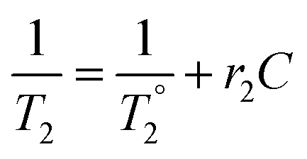 | (1) |
 is the relaxation time in the absence of the contrast agent. From eqn (1), T2 is revealed as a concentration-dependent term. However, r2 is a concentration-independent term. In fact, a contrast agent with a large r2 value can shorten the T2 substantially with a smaller concentration increment. The relaxivity values (r2) of the water protons were calculated using eqn (1). The Fe concentrations were obtained from inductively coupled plasma optical emission spectrometry (ICP-OES) using a Varian 720-ES spectrometer. Typically, 10 mg of sample powder was mixed in 4 mL of concentrated HNO3 and 1 mL of H2O2 (30%). Subsequently, this mixture was placed in closed Teflon vessels and digested for 40 min with the assistance of microwaves (1000 W, 200 °C).
3.2 In vitro cytotoxicity
HeLa cells were seeded in 96-well plates (6 × 10³ cells per well) in 100 μL of a Dulbecco's modified Eagle's medium (DMEM) supplemented with 10% foetal bovine serum (FBS) and 1% penicillin–streptomycin at 37 °C in a 5% CO2 humidified atmosphere for 24 h. After cell attachment, the cells were washed with Dulbecco's phosphate buffer solution (PBS) and incubated at different concentrations (5, 10, 20, 25 and 50 μg mL−1) of rIGO, rHGO, 30 wt% CoFe2O4–rHGO and 30 wt% CoFe2O4–rIGO in the DMEM for 24 h at 37 °C. The culture medium was then discarded, the Cell Counting Kit-8 (CCK)-8 solution was added into the wells, and the plate was incubated for an additional 4 h in darkness. The absorbance values were measured at 450 nm using a microplate spectrophotometer (xMark™ Microplate Absorbance Spectrophotometer).4. Results and discussion
4.1 Structural and chemical characterization
First, the shape, size, composition and structure of the spinel-structured ferrite NPs and their respective composites were analysed. A tableau of representative TEM micrographs for the entire set of synthesized materials is shown in Fig. 1. The micrographs of the CoFe2O4–rGO composites (Fig. 1a–h) show 5–13 nm NPs distributed randomly on the surface and at the edges of the rGO sheets. In all cases, the presence of C, O, Fe and Co was confirmed by EDS analysis (Fig. SI1†). Additionally, the bulk Fe content of each sample was measured with ICP-OES. As expected, the concentration of iron increased as a function of particle loading in the composites, attaining a maximum for the 30 wt% CoFe2O4–rIGO (Table SI1†). Throughout the set of composites, the morphologies of the substrate sheets (rGO) are similar but the size of the NPs (CoFe2O4) differs. The bar charts showing the size distribution were constructed from the statistical analysis of TEM images, with the number of NPs counted exceeding 100. The average particle size (Dav) and corresponding standard deviation (σ) are also presented in Fig. 1 and Table SI2.† Generally, the CoFe2O4 particles grafted onto the flakes grew as the loading concentration increased (from 5 to 30 wt%); this growth occurred irrespective of the type of GO precursor employed. However, for equivalent loadings, the average particle size was smaller in the rHGO composites than in the rIGO ones. Following the analysis of oxygen content by XPS (Fig. SI2†), a possible explanation is that the sheets of the IGO precursor contain a greater number of oxygenated groups11–13 that, upon the reduction reaction, produce a larger amount of gaseous species (more on this later in the text). Higher pressures in the autoclave favour both an increase in the nucleation rate and faster growth kinetics of the CoFe2O4 NPs.14 Altogether, as the optimal loading and resulting particle size are concerned, it can be stated that it is not just the metal oxide precursor concentration that matters but also the type of GO precursor that is used.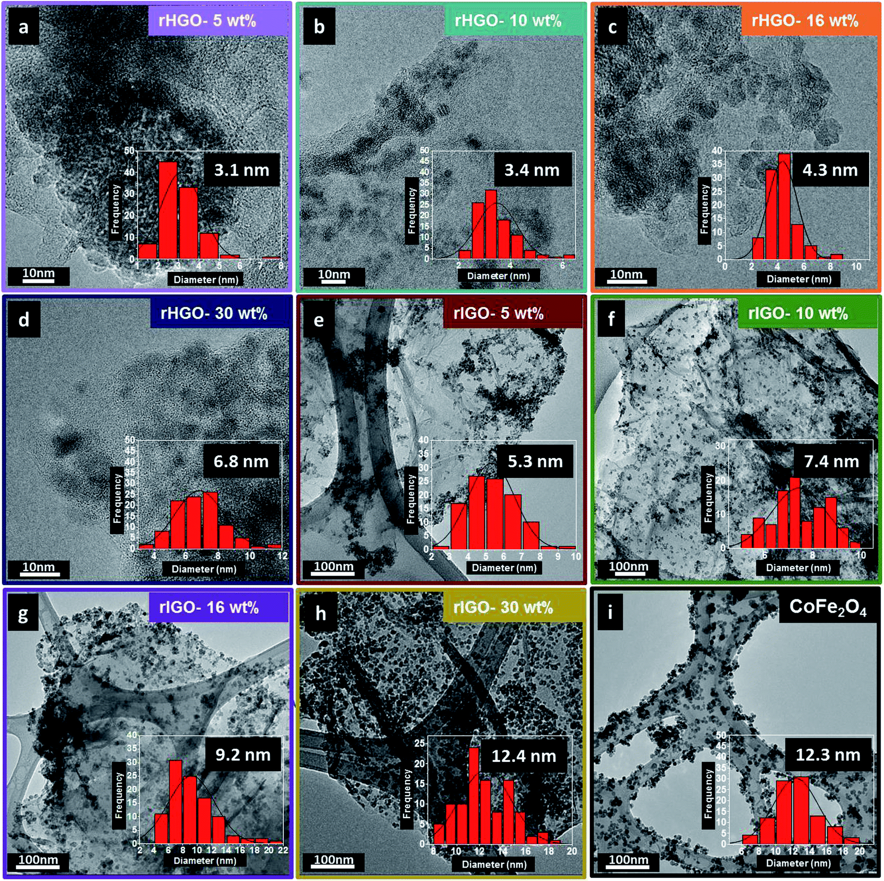 | ||
| Fig. 1 (a–d) TEM images (inset: NPs size distribution histogram and average size) of the CoFe2O4–rHGO composites with 5, 10, 16 and 30 wt% CoFe2O4, respectively; (e–h) TEM images (inset: NPs size distribution histogram and average size) of the CoFe2O4–rIGO composites with 5, 10, 16 and 30 wt% CoFe2O4, respectively; (i) TEM image (inset: NPs size distribution histogram and average size) of the pure CoFe2O4 NPs. | ||
The XRD patterns of the NPs, pure rGOs and their respective composites are presented in Fig. 2. The diffractogram of the CoFe2O4 NPs confirms the expected cubic spinel phase (space group 227 or Fd![[3 with combining macron]](https://www.rsc.org/images/entities/char_0033_0304.gif) m, ICDD card 03-0864). The patterns of the rHGO (Fig. 2a) and rIGO (Fig. 2b) also follow the general profile for these materials.15,16 Interestingly, in the case of the composites, the diffractograms of the rHGOs are dominated by the peaks of the carbonaceous matrix, whereas the rIGOs go through an inversion from sheets to particles, upwards from 16 wt% loadings. In fact, for the maximum loading tested (30 wt%), the rIGO peak at 2θ ≈ 25° becomes overshadowed by those of the grafted NPs (which are similar, in shape and intensity ratios, to the peaks of the standalone NPs). This result concurs with the more localized TEM observations and extends them to the bulk powder. Effectively, the 30 wt% CoFe2O4–rIGO composite is the one with the highest loading efficiency and contains NPs whose crystallinity and size match those of the standalone NPs.
m, ICDD card 03-0864). The patterns of the rHGO (Fig. 2a) and rIGO (Fig. 2b) also follow the general profile for these materials.15,16 Interestingly, in the case of the composites, the diffractograms of the rHGOs are dominated by the peaks of the carbonaceous matrix, whereas the rIGOs go through an inversion from sheets to particles, upwards from 16 wt% loadings. In fact, for the maximum loading tested (30 wt%), the rIGO peak at 2θ ≈ 25° becomes overshadowed by those of the grafted NPs (which are similar, in shape and intensity ratios, to the peaks of the standalone NPs). This result concurs with the more localized TEM observations and extends them to the bulk powder. Effectively, the 30 wt% CoFe2O4–rIGO composite is the one with the highest loading efficiency and contains NPs whose crystallinity and size match those of the standalone NPs.
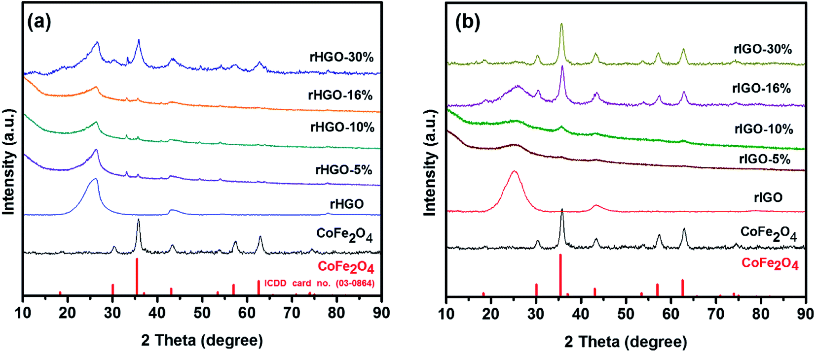 | ||
| Fig. 2 XRD patterns for: (a) CoFe2O4, rHGO and CoFe2O4–rHGO composites with 5, 10, 16 and 30 wt% CoFe2O4; (b) CoFe2O4, rIGO and CoFe2O4–rIGO composites with 5, 10, 16 and 30 wt% CoFe2O4. | ||
To confirm the successful synthesis of the CoFe2O4 NPs and the structural constancy of the rGOs in the composites, Raman spectra were acquired for all of the samples (Fig. 3). In the spectrum of the standalone particles, a set of bands between 100 cm−1 and 750 cm−1 were observed, identified as the characteristic peaks of the CoFe2O4 spinel structure; specifically, the A1g + Eg + 3T2g resonant modes.17 The spectra of the rGOs had similar profiles, showing the expected D and G bands of disordered carbon. The intensity ratio between these bands differed slightly, with the rIGO showing a more preponderant D band. Likewise, in the spectra of all of the CoFe2O4–rGO composites, the D and G bands of the support dominated, with the peaks of the NPs noticeable only in the samples with 30 wt% loading. Interestingly, the frequencies of the D (1328 cm−1) and G (1598 cm−1) bands do not change with loading or type of rGO. However, when inspecting the set of spectra for rHGO, we observed that their intensity ratio changed from the parent flakes to the composites. This change could be due to the hydrothermal synthesis conditions, which may induce additional exfoliation and expose more defects in the graphene lattice.11–13 Altogether, no visible differences were observed in the Raman spectra of the composites derived from HGO or IGO.
 | ||
| Fig. 3 Raman spectra for: (a) rHGO, CoFe2O4 and CoFe2O4–rHGO composites with 5, 10, 16 and 30 wt% CoFe2O4, respectively; (b) rIGO, CoFe2O4 and CoFe2O4–rIGO composites with 5, 10, 16 and 30 wt% CoFe2O4, respectively. | ||
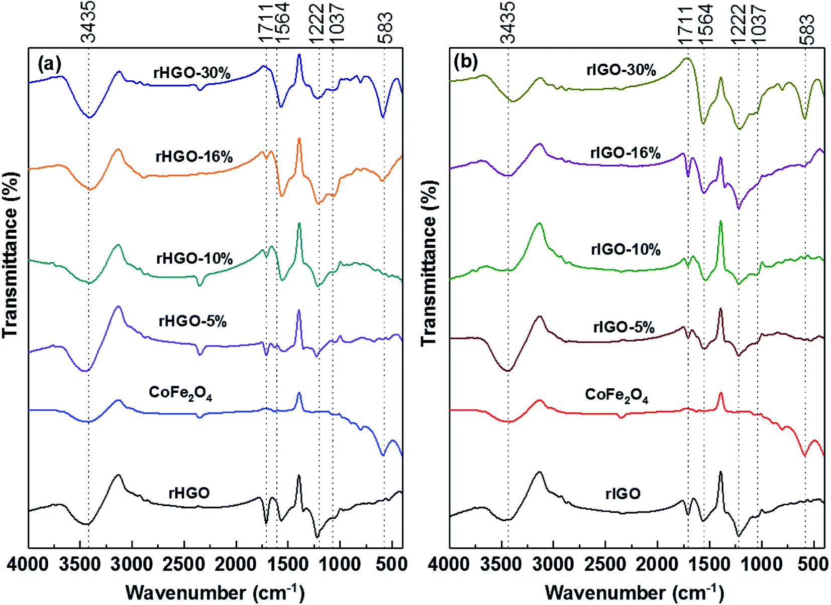
Infrared spectroscopy was used to verify the integrity of the NPs and to identify major variations in the chemical moieties attached to the carbonaceous sheets. As shown in Fig. 4, all of the FTIR spectra (CoFe2O4 NPs included) exhibited a broad peak at approximately 3435 cm−1. This peak corresponds to the –OH stretching vibration, a fingerprint for surface-adsorbed water.18 In the spectrum of the standalone CoFe2O4 NPs, the peak at 583 cm−1 is a spectral fingerprint derived from the Fe(Co)–O stretching vibration (it is also observed, at the same frequency, in the spectrum of bulk CoFe2O4).19–22 The spectra of the two rGOs are similar. The peak located at ∼1711 cm−1 is attributed to the C![[double bond, length as m-dash]](https://www.rsc.org/images/entities/char_e001.gif) O stretching vibration,23 whereas the broad peak at ∼1564 cm−1 likely originates from the bending vibrations of adsorbed water molecules and the skeletal CC vibrations of non-oxidized graphitic domains.24–27 The peaks at 1222 cm−1 and 1037 cm−1 could belong to the asymmetrical and symmetrical C–O aromatic stretching vibrations of epoxy groups, respectively (the latter could also be derived from a C–N stretch).19,28 A comparison of the two sets of composites reveals that the IR spectral signature is mostly independent of the rGO used. Nonetheless, these results, whilst indicating a bulk-level similarity in the main types of organic moieties grafted onto the carbonaceous sheets, do not preclude variations in surface chemistry such as concentration and dispersion of the moieties, as previously shown.12 Interestingly, for the two 30 wt% rGO composites, the CO stretching vibration is suppressed, whereas the NPs signature peak becomes quite prominent.
O stretching vibration,23 whereas the broad peak at ∼1564 cm−1 likely originates from the bending vibrations of adsorbed water molecules and the skeletal CC vibrations of non-oxidized graphitic domains.24–27 The peaks at 1222 cm−1 and 1037 cm−1 could belong to the asymmetrical and symmetrical C–O aromatic stretching vibrations of epoxy groups, respectively (the latter could also be derived from a C–N stretch).19,28 A comparison of the two sets of composites reveals that the IR spectral signature is mostly independent of the rGO used. Nonetheless, these results, whilst indicating a bulk-level similarity in the main types of organic moieties grafted onto the carbonaceous sheets, do not preclude variations in surface chemistry such as concentration and dispersion of the moieties, as previously shown.12 Interestingly, for the two 30 wt% rGO composites, the CO stretching vibration is suppressed, whereas the NPs signature peak becomes quite prominent.
 | ||
| Fig. 4 FTIR spectra for: (a) rHGO, CoFe2O4 and CoFe2O4–rHGO composites with 5, 10, 16 and 30 wt% CoFe2O4; (b) rIGO, CoFe2O4 and CoFe2O4–rIGO composites with 5, 10, 16 and 30 wt% CoFe2O4. | ||
Taken together, the TEM and XRD analyses show clear trends in the composite samples as the density and size of NPs differed with the type of rGO. However, the vibrational spectroscopy studies (Raman and FTIR) did not identify variations as a function of the rGO used. In these circumstances, the concentration, dispersion and sterical availability of grafted functional groups such as hydroxyl, epoxy, and carboxylic acid groups (which are commonly found on the surface and edges of GO sheets)27,29,30 are the main reason for the observed variations. This explanation concurs with our previous observation of a greater degree of surface oxidation and specific surface area for the rIGO powder.12 With respect to the suppression of the CO mode in the composites with the highest CoFe2O4 loading (cf. FTIR spectra), these organic moieties can plausibly act as preferential anchor sites to nucleate the NPs. One possible mechanism is the formation of carboxylate anions (due to the addition of aqueous NH3 to adjust the pH to 10) which localizes the negative charge needed to trap the divalent transition metal ion, Co2+.19,29 With prolonged exposure to heat, the greater concentration of organic moieties at the rIGO surface results in more ammonium that boils and contributes to pressure build-up in the autoclave. This increase in pressure favours the kinetics of spinel formation explaining the faster growth rates and larger average size of the NPs in the rIGO composites.
4.2 Magnetic properties
Surface and finite-size effects play a key role in the magnetic properties of NPs.31,32 Given that a direct correlation of magnetization and particle size has been reported in several ferrite systems,33–35 establishing this effect for the present composites is important. The magnetic properties of the standalone CoFe2O4 NPs, the rGOs and the CoFe2O4–rGO composites were studied at room temperature using magnetic field strengths in the range from −30![[thin space (1/6-em)]](https://www.rsc.org/images/entities/char_2009.gif) 000 Oe to 30000 Oe (Fig. 5 and SI3†). The field-dependent magnetization hysteresis (M vs. H) measurements show that the standalone NPs are ferromagnetic (Fig. 5a). The saturation magnetization (Ms) is approximately 56 emu g−1, which agrees well with the value reported in the literature.36 By contrast, the blank rGOs are diamagnetic (Fig. SI4†). With respect to the various CoFe2O4–rGO composites, and in addition to the curves in Fig. 5b and c, the magnetization at 30000 Oe (MH=30000 Oe) and coercivity (Hc) are summarized in Table SI3.† On the whole, the MH=30000 Oe and Hc values obtained for the CoFe2O4–rIGO composites were consistently higher than those for the corresponding rHGOs. Furthermore, most of the composites showed negligible remanence (Mr) and Hc, implying a superparamagnetic response. The exceptions were the CoFe2O4–rIGO powders with the two highest ferrite loadings. For these samples, ferromagnetism was identified, along with relatively large Hc values of 87 Oe and 97 Oe for the 16 wt% and 30 wt% loadings, respectively. Finally, the combined results for the field-dependent magnetization and the average ferrite particle size in each composite confirm the aforementioned magnetization–size correlation for the two rGO sets (Fig. SI5†).
000 Oe to 30000 Oe (Fig. 5 and SI3†). The field-dependent magnetization hysteresis (M vs. H) measurements show that the standalone NPs are ferromagnetic (Fig. 5a). The saturation magnetization (Ms) is approximately 56 emu g−1, which agrees well with the value reported in the literature.36 By contrast, the blank rGOs are diamagnetic (Fig. SI4†). With respect to the various CoFe2O4–rGO composites, and in addition to the curves in Fig. 5b and c, the magnetization at 30000 Oe (MH=30000 Oe) and coercivity (Hc) are summarized in Table SI3.† On the whole, the MH=30000 Oe and Hc values obtained for the CoFe2O4–rIGO composites were consistently higher than those for the corresponding rHGOs. Furthermore, most of the composites showed negligible remanence (Mr) and Hc, implying a superparamagnetic response. The exceptions were the CoFe2O4–rIGO powders with the two highest ferrite loadings. For these samples, ferromagnetism was identified, along with relatively large Hc values of 87 Oe and 97 Oe for the 16 wt% and 30 wt% loadings, respectively. Finally, the combined results for the field-dependent magnetization and the average ferrite particle size in each composite confirm the aforementioned magnetization–size correlation for the two rGO sets (Fig. SI5†).
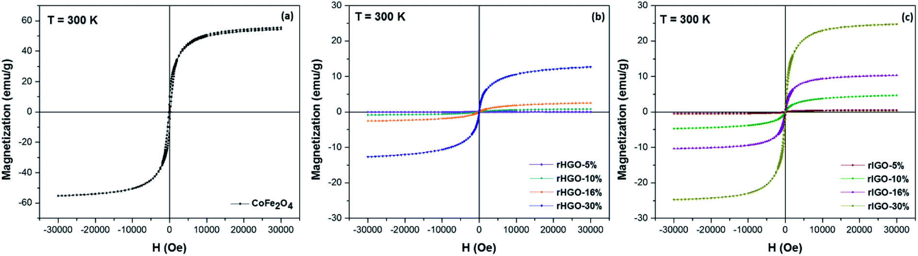 | ||
| Fig. 5 Field-dependent magnetic hysteresis loops for: (a) pure CoFe2O4 NPs, (b) CoFe2O4–rHGO composites and (c) CoFe2O4–rIGO composites, measured at room temperature. | ||
To further understand the correlation of magnetization to particle size/loading and to explain the superparamagnetic-to-ferromagnetic transition observed in the CoFe2O4-rIGO composites, temperature-dependent magnetization data were acquired under zero-field-cooled (ZFC) and field-cooled (FC) conditions (Fig. 6). Initially, each sample was cooled under a nominal zero field to 5 K. Then, a 1 kOe field was applied. The magnetization data (ZFC) were collected as the sample was warmed to 300 K, and the FC data were collected as the sample was cooled to 5 K (at 1 kOe). A substantial separation between the ZFC and FC curves was observed for the composite samples. The peak in the ZFC curve (Fig. 6a) denotes the average blocking temperature (TB). In the case of the rHGO composites (Fig. 6a–d), the TB value increases linearly with CoFe2O4 loading (71 K, 105 K, 133 K and 215 K for the 5 wt%, 10 wt%, 16 wt% and 30 wt%, respectively) but remains well below room temperature. For the rIGO composites (Fig. 6e–h), the TB increases from the sample with 5 wt% (135 K) to the sample with 10 wt% loading (179 K). However, at higher loadings, the blocking disappears and the ZFC–FC curves resemble that of the standalone CoFe2O4 NPs (Fig. 6i). Overall, when comparing the TB obtained (where applicable) with the loadings and the average size of NPs in the two sets of rGO composites, a linear correlation is inferred between TB and the size of the CoFe2O4 particles.
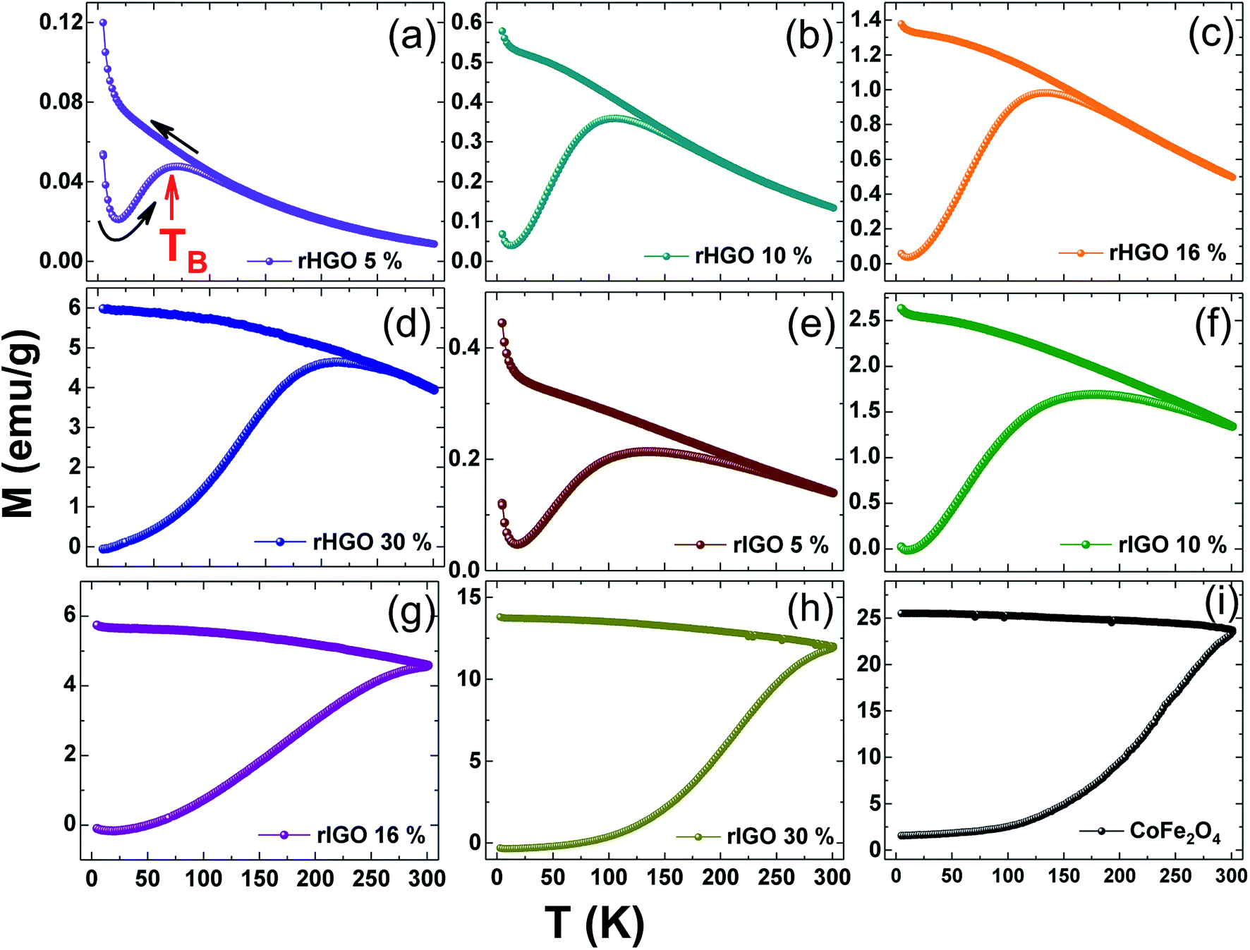 | ||
| Fig. 6 The ZFC–FC curves for the rHGO (panels a–d) and rIGO (panels e–h) composites with increased loading of CoFe2O4. Reference data for the pure CoFe2O4 powder are shown in panel (i). The average blocking temperature (TB), which is the peak of the ZFC curve, is indicated by an arrow in panel (a). | ||
The critical size for the single-to-multidomain magnetic transition of a nanoparticle (r0) can be calculated by r0 = (6kBTB/K)1/3, where kB is the Boltzmann constant, TB is the maximum blocking temperature, and K is the anisotropy constant. For CoFe2O4, the reported critical size is ∼10 nm.37 The ZFC–FC curves in Fig. 6 show that the critical size was not attained for the rHGO composites because a TB is still observed for the highest loading (30 wt%). This behaviour contrasts to that of the rIGO composites, where a critical size of 9.4 nm was identified for the 16 wt% loading (cf. absence of a TB). Conceivably, the true r0 may be smaller because no loadings in the interval 10–16 wt% (7.5–9.4 nm) were tested. Irrespective of the exact value for the critical particle size, the threshold for the transition from a single-domain to a multi-domain structure is a function of the CoFe2O4 loading and the type of rGO used, being surpassed only for two of the CoFe2O4–rIGO powders (Fig. 7). These results explain the superparamagnetic-to-ferromagnetic transition observed in the set of rIGO composites.
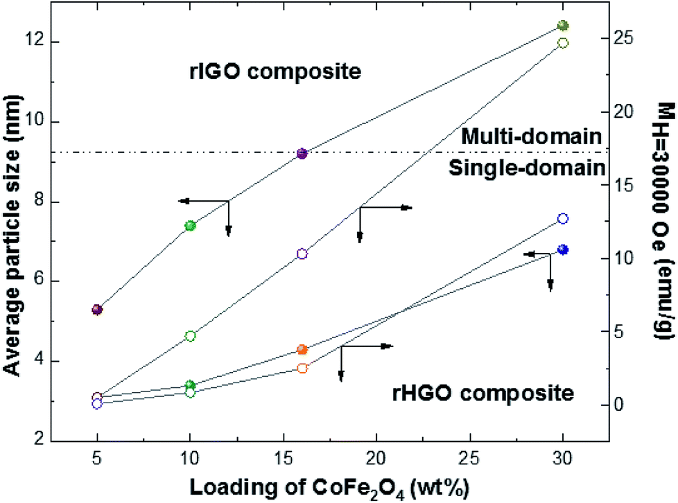 | ||
| Fig. 7 Plot correlating the CoFe2O4 loading with the average particle size and respective magnetization at 30000 Oe for the two rGOs studied. | ||
4.3 Magnetic resonance imaging
Superparamagnetic and ferromagnetic particles have been reported to similarly influence MRI contrast enhancement.38 Given the aforementioned observations (where both responses were observed), the T2-weighted magnetic resonance (MR) signal intensity of the standalone NPs and the two sets of composites were analysed. Different concentrations (0.0 to 0.2 mM) of these samples in agarose gel were studied at room temperature. The T2-weighted images in Fig. 8 clearly show that the MRI signal intensity is related to the concentration of iron, irrespective of the type of sample (darker images correspond to a decrease in the T2-weighted MR signal intensity). However, the contrast enhancement effect is particularly strong for the composites. Given the previously established correlation between the loading and average size of NPs, it is clear that the MR signal is dependent on the size of the NPs in the CoFe2O4–rGO composites.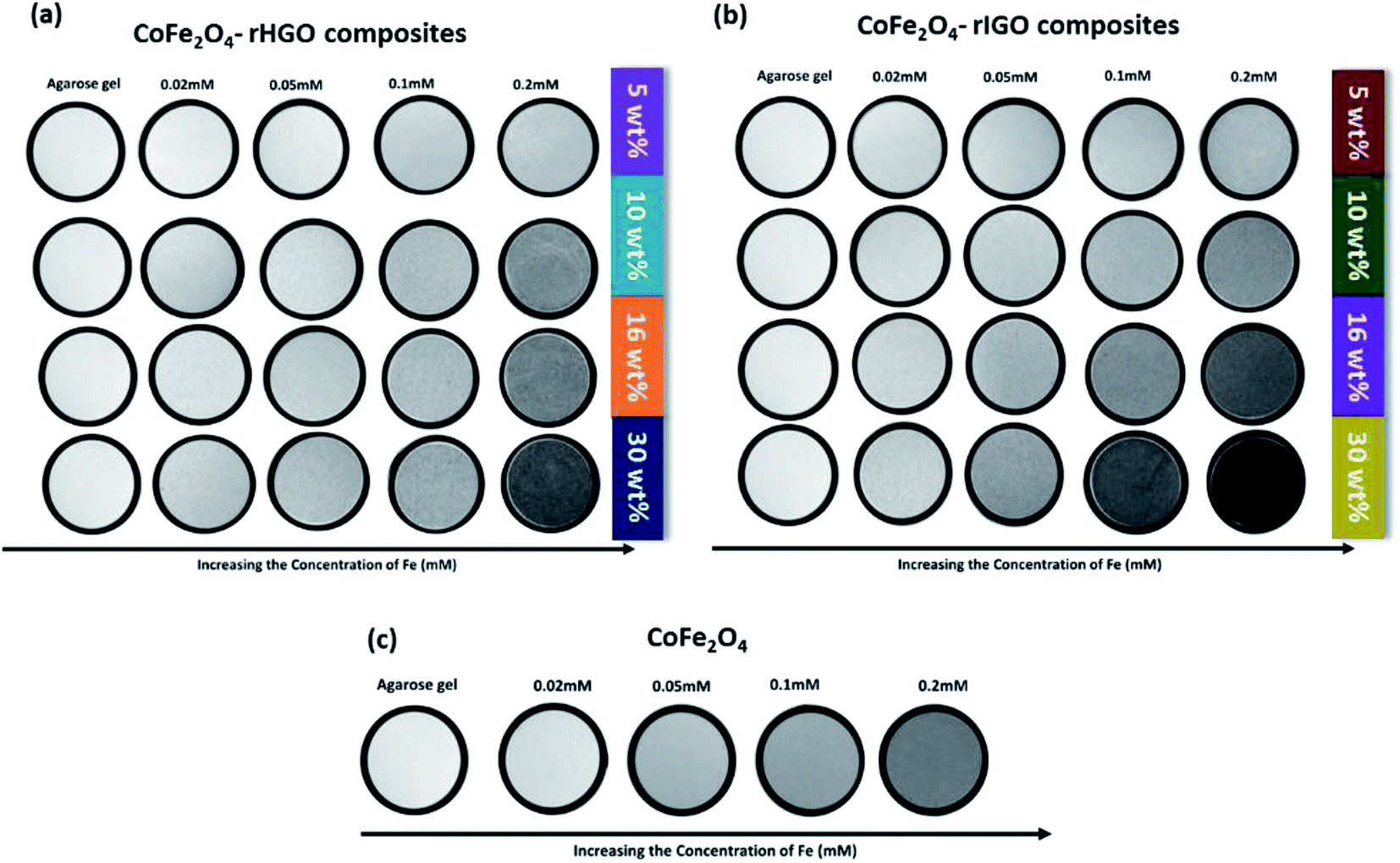 | ||
| Fig. 8 T2-weighted MRI images for: (a) CoFe2O4–rHGO composites, (b) CoFe2O4–rIGO composites and (c) pure CoFe2O4, at different Fe concentrations. | ||
Proton relaxivity (r2) values were obtained from the slope of the line fitted to the 1/T2 versus Fe concentration plot (Fig. 9). The r2 value of the standalone CoFe2O4 NPs was 112.4 mM−1 S−1. For the CoFe2O4–rHGO composites, the r2 values were 8.8 mM−1 S−1 (5 wt% CoFe2O4 loading), 16.7 mM−1 S−1 (10 wt%), 33.7 mM−1 S−1 (16 wt%) and 55.6 mM−1 S−1 (30 wt%). The r2 values of the CoFe2O4–rIGO composites were 17.4 mM−1 S−1 (5 wt%), 21.4 mM−1 S−1 (10 wt%), 43.6 mM−1 S−1 (16 wt%) and 102.1 mM−1 S−1 (30 wt%). The rIGO composites consistently showed higher r2 values than the corresponding rHGO composites. These results demonstrate that the r2 values depend not only on the CoFe2O4 loading but also on the type of GO precursor selected. Remarkably, the r2 of the 30 wt% CoFe2O4–rIGO composite is almost that of the standalone NPs. This result indicates that similar MRI contrast enhancement can be obtained despite the lower mass of ferrite present in the composite (1.7 mmole for the standalone CoFe2O4 against 0.55 mmole used to make the 30 wt% CoFe2O4–rIGO composite). Also of note, this r2 value is comparable to those of Fe-based commercial contrast agents such as Feridex® and Resovist® (see Table SI4† for a literature comparison of proton relaxivity values and corresponding particle sizes). Finally, to ensure that the composites had a negative T2-type of response, the 1/T1 values were plotted as a function of different concentrations of Fe (Fig. SI6†). Irrespective of considering the standalone or the composite samples, the r1 relaxivity is negligible (and practically constant) when compared to r2.
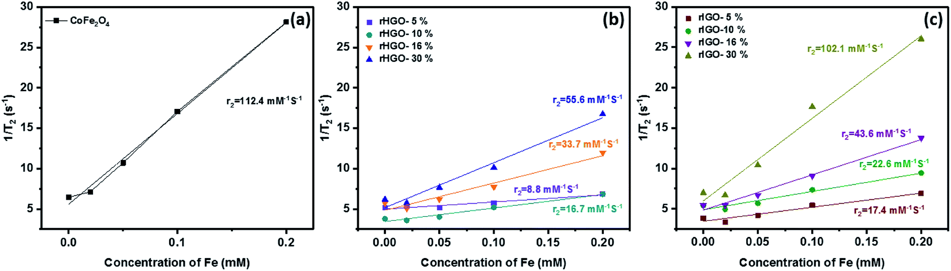 | ||
| Fig. 9 Plot of the T2 relaxation rate r2(1/T2) for: (a) pure CoFe2O4, (b) CoFe2O4–rHGO composites and (c) CoFe2O4–rIGO composites, suspended in aqueous solution at different Fe concentrations. | ||
Because loading and particle size are related in the CoFe2O4–rGO composites, a plot was constructed to show how the r2 values differ with size of the NPs (Fig. 10a). For both sets, a direct correlation is observed (i.e., r2 increases with increasing particle size), which corroborates previous claims.39,40 This size dependence is speculated to originate from surface spin anisotropy, a phenomenon that is more pronounced for smaller particles (due to the larger surface-area-to-volume ratios).41 Comparing the saturation magnetization (Ms) results obtained from the field-dependent magnetization measurements with the r2 values of the composites is also informative. Similar to previously reported behaviours,42 higher Ms values lead to more pronounced proton relaxivity (Fig. 10b). Taken together, the r2 is related to the Ms which, in turn, is affected by the size of the CoFe2O4 particles (that grow larger in the rIGO). The optimization of proton relaxivity (r2) is therefore also a function of the GO precursor.
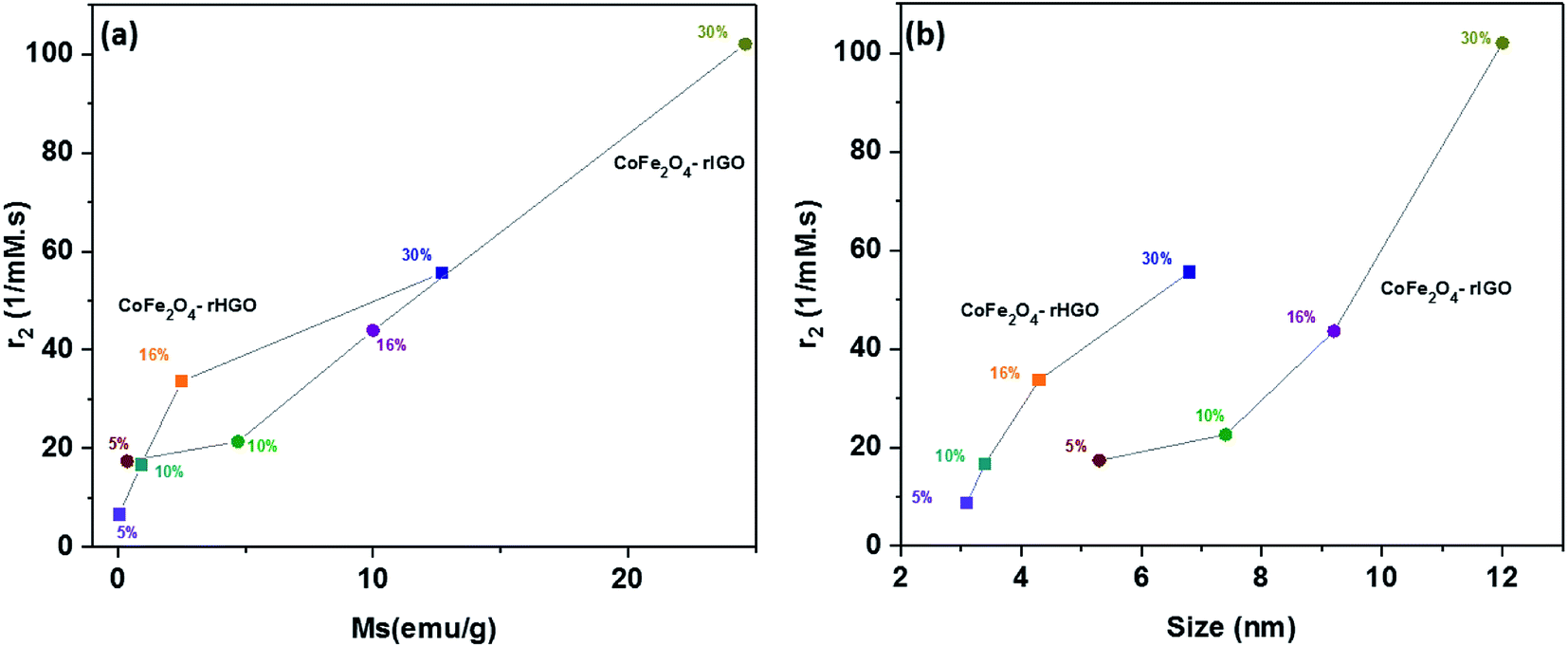 | ||
| Fig. 10 (a) Plot of the relaxivity coefficient r2 vs. Ms, i.e., magnetic saturation. (b) Plot of the relaxivity coefficient vs. magnetic nanostructure size. | ||
4.4 In vitro cytotoxicity
It is known that surface charge and the aggregation state of nanomaterials critically influence their in vitro cytotoxicity. Prior to the cell viability studies, the integrity of the composite materials in solution was tested. As shown in Table SI5,† the zeta (ζ)-potentials of the 30 wt% CoFe2O4–rHGO and 30 wt% CoFe2O4–rIGO composites were negative, with absolute values ranging from 30–40 mV. These figures imply a moderate to good stability of the dispersions, the rIGO composites having a slightly better dispersion degree. As per the high-resolution O1s XPS peak analysis (Fig. SI2†), this may be explained by the higher content of oxygen in the rIGO sample when compared to the rHGO one. Also from Table SI5,† note that the samples maintain similar ζ-potentials in aqueous phosphate buffered saline (PBS) for 24 h. To further estimate the aging behavior of these two composites in a PBS solution, visual inspection of settling over 24 h, and at room temperature, was carried out. At a concentration of 70 μg mL−1, the two samples showed excellent colloidal dispersity and stability (Fig. SI7†). We attribute this to their highly negative surface charge (electrostatic stabilization), which is consistent with the ζ-potentials measurements (Table SI5†). Adding to this, the microscopical inspection of the composites, after 24 h in the physiologic solution, did not reveal noticeable changes to the materials from their initial state (Fig. SI8†).Safety and toxicity are major concerns when considering the deployment of new MRI contrast agents. To evaluate the in vitro cytotoxicity of the rGOs and their composites with the highest CoFe2O4 loading (30 wt%), the viability of cells exposed to these materials was investigated using CCK-8 assays on HeLa cell lines. As shown in Fig. 11a, increasing the rGO concentration resulted in an overall decrease of cell viability. However, no statistically meaningful difference was observed between the two types of rGO used. Similar observations were made for the composite samples (Fig. 11b). It is noteworthy that the CoFe2O4–rGO composites showed 80% cell viability at a concentration of 50 μg mL−1. This corroborates the low cytotoxicity expected for these hybrid systems.
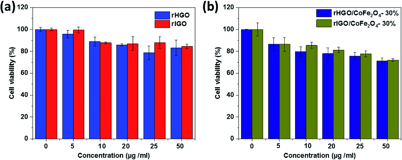 | ||
| Fig. 11 Viability of HeLa cells in different concentrations of: (a) rHGO/rIGO and (b) CoFe2O4–rHGO/CoFe2O4–rIGO. | ||
5. Conclusions
CoFe2O4–rGO composites were prepared to enhance the contrast and proton relaxivity coefficient for MRI. The effect of using different GO precursors bearing various concentrations of CoFe2O4 was studied. The type of GO and the loading of ferrite NPs play significant roles in tailoring the average particle size and magnetic properties of the composites. The 30 wt% CoFe2O4–rIGO sample showed the highest proton relaxivity value (102.1 mM−1 S−1) amongst all of the investigated composites. In fact, some of the properties measured were similar in magnitude and manner to those of the standalone NPs despite the smaller mass of CoFe2O4 present in the composites.Conflicts of interest
There are no conflicts of interest to declare.Acknowledgements
We are thankful for the financial support from KAUST (BAS/1/1346-01-01 and URF/1/3001-01-01). The technical support from the Core Labs at KAUST is appreciated. The TOC figure was created by Heno Hwang, scientific illustrator at KAUST.References
- A. G. Kolhatkar, A. C. Jamison, D. Litvinov, R. C. Willson and T. R. Lee, Tuning the magnetic properties of nanoparticles, Int. J. Mol. Sci., 2013, 14(8), 15977–16009 CrossRef PubMed.
- C. Sun, J. S. H. Lee and M. Zhang, Magnetic nanoparticles in MR imaging and drug delivery, Adv. Drug Delivery Rev., 2008, 60(11), 1252–1265 CrossRef CAS PubMed.
- A. H. Lu, E. e. L. Salabas and F. Schüth, Magnetic nanoparticles: synthesis, protection, functionalization, and application, Angew. Chem., Int. Ed., 2007, 46(8), 1222–1244 CrossRef CAS PubMed.
- V. Georgiadou, C. Kokotidou, B. Le Droumaguet, B. Carbonnier, T. Choli-Papadopoulou and C. Dendrinou-Samara, Oleylamine as a beneficial agent for the synthesis of CoFe2O4 nanoparticles with potential biomedical uses, Dalton Trans., 2014, 43(17), 6377–6388 RSC.
- K.-H. Choi, K. C. Nam, L. Malkinski, E. H. Choi, J.-S. Jung and B. J. Park, Size-Dependent Photodynamic Anticancer Activity of Biocompatible Multifunctional Magnetic Submicron Particles in Prostate Cancer Cells, Molecules, 2016, 21(9), 1187 CrossRef PubMed.
- S. Amiri and H. Shokrollahi, The role of cobalt ferrite magnetic nanoparticles in medical science, Mater. Sci. Eng., C, 2013, 33(1), 1–8 CrossRef CAS PubMed.
- E. Mendonça, M. A. Tenório, S. Mecena, B. Zucolotto, L. Silva, C. Jesus, C. Meneses and J. Duque, Intrinsic dependence of the magnetic properties of CoFe2O4 nanoparticles prepared via chemical methods with addition of chelating agents, J. Magn. Magn. Mater., 2015, 395, 345–349 CrossRef.
- G. Wang, Y. Ma, Z. Wei and M. Qi, Development of multifunctional cobalt ferrite/graphene oxide nanocomposites for magnetic resonance imaging and controlled drug delivery, Chem. Eng. J., 2016, 289, 150–160 CrossRef CAS.
- N. Venkatesha, R. Ashwini, P. Poojar, S. Geethanath and C. Srivastava, High Value of Proton Relaxivity Achieved by Graphene Oxide-Cobalt Ferrite Nanoparticle Composite: A Potential Contrast Agent in Magnetic Resonance Imaging, J. Indian Inst. Sci., 2014, 94(4), 415–422 Search PubMed.
- N. A. Kumar, H.-J. Choi, Y. R. Shin, D. W. Chang, L. Dai and J.-B. Baek, Polyaniline-grafted reduced graphene oxide for efficient electrochemical supercapacitors, ACS Nano, 2012, 6(2), 1715–1723 CrossRef CAS PubMed.
- D. C. Marcano, D. V. Kosynkin, J. M. Berlin, A. Sinitskii, Z. Sun, A. Slesarev, L. B. Alemany, W. Lu and J. M. Tour, Improved Synthesis of Graphene Oxide, ACS Nano, 2010, 4(8), 4806–4814 CrossRef CAS PubMed.
- S. Rasul, A. Alazmi, K. Jaouen, M. N. Hedhili and P. Costa, Rational design of reduced graphene oxide for superior performance of supercapacitor electrodes, Carbon, 2017, 111, 774–781 CrossRef CAS.
- A. Alazmi, O. El Tall, M. N. Hedhili and P. M. Costa, The impact of surface chemistry and texture on the CO2 uptake capacity of graphene oxide, Inorg. Chim. Acta, 2018, 482, 470–477 CrossRef CAS.
- M. Y. Rafique, L. Pan, M. Z. Iqbal and L. Yang, Influence of NaBH4 on the size, composition, and magnetic properties of CoFe2O4 nanoparticles synthesized by hydrothermal method, J. Nanopart. Res., 2012, 14(10), 1189 CrossRef.
- A. Alazmi, S. Rasul, S. P. Patole and P. M. Costa, Comparative study of synthesis and reduction methods for graphene oxide, Polyhedron, 2016, 116, 153–161 CrossRef CAS.
- A. Alazmi, O. El Tall, S. Rasul, M. N. Hedhili, S. P. Patole and P. M. Costa, A process to enhance the specific surface area and capacitance of hydrothermally reduced graphene oxide, Nanoscale, 2016, 8(41), 17782–17787 RSC.
- P. R. Kumar, P. Kollu, C. Santhosh, K. Eswara Varaprasada Rao, D. K. Kim and A. N. Grace, Enhanced properties of porous CoFe2O4-reduced graphene oxide composites with alginate binders for Li-ion battery applications, New J. Chem., 2014, 38(8), 3654–3661 RSC.
- Z. Wang, X. Zhang, Y. Li, Z. Liu and Z. Hao, Synthesis of graphene–NiFe2O4 nanocomposites and their electrochemical capacitive behavior, J. Mater. Chem. A, 2013, 1(21), 6393 RSC.
- P. He, K. Yang, W. Wang, F. Dong, L. Du and Y. Deng, Reduced graphene oxide-CoFe2O4 composites for supercapacitor electrode, Russ. J. Electrochem., 2013, 49(4), 359–364 CrossRef CAS.
- X. Lu, L. Yang, X. Bian, D. Chao and C. Wang, Rapid, Microwave-Assisted, and One-Pot Synthesis of Magnetic Palladium–CoFe2O4–Graphene Composite Nanosheets and Their Applications as Recyclable Catalysts, Part. Part. Syst. Charact., 2014, 31(2), 245–251 CrossRef CAS.
- Z. Song, W. Ran and F. Wei, One-step approach for the synthesis of CoFe2O4@ rGO core-shell nanocomposites as efficient adsorbent for removal of organic pollutants, Water Sci. Technol., 2017, 75(2), 397–405 CrossRef CAS PubMed.
- R. D. Waldron, Infrared Spectra of Ferrites, Phys. Rev., 1955, 99(6), 1727–1735 CrossRef CAS.
- M. Naebe, J. Wang, A. Amini, H. Khayyam, N. Hameed, L. H. Li, Y. Chen and B. Fox, Mechanical Property and Structure of Covalent Functionalised Graphene/Epoxy Nanocomposites, Sci. Rep., 2014, 4, 4375 CrossRef PubMed.
- Z. Ji, X. Shen, Y. Song and G. Zhu, In situ synthesis of graphene/cobalt nanocomposites and their magnetic properties, Mater. Sci. Eng., B, 2011, 176(9), 711–715 CrossRef CAS.
- Y. Xu, H. Bai, G. Lu, C. Li and G. Shi, Flexible Graphene Films via the Filtration of Water-Soluble Noncovalent Functionalized Graphene Sheets, J. Am. Chem. Soc., 2008, 130(18), 5856–5857 CrossRef CAS PubMed.
- C. Galande, A. D. Mohite, A. V. Naumov, W. Gao, L. Ci, A. Ajayan, H. Gao, A. Srivastava, R. B. Weisman and P. M. Ajayan, Quasi-Molecular Fluorescence from Graphene Oxide, Sci. Rep., 2011, 1, 85 CrossRef PubMed.
- B. Shatabda, M. Ramaprasad, S. Moni Baskey, S. Shyamal Kumar and C. Dipankar, Anomalous enhancement in the magnetoconductance of graphene/CoFe 2 O 4 composite due to spin–orbit coupling, J. Phys. D: Appl. Phys., 2015, 48(43), 435002 CrossRef.
- S. Park, K.-S. Lee, G. Bozoklu, W. Cai, S. T. Nguyen and R. S. Ruoff, Graphene Oxide Papers Modified by Divalent Ions—Enhancing Mechanical Properties via Chemical Cross-Linking, ACS Nano, 2008, 2(3), 572–578 CrossRef CAS PubMed.
- S. Chen, J. Zhu, X. Wu, Q. Han and X. Wang, Graphene Oxide−MnO2 Nanocomposites for Supercapacitors, ACS Nano, 2010, 4(5), 2822–2830 CrossRef CAS PubMed.
- C. Xu, X. Wang, J. Zhu, X. Yang and L. Lu, Deposition of Co3O4nanoparticles onto exfoliated graphite oxide sheets, J. Mater. Chem., 2008, 18(46), 5625–5629 RSC.
- J. M. D. Coey, Noncollinear spin arrangement in ultrafine ferrimagnetic crystallites, Phys. Rev. Lett., 1971, 27(17), 1140 CrossRef CAS.
- B. Martinez, A. Roig, X. Obradors, E. Molins, A. Rouanet and C. Monty, Magnetic properties of γ-Fe2O3 nanoparticles obtained by vaporization condensation in a solar furnace, J. Appl. Phys., 1996, 79(5), 2580–2586 CrossRef CAS.
- J. Chen, C. Sorensen, K. Klabunde, G. Hadjipanayis, E. Devlin and A. Kostikas, Size-dependent magnetic properties of MnFe2O4 fine particles synthesized by coprecipitation, Phys. Rev. B: Condens. Matter Mater. Phys., 1996, 54(13), 9288 CrossRef CAS.
- K. V. Shafi, A. Gedanken, R. Prozorov and J. Balogh, Sonochemical preparation and size-dependent properties of nanostructured CoFe2O4 particles, Chem. Mater., 1998, 10(11), 3445–3450 CrossRef CAS.
- A. Morr and K. Haneda, Magnetic structure of small NiFe2O4 particles, J. Appl. Phys., 1981, 52(3), 2496–2498 CrossRef.
- H. M. Joshi, Y. P. Lin, M. Aslam, P. V. Prasad, E. A. Schultz-Sikma, R. Edelman, T. Meade and V. P. Dravid, Effects of Shape and Size of Cobalt Ferrite Nanostructures on Their MRI Contrast and Thermal Activation, J. Phys. Chem. C, 2009, 113(41), 17761–17767 CrossRef CAS PubMed.
- M. Colombo, S. Carregal-Romero, M. F. Casula, L. Gutiérrez, M. P. Morales, I. B. Böhm, J. T. Heverhagen, D. Prosperi and W. J. Parak, Biological applications of magnetic nanoparticles, Chem. Soc. Rev., 2012, 41(11), 4306–4334 RSC.
- C. Rümenapp, B. Gleich and A. Haase, Magnetic Nanoparticles in Magnetic Resonance Imaging and Diagnostics, Pharm. Res., 2012, 29(5), 1165–1179 CrossRef PubMed.
- H. M. Joshi, Y. P. Lin, M. Aslam, P. Prasad, E. A. Schultz-Sikma, R. Edelman, T. Meade and V. P. Dravid, Effects of shape and size of cobalt ferrite nanostructures on their MRI contrast and thermal activation, J. Phys. Chem. C, 2009, 113(41), 17761–17767 CrossRef CAS PubMed.
- Y.-w. Jun, Y.-M. Huh, J.-s. Choi, J.-H. Lee, H.-T. Song, K. Kim, S. Yoon, K.-S. Kim, J.-S. Shin, J.-S. Suh and J. Cheon, Nanoscale Size Effect of Magnetic Nanocrystals and Their Utilization for Cancer Diagnosis via Magnetic Resonance Imaging, J. Am. Chem. Soc., 2005, 127(16), 5732–5733 CrossRef CAS PubMed.
- F. Liu, S. Laurent, A. Roch, L. V. Elst and R. N. Muller, Size-controlled synthesis of CoFe2O4 nanoparticles potential contrast agent for MRI and investigation on their size-dependent magnetic properties, J. Nanomater., 2013, 2013, 127 Search PubMed.
- Y.-w. Jun, J.-w. Seo and J. Cheon, Nanoscaling Laws of Magnetic Nanoparticles and Their Applicabilities in Biomedical Sciences, Acc. Chem. Res., 2008, 41(2), 179–189 CrossRef CAS PubMed.
Footnote |
| † Electronic supplementary information (ESI) available. See DOI: 10.1039/c8ra09476d |
| This journal is © The Royal Society of Chemistry 2019 |