
 Open Access Article
 This Open Access Article is licensed under a Creative Commons Attribution-Non Commercial 3.0 Unported Licence
The synthesis of hierarchical high-silica beta zeolites in NaF media†
Guang Xiong *,
Miaomiao Feng,
Jiaxu Liu,
Qingrun Meng,
Liping Liu and
Hongchen Guo
*,
Miaomiao Feng,
Jiaxu Liu,
Qingrun Meng,
Liping Liu and
Hongchen Guo
State Key Laboratory of Fine Chemicals, School of Chemical Engineering, Dalian University of Technology, Dalian, 116024, China. E-mail: gxiong@dlut.edu.cn; Fax: +86-411-84986340
First published on 28th January 2019
Abstract
An aerosol-assisted hydrothermal method has been applied to synthesizing hierarchical beta zeolites with SiO2/Al2O3 ratios ranging from 44 to 392 in NaF media. Two different morphologies, including nano-aggregates with interparticle mesopores and plate-like zeolites with intracrystalline mesopores, can be formed depending on the SiO2/Al2O3 ratios of the synthesis gels. A possible mechanism for the formation of the beta zeolites has been proposed. The obtained beta zeolites show hierarchical pores, good Al species distribution and less internal defect sites. Evaluation, by the cracking of 1,3,5-triisopropylbenzene (1,3,5-TIPB), is consistent with the acidic properties and the pore structure of beta zeolites with different ratios of SiO2/Al2O3.
Introduction
A beta zeolite is a large-pore material with a three-dimensional structure of 12-membered ring channels.1 It has been used in the petrochemical industry, and in fine chemistry and adsorption,2,3 owing to its large pore size, strong acid sites and high chemical and thermal stability. In particular, synthesis of the high-silica beta zeolite has drawn significant attention owing to its unique acid density, large pore size and high hydrophobicity. A high-silica beta zeolite with a low acid density exhibited a superior performance in methanol for the olefin (MTO) reaction, providing good product selectivity and a long catalytic lifetime.4–6 In addition, high-silica beta zeolites exhibited a lower deactivation rate for the methylation of phenol owing to their suitable acidity.7 Moreover, the high-silica beta zeolite also exhibited a high isosorbide yield in the dehydration of sorbitol in water,8 and an excellent ability for large-sized volatile organic compound (VOC) adsorption owing to the high hydrophobicity.9Beta zeolites with Si/Al ratios from 5 to 100 can be synthesized through crystallization of mixtures including aluminosilicate sol–gel solution and tetraethylammonium hydroxide (TEA) in alkaline media.10 However, the synthesis of high-silica beta zeolites (Si/Al > 100) is relatively difficult. In alkaline systems, a pure silica beta has been synthesized using 4,4′-trimethylenebis (TMP) and other quaternary ammonium cations.11,12 In most cases deboronated or dealuminated beta zeolites are used as seeds.13,14 Pure silica beta can be synthesized in near-neutral media containing the template TEAOH and the mineralization agent HF.10 The same method has been applied to the synthesis of heteroatom BEA zeolites such as Sn, Ti, Mn-beta.15–19 Both the fluoride and the hydroxide anion can be used as the mineralizer.20,21 However, there are clear distinctions between the zeolites produced in fluoride and hydroxide synthesis systems.22,23 In a hydroxide media, a lot of internal defect sites are formed in the silica beta zeolite, which result in their hydrophilicity properties.9,24 However, beta zeolites synthesized in a fluoride system are highly hydrophobic owing to the lack of structural defects.
The use of the fluorine sources such as HF and NH4F, leads to a long crystallization time and large crystal sizes.15,25 Large-sized beta zeolites with a microporous structure hinder the approachability of the active sites by the large-sized reactant. Therefore, it would be significant to synthesize a high-silica zeolite beta that possessed hierarchical pores to improve diffusivity,26 and hence increase the reaction rate and catalytic lifetime.27 Recently, Wang et al. used alkaline and fluorine-containing salts as mineralization agents to synthesize a framework defect-free beta zeolite.28 It was found that the addition of NaF was important to decreasing the crystal size.
Many other methods have been reported to synthesize hierarchical beta zeolites, such as hard-templating,29 soft-templating,30 and post treatment methods.31 However, it is still desirable to synthesize a hierarchical beta zeolite using a simple and economic method without the need for a secondary template.
The aerosol process is an industrial method that is used to synthesize various types of mesoporous and macroporous materials.32 In previous reports, the aerosol-assisted method has been applied to the synthesis of various microporous materials including TS-1, ZSM-5 and beta zeolites.33–36 Using this method the amount of template and the crystallization time are reduced. The zeolites synthesized using the aerosol-assisted method exhibit good catalytic performances. The aim of this study is to synthesize a high-silica beta zeolite with hierarchical pores using the aerosol-assisted hydrothermal method in NaF media. The optimal synthesis conditions were determined and the synthetic mechanism was investigated. Finally, the acid sites and pore structure of the obtained beta zeolites were investigated using a probe reaction, the cracking of 1,3,5-TIPB.
Experimental
Materials
The raw materials were: NaAlO2 (41.0 wt% Al2O3, Sinopharm Chemical Reagent Co. Ltd), colloidal silica (30 wt% SiO2, Qingdao Cheng Yu Chemical Co., Ltd), sodium fluoride (NaF ≥ 98%, Tianjin Fuchen Chemical Reagents Co. Ltd), tetraethylammonium hydroxide (25 wt% TEAOH, Tianjin Guangfu Fine Chemical Research Institute), and H-beta zeolite (SiO2/Al2O3 = 30, Qiwangda Chemical Technology CO. Ltd, Dalian).Synthesis
Typically, the synthesis of the beta zeolite using aerosol-assisted hydrothermal synthesis was performed as follows: NaAlO2 and colloidal silica were dissolved in deionized water. The final solution composition was SiO2![[thin space (1/6-em)]](https://www.rsc.org/images/entities/char_2009.gif) :0–0.02Al2O3:0–0.02Na2O:25H2O. The aerosol particles were generated via an aerosol generator (NAI-GZJ, Shanghai Naai Instrument Co., Ltd.) at 230 °C.
:0–0.02Al2O3:0–0.02Na2O:25H2O. The aerosol particles were generated via an aerosol generator (NAI-GZJ, Shanghai Naai Instrument Co., Ltd.) at 230 °C.
The SiO2–Al2O3–Na2O amorphous powder was dried at 110 °C, and then mixed with sodium fluoride and tetraethylammonium hydroxide (25%, TEAOH). In some cases 5 wt% beta seeds (SiO2/Al2O3 = 30) were required. The mixture, which had a molar ratio of 1SiO2:0–0.02Al2O3:0–0.02Na2O:0.15–0.2NaF:0.15–0.2 TEAOH:3.68–4.91H2O was loaded into a Teflon-lined autoclave, aged at 120 °C for 24 h, and then crystallized at 150 °C for 24–96 h under autogenous pressure. The product was collected by filtration, washing, and drying at 100 °C and calcined at 540 °C for 10 hours. The H-form beta zeolite was obtained by stirring the calcined zeolite into 1 M NH4NO3 solution at 80 °C for 2 h, twice. Finally, the zeolites were calcined at 540 °C for 6 hours.
All samples were expressed as Bx, x indicates the SiO2/Al2O3 ratio of the initial compound. The sample BS-1/2 represented the zeolite synthesized from Ludox. The relative crystallinity was calculated by comparing the intensity of the peak (2θ = 22.4) of the Bx samples with that of the B50 sample.
Characterization
Rigaku D/MAX-2400 apparatus was operated at a scanning rate of 8° min−1 to obtain the X-ray diffraction (XRD) patterns between the range of 2θ = 5–50° with CuKα radiation. The scanning electron microscopy (SEM) images were determined using a FEI Nova NanoSEM450. Transmission electron microscopy (TEM) images were obtained on a FEI Tecnai F30 instrument at 300 kV. A Nicolet is10 Fourier-transform infrared (FT-IR) spectrometer was used to characterize the hydroxyl vibrations between 4000–3200 cm−1. Inductively coupled plasma (ICP) spectroscopy was used for the elemental analysis in Optima 2000 DV. Quantachrome AUTOSORB-1 apparatus was used to measure the nitrogen sorption isotherms at 77 K. The Brunauer–Emmett–Teller (BET), t-plot and Barrett, Joyner, and Halenda (BJH) methods were used to calculate and analyse the surface area and pore volume, respectively. To analyse the acidic strength distributions and total acidity of the catalysts, a Quantachrome CHEMBET-3000 instrument was used to obtain the NH3-TPD profiles in He flow at a rate of 10 min−1 to 650 °C. An Agilent DD2-500 MHz spectrometer was applied to record the 27Al and 29Si MAS NMR spectra using a spinning speed of 14 and 13 kHz, respectively. The chemical shifts were referenced to 1% Al(NO3)3 and tetramethylsilane aqueous solution, respectively.Catalytic test
The 1,3,5-TIPB cracking reaction was used to investigate the pore structure and acidity of the beta zeolites. The catalyst, 0.1 g, (20–40 mesh) was added to the stainless U-tube reactor and activated with nitrogen at 400 °C for 3 h. Then, 0.3 μL 1,3,5-TIPB (95 wt%, Aladdin) was introduced into the reactor under a 0.1 MPa nitrogen flow. Online GC-7890T equipped with a thermal conductivity detector (TCD) was used to analyse the products. The temperatures of the chromatogram detector and the injection port were 270 °C. Data analysis was compared to the literature values.37Results and discussion
Optimal synthesis conditions for the beta zeolites
The synthesis conditions of the beta zeolites with various SiO2/Al2O3 ratios are displayed in Table 1. All samples were aged at 120 °C for 1 d to generate further crystal nuclei.35 It was observed that the beta zeolites can be obtained with a relatively low amount of mineralizer/template (NaF:SiO2 = 0.15, TEA:SiO2 = 0.15). After optimizing the crystallization temperature and time, the samples with an initial SiO2/Al2O3 ratio between 50–100 could be obtained without the use of seeds. When the initial ratios of SiO2/Al2O3 were increased further the addition of the seeds was necessary.
| Sample | NaF:SiO2 and TEAOH:SiO2 |
Seed/Si/wt% | Temperaturea/°C | Time/d | SiO2/Al2O3b | Relative crystallinity (%) | |
|---|---|---|---|---|---|---|---|
| Precursor | Products | ||||||
| a All samples are pre crystallized at 120 °C for 1 d.b Determined using ICP-AES. | |||||||
| B50 | 0.15 | — | 150 | 2 | 47 | 44 | 100 |
| B100 | 0.15 | — | 150 | 2 | 90 | 85 | 97 |
| B150 | 0.15 | 5 | 130 | 4 | 139 | 99 | 94 |
| B300 | 0.15 | 5 | 130 | 4 | 219 | 154 | 82 |
| BS-1 | 0.15 | 5 | 130 | 4 | 3052 | — | 70 |
| BS-2 | 0.2 | 5 | 130 | 4 | 3052 | 392 | 79 |
Table 1 shows the SiO2/Al2O3 ratios of the precursor and the BEA samples. It should be noted that the raw material (the silica gel 30%) contains an aluminium impurity (SiO2/Al2O3 = 3654). In the absence of the seeds, the SiO2/Al2O3 ratios of the BEA samples (B50-B100) are close to those of the raw materials. However, the addition of the seeds (SiO2/Al2O3 = 30) lead to a further decrease in the SiO2/Al2O3 ratios of the products. The effect of the SiO2/Al2O3 ratios of the seeds on the XRD patterns of the zeolites is exhibited in Fig. S1.† It can be seen that only the seeds with a SiO2/Al2O3 ratio = 30 are effective for the synthesis of the high-silica zeolite beta. The seeds with higher SiO2/Al2O3 ratios may dissolve too quickly under the highly alkaline conditions, and therefore are not very effective in this synthesis system. Therefore, the Al species can be introduced from the Al source (NaAlO2), the Si source (Ludox) or the seed.
The highest SiO2/Al2O3 ratio of 392 was achieved when Ludox and the seeds were used as the starting materials.
The XRD patterns of the BEA samples with different SiO2/Al2O3 ratios are exhibited in Fig. 1. Fig. 1a and b show diffraction peaks that are typical for BEA – type topology.1 This indicates that well-crystallized beta zeolites in a broad range of SiO2/Al2O3 ratios can be obtained by optimizing the synthesis conditions. For the BS samples, a higher crystallinity can be achieved if the template and mineralizer amounts are increase appropriately.
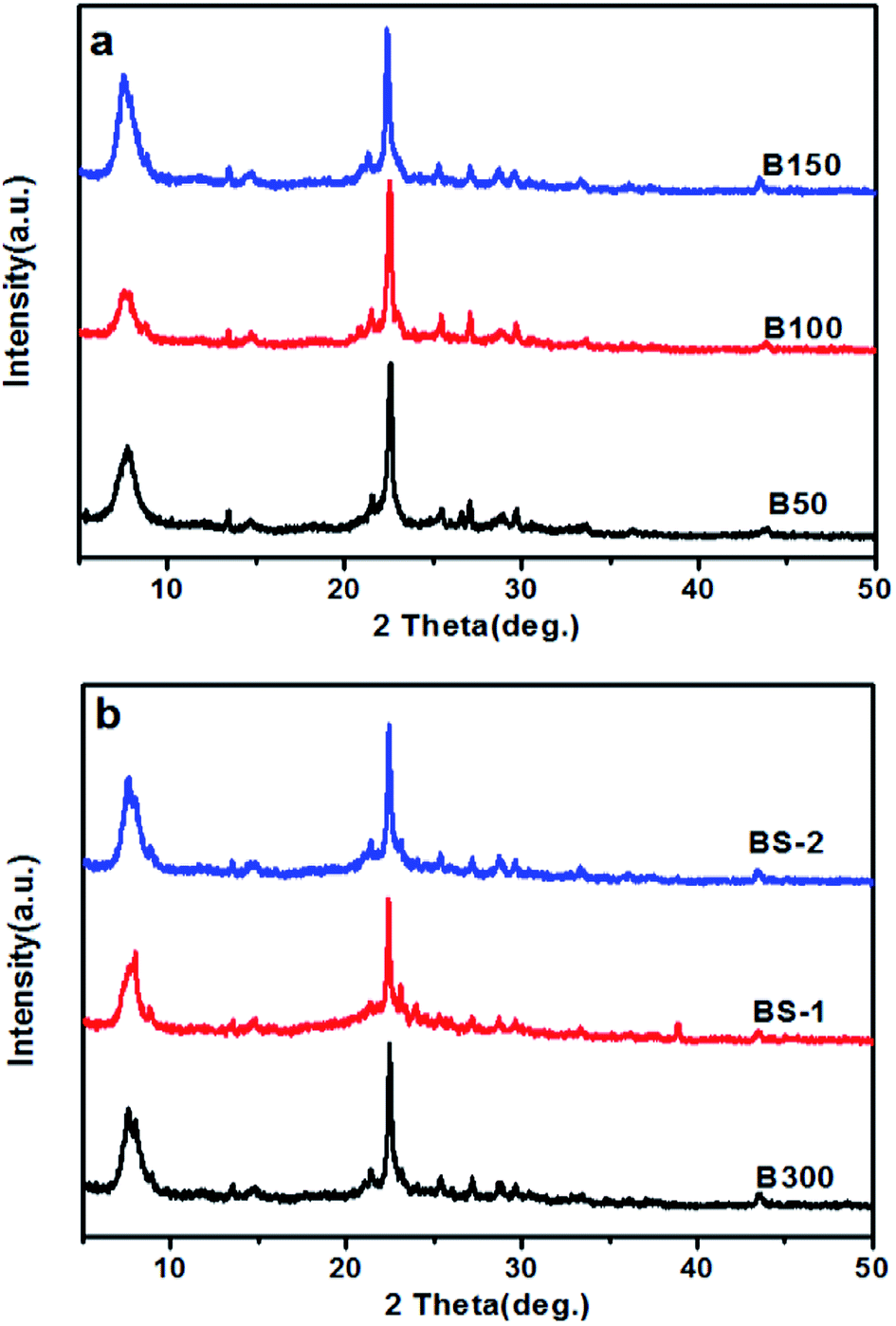 | ||
| Fig. 1 XRD patterns for: (a) the samples B50-B150; and (b) the samples B300-BS-2. | ||
Fig. 2 shows the SEM images of the BEA samples. The morphology of the B50 sample shows the spherical nano-aggregates. Upon increasing the SiO2/Al2O3 ratio to 150, the nanocrystal aggregates more tightly to form irregular particles with a larger size. However, when the SiO2/Al2O3 ratio is increased further, the particle sizes becomes smaller and more uniform. The BS-2 sample shows square plate-like aggregates with a size of 100 × 500 × 500 nm, which is much smaller than those of the pure silica beta synthesized at near neutral pH with HF as the mineralizer.10 This is because the crystallization occurred in a dense system with a high alkalinity, which facilitates the nucleation of the crystals and reduces the crystal size. The existence of Al species is beneficial to the formation of the crystal nucleus.11 Thus, the morphology changes from nanocrystal aggregates to plate-like crystals as the SiO2/Al2O3 ratio increases.
 | ||
| Fig. 2 SEM images of the BEA samples. | ||
Fig. 3 shows the N2 sorption isotherms of the BEA samples. All of the samples show a type IV isotherm, including a steep rise in the uptake at low pressure and a hysteresis loop at high pressure. This indicates the existence of micropores and mesopores, respectively.38 The hysteresis loop becomes more obvious with the increasing SiO2/Al2O3 ratio. As shown in Fig. 3b, the distribution of the pore sizes becomes wider as the SiO2/Al2O3 ratio increases. Table 2 lists the textural properties of the BEA samples. By increasing the SiO2/Al2O3 ratio, the BET surface area gradually decreases, and the external surface area first increases and then decreases. This could be attributed to changes in the morphology and aggregation. Meanwhile, the mesopore volume rises from 0.21 to 0.28 cm3 g−1 along with a decrease in the micropore volume from 0.23 to 0.09 cm3 g−1. It can be seen that the relative crystallinity of the BEA sample decreases with the increasing SiO2/Al2O3 ratio (Table 1). This may explain the decrease in the micropore volumes.
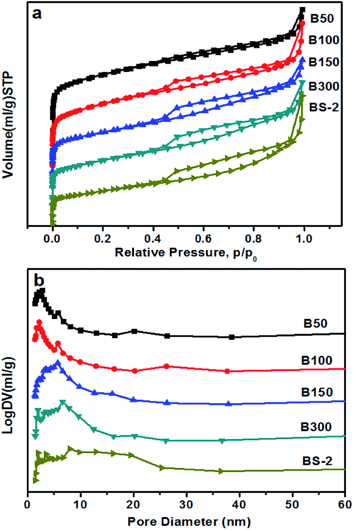 | ||
| Fig. 3 (a) N2 sorption isotherm, and (b) BJH pore size distribution of the BEA samples. | ||
| Sample | Surface area (m2 g−1) | Pore volume (cm3 g−1) | |||
|---|---|---|---|---|---|
| SBET | Smicro | Sext | Vmicro | Vmeso | |
| B50 | 585 | 460 | 125 | 0.23 | 0.21 |
| B100 | 539 | 408 | 131 | 0.21 | 0.24 |
| B150 | 460 | 294 | 166 | 0.15 | 0.25 |
| B300 | 447 | 295 | 152 | 0.15 | 0.26 |
| BS-2 | 296 | 183 | 113 | 0.09 | 0.28 |
The formation of the mesopore was confirmed using the TEM image shown in Fig. 4. As shown in Fig. S2,† after the crystallization at 130 °C for 48 h, the nano-sized crystals aggregate together. Therefore, the hierarchical structure should be formed by the aggregation of small crystals, thus generating the stacking interspace. The crystal edge shows the regular lattice fringes of the microporous zeolite, which corresponds to the smooth edge in the SEM image (Fig. 8).
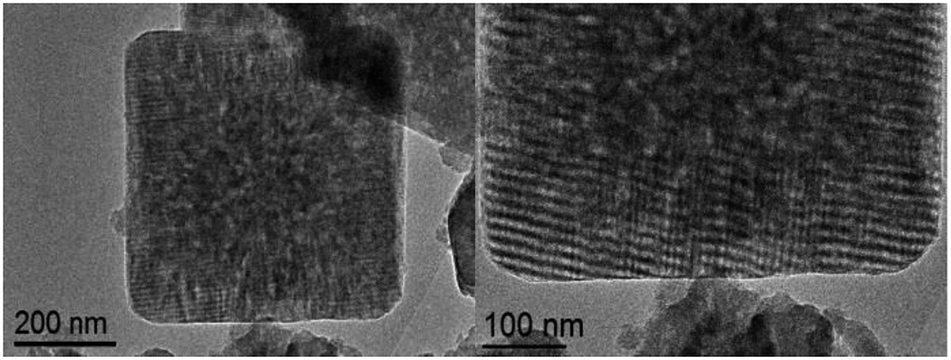 | ||
| Fig. 4 TEM images of the BS-2 sample. | ||
Fig. 5a shows the 29Si MAS NMR spectra of the BEA samples. The resonance positions of −113 and −116 ppm are associated with the (SiO)4Si groups (Q4). There are very weak signals at −105 ppm for the samples B50-300. It was reported that the signal at −95 to −105 ppm could be assigned to Si(OSi)3(OAl). However, a signal for Si(OSi)3(OH) could be observed at a similar position (−100 to −103 ppm),39 and thus cannot be excluded. As the SiO2/Al2O3 ratio further increases, the signal at −105 ppm can barely be observed. This indicates that the BEA samples with a high SiO2/Al2O3 ratio synthesized in NaF media exhibit few defects. The F− can balance the positive electricity of the structure directing agents and the charge of the Si–O−, which helps to reduce the amount of framework defects.40
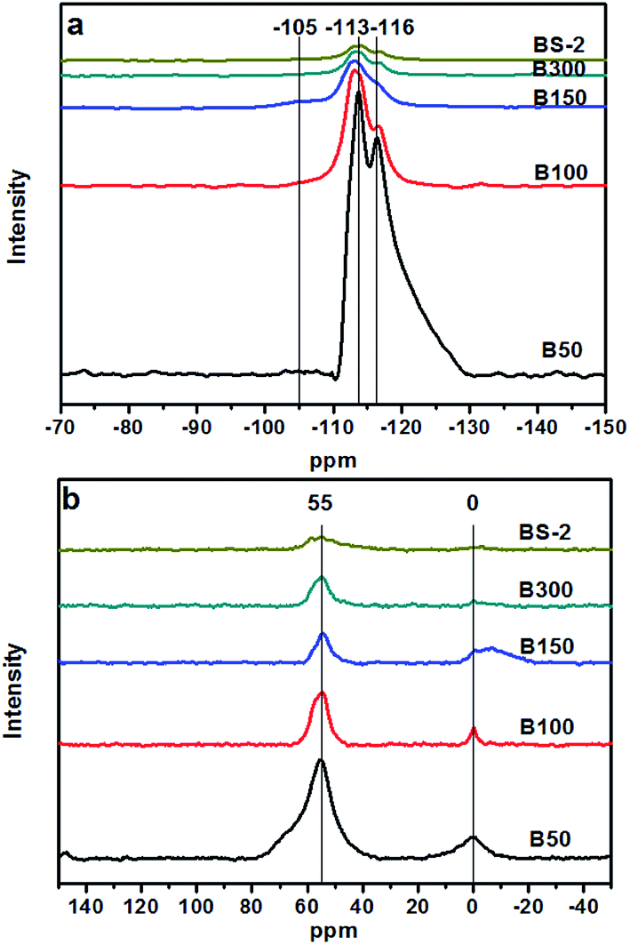 | ||
| Fig. 5 29Si (a) and 27Al MAS NMR spectra (b) of the BEA samples. | ||
Fig. 5b shows the 27Al MAS NMR spectra of the BEA samples. The resonance bands around 55 and 0 ppm are associated with the tetrahedrally coordinated framework Al species and the extra-framework Al species, respectively.41 Upon a decrease of the Al amount, the intensity of the signal around 55 ppm decreases gradually, indicating a decrease in the amount of the framework Al. The resonance band at 0 ppm is associated with the extra-framework Al species. With the decrease in the amount of Al, the overall trend of the peak intensity decreases gradually. However, compared to the B50 and B100 samples, the B150, B300, BS-2 samples were synthesized with seeds at a lower temperature to prolong the crystallization time. This may cause the generation of the extra-framework Al species in highly asymmetric or multinomial environment, which lead to the broad peak at 0 ppm.
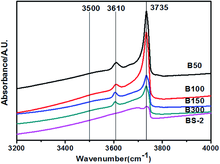
Fig. 6 shows the hydroxyl-IR spectra for the BEA samples. The samples exhibit bands at 3610 and 3735 cm−1 corresponding to the bridging hydroxyl groups (Si–OH–Al) and isolated Si–OH, respectively. The peak intensities decrease with the increasing SiO2/Al2O3 ratio. For the B50-300 samples, a very weak signal at 3500 cm−1 can be observed. The band is assigned to the hydrogen bonded silanol groups. Upon further increasing the SiO2/Al2O3 ratio, the band disappeared. This indicates that the BEA samples with a high SiO2/Al2O3 ratio synthesized in NaF media exhibit few internal defects.
 | ||
| Fig. 6 Hydroxyl-IR spectra for the BEA samples. | ||
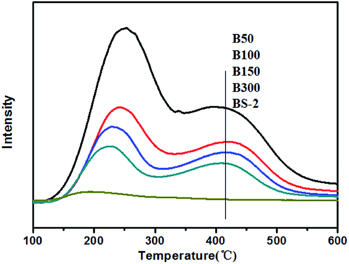
Fig. 7 displays the NH3-TPD results for the BEA samples. The B50-BS-2 samples exhibit desorption peaks at 380–450 °C and 220–250 °C, which are consistent with the strong and weak acid sites, respectively. In general, the Lewis acid site is the weak acid site. The Brønsted acid site corresponds to the strong acid site, which is associated with the framework aluminum atom.42,43
 | ||
| Fig. 7 NH3-TPD curves for the BEA samples. | ||
By increasing the aluminum amount, the amounts of the strong and weak acid sites increase gradually. Meanwhile, the desorption temperatures shift to the high-temperature side slightly, indicating that the acid strength becomes stronger.
Crystallization process for the beta zeolite
There have been many efforts to study the crystallization mechanisms, including using liquid,44 solid,25 and solid–liquid two phase transformations.45 To further understand the crystallization process of the high-silica BEA zeolite, the crystallization mechanism of the BS-2 sample was investigated using XRD and SEM techniques.The XRD patterns of the BEA zeolites obtained at different crystallization times are recorded in Fig. 8a. The crystallization curve is presented in Fig. 8b. The crystallization curve of BS-2 shows a typical S-type curve,46 including an induction period, the growth period and the growth ending period. The long induction period (0–24 h, 120 °C) is necessary for accumulating amorphous materials which have the short-range ordered structure.47 The weak peaks at 2θ = 7.8° and 22.4° for the BEA topology begin to appear from 24 h. During the growth period, the peak intensities increase rapidly, indicating that the amorphous phase is transformed into the framework of the BEA zeolite. The well-crystallized BEA samples can be obtained after the crystallization at 130 °C for 96–120 h. After that the relative crystallinity drops.
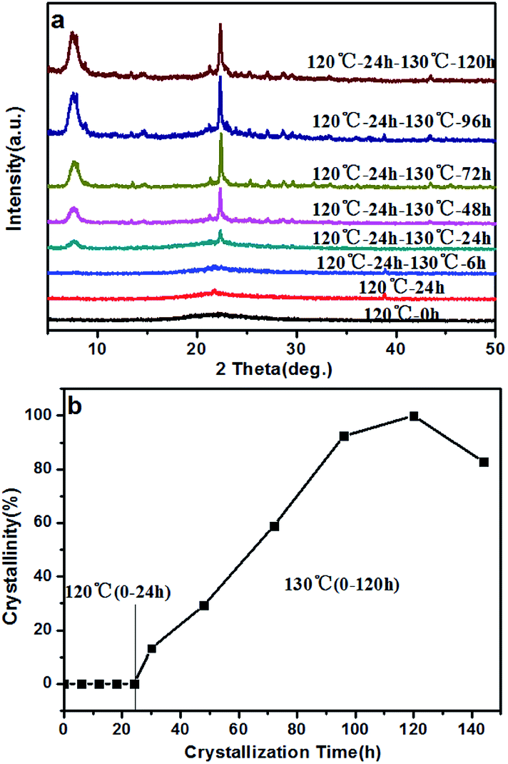 | ||
| Fig. 8 XRD patterns (a), and crystallization curve (b), for the BS-2 sample obtained at different periods of time. | ||
The morphology change of the BS-2 sample is exhibited in the SEM images (Fig. 9). At the beginning, the precursor (0 h) consists of irregular spherical particles surrounded by seeds. As the temperature rises, the precursor is aggregated and is gradually dissolved (120 °C, 6–24 h). After crystallization at 130 °C for 6 and 48 h, small crystals are generated. This manifests the initial formation of the Beta zeolite during the growth period, as confirmed using the XRD patterns. The precursor disappears rapidly after crystallization at 130 °C for 48 h. The square plate-like crystals are formed by the aggregation of small crystals. This explains the formation of the mesopore in the crystal and is in agreement with the results obtained using TEM. By further increasing crystallization time the amount of plate-like BEA crystals is significantly increased and the surface of the zeolite crystal becomes rough.
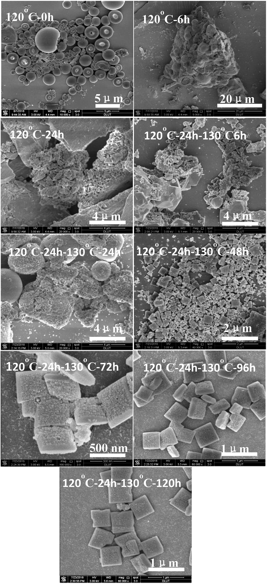 | ||
| Fig. 9 SEM images of the BS-2 sample obtained after different periods of time. | ||
When the crystallization was completed BEA crystals with a size of 100 × 500 × 500 nm were obtained.
In conclusion, the high-silica BEA zeolite with mesopores can be synthesized via the aerosol-assisted route in NaF media. The nucleation and growth of the BEA samples primarily occurs in the liquid phase.
Catalytic performance
The catalytic cracking of 1,3,5-TIPB was used as a probe reaction to evaluate the acidic properties and pore structure of the BEA samples with different SiO2/Al2O3 ratios. There are three successional dealkylation reactions during the cracking of 1,3,5-TIPB. These are: 1,3,5-TIPB: 1,3,5-triisopropylbenzene, MIPB: m-diisopropylbenzene, and Pro: propylene:37| TIPB → Pro + MIPB | (1) |
| MIPB → Pro + IPB | (2) |
| IPB → Pro + Ben | (3) |
There are some side reactions, including disproportionation, isomerization and condensation, that is the isomerization of MIPB forms the p-diisopropylbenzene (PIPB).48 Step 1 and 2 can proceed on relatively weak acid sites, but step 3 mainly requires strong acid sites.37 The dynamic diameter of 1,3,5-TIPB (0.95 nm) is larger than the largest pore diameter of the beta zeolite (0.76 nm). The external surface is the main location for the cracking of 1,3,5-TIPB and the existence of the mesopore improves the diffusion of the reactant and the product.49 The products are closely related to the acidity and the pore structure.50
It is generally believed that the Brønsted acid sites are the active sites in the conversion of 1,3,5-TIPB.51 The BEA zeolites with different SiO2/Al2O3 ratios have differing amounts of Brønsted acid sites, thus influencing the catalytic results.52 Table 3 shows the conversions and selectivity of the BEA samples. The conversions of the B50 and B100 samples in 1,3,5-TIPB cracking are quite high. The B50 sample exhibits more Brønsted acid sites with a lower SiO2/Al2O3 ratio, while B100 sample exhibits a higher external surface area and mesopore volume. All of these factors lead to the high conversion of 1,3,5-TIPB by the B100 and B50 samples. Upon further increasing of the SiO2/Al2O3 ratios, the conversion rate gradually decreases, owing to a decrease in the amount of the framework Al species, which generates the Brønsted acid sites.
| Catalyst | CTIPB | SPro | SBen | SIPB | SMIPB | SPIPB |
|---|---|---|---|---|---|---|
| B50 | 97.1 | 48.6 | 45.9 | 2.2 | 0.2 | 3.0 |
| B100 | 98.4 | 49.7 | 45.5 | 2.8 | 0.1 | 1.9 |
| B150 | 91.1 | 51.9 | 41.6 | 4.7 | 0.4 | 1.3 |
| B300 | 85.5 | 52.2 | 44.6 | 2.5 | 0.2 | 0.4 |
| BS-2 | 54.4 | 53.5 | 38.3 | 6.9 | 1.0 | 0.3 |
Table 3 also shows the selectivity of the BEA samples. Benzene is the main product, indicating that most of the 1,3,5-TIPB reactants were cracked completely. As the SiO2/Al2O3 ratio increases, the selectivity to benzene decreases while the selectivity to IPB and MIPB increases, corresponding to the slight decrease in their acid strength. In conclusion, the catalytic performances of the BEA samples correspond to their active sites and pore structure.
Conclusions
In summary, hierarchical beta zeolites with various SiO2/Al2O3 ratios have been synthesized in NaF media using the aerosol-assisted route. The synthesis of the beta zeolites mainly followed the liquid-phase mechanism. With the increase of the SiO2/Al2O3 ratio, the morphology changes from spherical nano-aggregates to plate-like crystals with a size of 100 × 500 × 500 nm. All BEA samples exhibit hierarchical-pores, which is the key to improving the catalytic performance. The evaluation of 1,3,5-TIPB cracking is consistent with the acid sites and pore structure of the beta zeolites. Beta zeolites with hierarchical pore structures are promising catalysts for the conversion and adsorption of large organic molecules.Conflicts of interest
There are no conflicts to declare.Acknowledgements
This work was financially supported by the National Science Foundation of China (NSFC, Grant 21473016).References
- J. B. Higgins, R. B. LaPierre, J. L. Schlenker, A. C. Rohrman, J. D. Wood, G. T. Keer and W. J. Rohrbaugh, Zeolites, 1988, 8, 446–452 CrossRef CAS.
- M. G. Clerici, Top. Catal., 2000, 13, 373–386 CrossRef CAS.
- B. Yilmaz and U. Müller, Top. Catal., 2009, 52, 888–895 CrossRef CAS.
- X. Zhao, L. Wang, P. Guo, N. Yan, T. Sun, S. Lin, X. Guo, P. Tian and Z. Liu, Catal. Sci. Technol., 2018, 8, 2966–2974 RSC.
- R. Otomo, U. Müller, M. Feyen, B. Yilmaz, X. Meng, F. Xiao, H. Gies, X. Bao, W. Zhang, D. De Vos and T. Yokoi, Catal. Sci. Technol., 2016, 6, 713–721 RSC.
- Z. Liu, X. Dong, Y. Zhu, A. H. Emwas, D. Zhang, Q. Tian and Y. Han, ACS Catal., 2015, 5, 5837–5845 CrossRef CAS.
- M. Bregolato, V. Bolis, C. Busco, P. Ugliengo, S. Bordiga, F. Cavani, N. Ballarini, L. Maselli, S. Passeri, I. Rossetti and L. Forni, J. Catal., 2007, 245, 285–300 CrossRef CAS.
- R. Otomo, T. Yokoi and T. Tatsumi, Appl. Catal., A, 2015, 505, 28–35 CrossRef CAS.
- Z. Zhu, H. Xu, J. Jiang, H. Wu and P. Wu, ACS Appl. Mater. Interfaces, 2017, 9, 27273–27283 CrossRef CAS PubMed.
- M. A. Camblor, A. Corma and S. Valencia, Chem. Commun., 1996, 2365–2366 RSC.
- M. A. Camblor, P. A. Barrett, M.-J. DíAz-Cabañas, L. A. Villaescusa, M. Puche, T. Boix, E. Pérez and H. Koller, Microporous Mesoporous Mater., 2001, 48, 11–22 CrossRef CAS.
- O. Larlus, S. Mintova, S. T. Wilson, R. R. Willis, H. Abrevaya and T. Bein, Microporous Mesoporous Mater., 2011, 142, 17–25 CrossRef CAS.
- X. Yang, J. Bian, J. Huang, W. Xin, T. Lu, C. Chen, Y. Su, L. Zhou, F. Wang and J. Xu, Green Chem., 2017, 19, 692–701 RSC.
- M. A. Camblor, M. Costantini, A. Corma, L. Gilbert, P. Esteve, A. Martinez and S. Valencia, Chem. Commun., 1996, 1339–1340 RSC.
- T. Blasco, M. A. Camblor, A. Corma, P. Esteve, A. Martinez, C. Prietob and S. Valencia, Chem. Commun., 1996, 2367–2368 RSC.
- F. Taborda, Z. Wang, T. Willhammar, C. Montes and X. Zou, Microporous Mesoporous Mater., 2012, 150, 38–46 CrossRef CAS.
- A. Corma, L. T. Nemeth, M. Renz and S. Valencia, Nature, 2001, 412, 423–425 CrossRef CAS PubMed.
- Z. Zhu, H. Xu, J. Jiang, H. Wu and P. Wu, Chem. Commun., 2017, 53, 12516–12519 RSC.
- Z. He, J. Wu, B. Gao and H. He, ACS Appl. Mater. Interfaces, 2015, 7, 2424–2432 CrossRef CAS PubMed.
- C. T. Brigden and C. D. Williams, Microporous Mesoporous Mater., 2007, 100, 118–127 CrossRef CAS.
- H. Jon, Y. Oumi, K. Itabashi and T. Sano, J. Cryst. Growth, 2007, 307, 177–184 CrossRef CAS.
- M. A. Camblor, A. Corma and S. Valencia, J. Mater. Chem., 1998, 8, 2137–2145 RSC.
- J. Weitkamp, L. Puppe and T. Chemie, Catalysis and Zeolites, Springer-Verlag, Berlin, Heidelberg, New York, 1999 Search PubMed.
- J. Stelzer, M. Paulus, M. Hunger and J. Weitkamp, Microporous Mesoporous Mater., 1998, 22, 1–8 CrossRef CAS.
- D. P. Serrano, R. VanGrieken, P. Sánchez, R. Sanz and L. RodríGuez, Microporous Mesoporous Mater., 2001, 46, 35–46 CrossRef CAS.
- K. Möller, B. Yilmaz, U. Müller and T. Bein, Chem. Mater., 2011, 23, 4301–4310 CrossRef.
- A. Li, C. Huang, C. W. Luo, W. J. Yi and Z. S. Chao, RSC Adv., 2017, 7, 9551–9561 RSC.
- B. Wang, M. Lin, J. Yang, X. Peng, B. Zhu, Y. Zhang, C. Xia, W. Liao and X. Shu, Microporous Mesoporous Mater., 2018, 266, 43–46 CrossRef CAS.
- K. Egeblad, M. Kustova, S. K. Klitgaard, K. Zhu and C. H. Christensen, Microporous Mesoporous Mater., 2007, 101, 214–223 CrossRef CAS.
- Y. Yuan, P. Tian, M. Yang, D. Fan, L. Wang, S. Xu, C. Wang, D. Wang, Y. Yang and Z. Liu, RSC Adv., 2015, 5, 9852–9860 RSC.
- D. Verboekend and J. Pérez-Ramírez, Chemistry, 2011, 17, 1137–1147 CrossRef CAS PubMed.
- D. P. Debecker, S. L. Bras and C. d. Boissie`re, Chem. Soc. Rev., 2018, 47, 4112–4155 RSC.
- Z. Guo, G. Xiong, L. Liu, W. Song and Q. Jia, CrystEngComm, 2017, 19, 2695–2701 RSC.
- G. Xiong, J. Yin, J. Liu, X. Liu, Z. Guo and L. Liu, RSC Adv., 2016, 6, 101365–101371 RSC.
- G. Xiong, X. Liu, R. Zhao, J. Liu, J. Yin, Q. Meng, Z. Guo and L. Liu, Microporous Mesoporous Mater., 2017, 249, 97–104 CrossRef CAS.
- Q. Meng, J. Liu, G. Xiong, X. Liu, L. Liu and H. Guo, Microporous Mesoporous Mater., 2018, 266, 242–251 CrossRef CAS.
- J. Qi, Q. Jin, K. Zhao and T. Zhao, J. Porous Mater., 2015, 22, 1021–1032 CrossRef CAS.
- J. C. Groen, L. A. A. Peffer and J. Pérez-RamíRez, Microporous Mesoporous Mater., 2003, 60, 1–17 CrossRef CAS.
- X. Zhao, L. Wang, J. Li, S. Xu, W. Zhang, Y. Wei, X. Guo, P. Tian and Z. Liu, Catal. Sci. Technol., 2017, 7, 5882–5892 RSC.
- H. Koller, A. Wölker, L. A. Villaescusa, M. J. DíazCabañas, S. Valencia and M. A. Camblor, J. Am. Chem. Soc., 1999, 121, 3368–3376 CrossRef CAS.
- H. Yang, P. Yang, X. Liu and Y. Wang, Chem. Eng. J., 2016, 299, 112–119 CrossRef CAS.
- Y. Yue, H. Liu, Y. Zhou, Z. Bai and X. Bao, Appl. Clay Sci., 2016, 126, 1–6 CrossRef CAS.
- M. Guisnet, P. Ayrault, C. Contanceau, M. F. Alvarez and J. Datka, J. Chem. Soc., Faraday Trans., 1997, 93, 1661–1665 RSC.
- J. Perez-Pariente, J. A. Martens and P. A. Jacobs, Appl. Catal., 1987, 31, 35–64 CrossRef CAS.
- N. D. Hould and R. F. Lobo, Chem. Mater., 2008, 20, 5807–5815 CrossRef CAS.
- V. Nikolakis, D. G. Vlacho and M. Tsapatsis, Microporous Mesoporous Mater., 1998, 21, 337–346 CrossRef CAS.
- W. H. Park, J. H. Kim, C. B. Chung and G. Seo, Microporous Mesoporous Mater., 2016, 227, 191–201 CrossRef CAS.
- A. Corma and B. W. Wojciechowski, Catal. Rev., 1982, 24, 1–65 CrossRef CAS.
- J. Qi, T. Zhao, X. Xu, F. Li, G. Sun, C. Miao and H. Wang, Catal. Commun., 2009, 10, 1523–1528 CrossRef CAS.
- T. Tsai, S. Liu and I. Wang, Appl. Catal., A, 1999, 181, 355–398 CrossRef CAS.
- R. Sadeghbeigi, Fluid Catalytic Cracking Handbook, Gulf Professional Publishing, Houston Texas, USA, 2000 Search PubMed.
- A. Bazyari, A. A. Khodadadi, N. Hosseinpour and Y. Mortazavi, Fuel Process. Technol., 2009, 90, 1226–1233 CrossRef CAS.
Footnote |
| † Electronic supplementary information (ESI) available: Additional catalytic data. See DOI: 10.1039/c8ra09347d |
| This journal is © The Royal Society of Chemistry 2019 |