DOI:
10.1039/C8RA09161G
(Paper)
RSC Adv., 2019,
9, 1705-1716
Non-thermal plasma assisted surface nano-textured carboxymethyl guar gum/chitosan hydrogels for biomedical applications
Received
5th November 2018
, Accepted 4th January 2019
First published on 14th January 2019
Abstract
Smart hydrogels comprising carboxymethyl guar gum and chitosan (CMGG/CS) have been fabricated using tetraethyl orthosilicate as the crosslinker. To render the hydrogels an improved biological efficacy, non-thermal plasma assisted surface modification have been performed using Ar, O2 and a mixture of Ar and O2 gases. Enhanced surface wettability was witnessed post-plasma treatment. AFM analyses revealed the topographical changes of the hydrogels at the nano-scale level without any adverse effect on their bulk physical structure. The hydrogels exhibited pH-responsive swelling with maximum swelling in neutral pH. The release of diclofenac sodium from the hydrogels confirmed their potential towards colon-targeted drug delivery. Excellent biofilm eradication features against E. coli was demonstrated by the hydrogels. Hemolytic assay on human RBCs affirmed their hemocompatibility. Moreover, the hydrogels were found to be remarkably biodegradable. Thus, non-thermal plasma assisted surface nano-textured CMGG/CS hydrogels can be efficaciously explored for their diverse applications in biomedicine.
1. Introduction
The development of hydrogels has indeed revolutionized the research in diverse areas of medicine owing to their uncanny resemblance to living tissues.1–4 Fully swollen hydrogels have physical properties common to living tissues, including a soft and rubbery consistency and low interfacial tension with water or biological fluids.1,2 Utilization of natural polysaccharides is oft-preferred towards the design of hydrogels intended for myriad biomedical applications.4,5 In this context, guar gum (GG) is one such natural polysaccharide that has carved a niche for itself. GG has been extensively studied for its immense potential in the fields of biomedicine owing to its exceptional features.6–9 Nevertheless, certain shortcomings associated with native GG such as uncontrolled rates of hydration, high swelling, thickening effect, instability upon storage and high susceptibility to microbial attack have called in for modification strategies.10,11 Carboxymethylation of GG in particular has evolved to be an effectual approach wherein the aforementioned hindrances have been addressed quite fruitfully.10–14
Carboxymethylated guar gum (CMGG) has been assimilated with myriad polymers and formulated into nanoparticles, microspheres, microparticles and hydrogels among others and employed for biomedical applications.14–22 Chitosan (CS) is a natural cationic pH-responsive polymer which needs no introduction. CS is endowed with inimitable features like biodegradability, biocompatibility, non-toxicity and thus finds promising applications in pharmaceutics.23,24 The excellent biomedical potential of CS in terms of targeted drug delivery, wound dressing or in tissue engineering is well-documented.25–27 Surprisingly, with two such splendid polymers at hand and both of them encompassing a magnificent spectrum of biomedical applications; studies pertaining to hydrogels integrating CMGG and CS are not available till date. Thus, the scarcity of reports on CMGG/CS hydrogels have motivated our research in this direction.
The surface is the first point of contact between the tissues and a biomaterial device whenever it is implanted in a living body and the water molecules are the first to reach the surface.28 In order to have a good cell–biomaterial interaction, it is necessary to promote adhesion of cells to the substrate. Hence, there is a strong relationship between hydrophilicity of materials and subsequent cell adhesion properties.28 Additionally; the topography, chemistry and surface energy are essential factors to be considered for improved cell interaction features. It has also been demonstrated that biomaterials with rougher surfaces show better bio-responsivity.29,30 Thus, tailoring the surface properties is generally warranted to render biomaterials with better accessibility to cell adhesion receptors.
Of the various approaches adopted for surface modification of biomaterials, non-thermal plasma (NTP) treatment has blossomed into an effectual, facile and economical methodology and gained thrust lately. NTP treatment neither warrants high temperature nor requires huge amounts of reagents, the processing time is shorter and no by-products are formed; thereby validating that this approach is environmentally more benign.31 Furthermore, NTP technique is ideal because the depth of deposition of plasma-induced treatments is upto a few nanometres only while the bulk attributes of the material remain unchanged.31 NTP treatment is more appealing for materials intended towards biomedical applications since it guarantees a higher degree of bio-activity and bio-selectivity.32
From biomedical points of view, CMGG/CS hydrogels are of specific interest in lieu of their potential pharmaceutical characteristics. Our present research contribution focuses on the fabrication of CMGG/CS hydrogels crosslinked by a green crosslinker tetraethyl orthosilicate (TEOS). With an aim to improve the bio-efficacy of these hydrogels; NTP assisted surface treatment have been performed using Ar, O2 and a mixture of Ar and O2 gaseous plasmas. Incorporation of carboxylic acid groups resulting from Ar or O2 plasma treatments has been known to significantly alter the surface wettability wherein the carboxylic-rich surfaces promote active interaction with biological entities.33,34 The synthesized hydrogels have been investigated by various spectroscopic techniques pre- and post-plasma treatment. Diclofenac sodium (DS) has been loaded as a model drug and its release characteristics studied. The hydrogels have been assessed for their hemocompatibility and antibiofilm properties. Lastly, their biodegradability has been inspected by the soil burial test.
2. Experimental
2.1. Materials
GG and monochloroacetic acid were procured from Merck India Ltd. CS (de-acteylation degree > 75%, bulk density = 0.15–0.3 g cm−3 and viscosity > 200 cP), TEOS and DS were purchased from Sigma Aldrich, India. Triply distilled water was utilized throughout. All other materials were used without any further purification.
2.2. Purification of GG
GG was purified according to the reported method.35 Crude GG was dissolved in distilled water and stirred at room temperature for 24 h. The solution was centrifuged and ethanol was added to precipitate out the carbohydrate. The product was washed with ethanol, followed by distilled water and then lyophilized for 24 h (Biobase Freeze Dryer).
2.3. Synthesis of CMGG
CMGG was synthesized as per the reported method.10 Briefly, GG (5 g) was dispersed in 50 mL of isopropanol and stirred at room temperature for 2 h. 80 mL of 60% aqueous NaOH solution was then added and stirred for 2 h. Subsequently, an aliquot of 100 mL of monochloroacetic acid (60% w/v) was added to the reaction mixture gradually over a period of 20 minutes. The reaction temperature was maintained at 60 °C and stirring was continued for the next 8 h. The solution was filtered and the filtered solid product (CMGG) was thoroughly washed with methanol and dried in an oven at 60 °C.
2.4. Synthesis of CMGG/CS hydrogels
CS solution was obtained by dissolving in 0.1 M acetic acid and stirred overnight. Aqueous CMGG solution was then added to CS solution (molar ratio of CMGG to CS being 1![[thin space (1/6-em)]](https://www.rsc.org/images/entities/char_2009.gif) :1) to form a homogeneous solution. To the above solution mixture, TEOS (1 mL) was added dropwise and the reaction was stirred for a brief period. The solution was then cast onto Petri plates and dried in vacuo. The hydrogels, thus obtained, were repeatedly washed with deionized water to remove the unreacted reagents and dried for further uses.
:1) to form a homogeneous solution. To the above solution mixture, TEOS (1 mL) was added dropwise and the reaction was stirred for a brief period. The solution was then cast onto Petri plates and dried in vacuo. The hydrogels, thus obtained, were repeatedly washed with deionized water to remove the unreacted reagents and dried for further uses.
2.5. Non-thermal plasma assisted surface modification of hydrogels
Surface modification of the hydrogels was carried out in a direct current glow discharge plasma reactor. A high voltage power supply (Hydro PNEO VAC Technologies, Bangalore, India) was connected to the plasma chamber by two Cu electrodes (thickness = 2.2 mm). The chamber was pumped down to 0.5 mbar by a rotary pump (Godrej Lawkim Motors; pumping speed = 250 Litre per minute (Lpm)). The plasma-producing gas was allowed to flow into the plasma chamber. The gas flow rate was monitored by a digital mass-flow controller (Sevenstar Electronics Co. Ltd., China) and maintained at 0.5 Lpm throughout. Surface treatment of the hydrogels was performed as a function of Ar, O2 and a mixture of Ar and O2 gases at a fixed voltage of 0.5 kV for 30 seconds. The untreated hydrogel has been labelled as HG@UT while the plasma-modified samples have been designated as HG@Ar, HG@O2 and HG@Ar + O2 respectively in accordance with the gases employed to generate the plasma.
2.6. Contact angle and surface free energy measurements
The wettability of the hydrogels was determined by contact angle (CA) measurement using sessile drop method in a Rame-Hart Tensiometer, USA. The static contact angle was measured by employing two test liquids viz distilled water and ethylene glycol. A drop of the test liquid was positioned on the surface of the hydrogels and the images were captured immediately. The results have been reported as mean of ten images taken at different positions on the hydrogel surfaces. The surface free energy (SFE) was also estimated using Owens, Wendt, Rabel and Kaelble (OWRK) method.
2.7. Characterization
2.7.1. Fourier transformed infrared spectroscopy (FTIR). The samples were triturated with dry KBr, compressed into pellets and the spectra were recorded in a Thermo Fisher iS5 FTIR spectrophotometer.
2.7.2. X-ray diffraction (XRD). XRD of the samples were collected on Rigaku Ultima–IV X-ray diffractometer and scanned from 10° to 50° at a scan rate of 3° min−1.
2.7.3. Scanning electron microscopy (SEM). The morphology of GG, CMGG and the hydrogels was investigated on a JEOL JSM 6480LV Scanning Electron Microscope.
2.7.4. Atomic force microscopy (AFM). Surface roughness of the hydrogels was determined in a NT-MDT, Solver Pro-47 AFM. Images were captured in tapping mode at a fixed scan rate of 0.5 Hz. The root mean squared (rms) values have been determined to estimate the extent of surface roughness.
2.7.5. Proton nuclear magnetic resonance (1H NMR). The NMR (Bruker 400 MHz NMR) experiments for GG and CMGG were carried out in D2O obtained from Sigma-Aldrich, India.
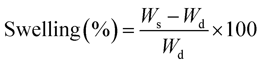
2.8. Swelling response of hydrogels
The swelling behaviour of the hydrogels was investigated by immersing them in phosphate buffered solutions (PBS; pH = 1.0–12.0) at 37 °C till equilibrium. The degree of swelling (%) was calculated according to the following formula:| |
 | (1) |
where Ws and Wd are the weights of the equilibrium swollen and dried hydrogels respectively.
2.9. In vitro drug release studies
The hydrogels have been studied for their drug delivery efficacy for diclofenac sodium (DS), a commonly used non-steroidal anti-inflammatory drug (NSAID), known for its tremendous potential in medicine. Hydrogels (1 mm thick) were dried in vacuo for 24 h to remove any residual moisture. The hydrogels were incubated with 10 mL (1 g mL−1) of DS/ethanol solution for 48 h in the dark. The drug release from the hydrogels was studied in PBS of pH 7.4 and pH 1.2. The release studies were also carried out in simulated gastric (SGF, pH 1.2) and intestinal fluids (SIF, pH 7.4) prepared according to the standard procedure reported in US Pharmacopeia. In vitro drug release was carried out after immersion of the DS-loaded composites into 50 mL PBS (pH 7.4) at 37 °C under constant stirring. 3 mL aliquots were taken out at particular time intervals to determine the drug released from the hydrogels. The withdrawn aliquots were replenished with equal volumes of fresh buffer to simulate physiological conditions. The quantity of DS released was determined spectrophotometrically by monitoring the absorbance at λmax = 276 nm (Cary 100 UV-Vis spectrophotometer, Agilent Technologies) and compared with the standard curve.
2.10. Drug release kinetics
To investigate the preliminary kinetics of drug release from the hydrogels, the release data were fit to four basic kinetic models namely zero order, Higuchi, Ritger–Peppas and Peppas–Sahlin equations. All these models hold good only for the first 60% of drug release.36–39 These equations are given by:| | |
zero order: Mt/M∞ = k0t
| (2) |
| | |
Higuchi: Mt/M∞ = kHt1/2
| (3) |
| | |
Ritger–Peppas: Mt/M∞ = kRPtn
| (4) |
| | |
Peppas–Sahlin: Mt/M∞ = k1tm + k2t2m
| (5) |
Here, Mt/M∞ is the fractional drug release at time t; k0, kH and kRP are the respective kinetic rate constants for the zero order, Higuchi and Ritger–Peppas equations respectively. n is the diffusional exponent indicative of drug transport mechanism and depends on the geometry of the releasing device. For a thin film, when n = 0.5, the drug release mechanism is Fickian diffusion. When n = 1, Case II transport occurs leading to zero-order kinetics. When n lies between 0.5 and 1, anomalous transport is observed.
For Peppas–Sahlin model, the first term of eqn (5) represents the contribution of Fickian diffusion and the second term refers to the macromolecular relaxation contribution on the overall release process. k1 is the diffusion and k2 is the relaxation rate constant. The coefficient m is the Fickian diffusional exponent and its value is 0.5 for thin films. Using the estimated parameters k1 and k2 from eqn (5), the ratio of relaxation (R) and Fickian (F) contributions was calculated using eqn (6) given as:
2.11. Antibiofilm properties
The potential of CMGG/CS hydrogels on biofilm formation was investigated by monitoring the binding of the acridine orange dye to a biofilm forming bacterium of E. coli. 0.5 McFarland suspension of E. coli was prepared from overnight grown culture and inoculated in a 24-well plate containing Luria Bertani broth and supplemented with the hydrogels (5 mm diameter and 1 mm thick). Autoclaved glass slides (1 cm × 1 cm) were partially submerged in the media and incubated at 37 °C for 48 h under static condition. After incubation, the glass slides were washed with PBS followed by staining with 0.01% acridine orange dye solution for 20 minutes. Excess stain was removed with 200 μL PBS and the slides were dried completely. The developed biofilms were monitored under a confocal laser scanning microscope (Carl Zeiss CLSM, Germany). A control set was maintained without any supplementation the hydrogels.
2.12. Hemocompatibility studies
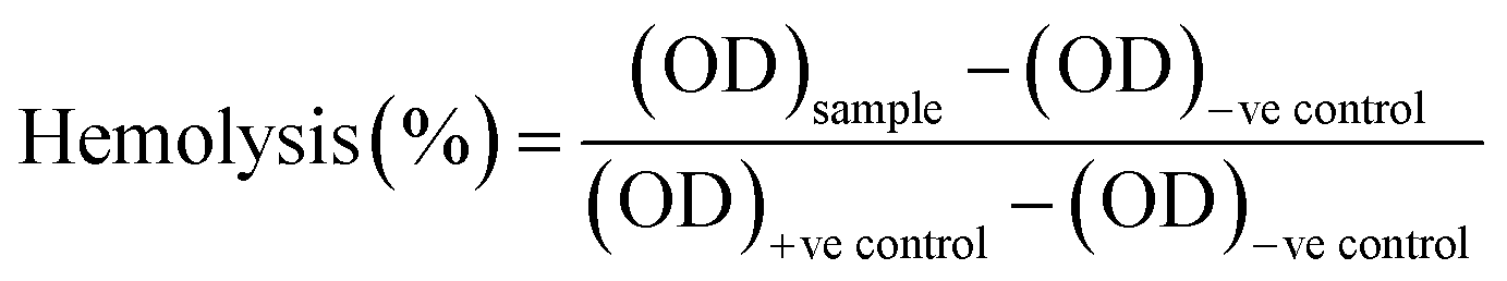
Hemocompatibility assay of the untreated and NTP-modified hydrogels has been performed. All experiments have been conducted in accordance with the Guidelines of Indian Council of Medical Research (ICMR) for biomedical research on human participants. Experiments were approved by the human ethical committee at Ravenshaw University, Cuttack, Odisha, India. An informed consent was obtained from a human volunteer for this study. Fresh venous blood was collected from a healthy human volunteer in heparinized tubes and stored at 4 °C. The hydrogels were incubated with 10 mL of blood for 2 h at 37 °C. Blood incubated with distilled water without test material was considered as the positive control while that with 0.9% normal saline was the negative control. After incubation, the samples were centrifuged for 30 minutes and supernatant was collected with utmost care. The free hemoglobin present in the supernatant was measured spectrophotometrically at λ = 540 nm. The percentage of hemolysis was calculated as:40| |
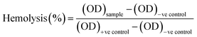 | (7) |
2.13. Biodegradability assay
Biodegradability of the hydrogels was assessed by measuring the weight-loss of the hydrogels (2 cm × 2 cm) buried in soil. Water was sprinkled at regular intervals to prevent the drying of the soil. The samples were periodically removed, washed with water and dried to a constant weight.41
3. Results and discussion
3.1. CMGG synthesis and characterization
The overall reaction for carboxymethylation of GG has been briefly shown in Scheme 1 and the formation of CMGG was affirmed from FTIR, XRD, SEM and 1H NMR analyses.
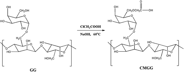 |
| | Scheme 1 Carboxymethylation of guar gum. | |
3.1.1. FTIR analyses. The FTIR spectra of GG and CMGG are represented in Fig. 1A. GG exhibits a broad band around 3377 cm−1 due to O–HStr vibration, 2930 cm−1 due to C–H symmetrical vibration, and the band at 1630 cm−1 is due to scissoring of two O–H bonds of absorbed water molecules.10 However, CMGG shows new absorption bands at 1600 cm−1 and 1420 cm−1 corresponding to COO− asymmetric and symmetric stretching vibrations respectively.10,11 These spectral changes indicated the effectual carboxymethylation of GG.
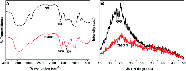 |
| | Fig. 1 (A) FTIR spectra and (B) XRD patterns of GG and CMGG. | |
3.1.2. XRD analyses. The X-ray diffraction patterns of GG and CMGG is shown in Fig. 1B. It was witnessed that native GG exhibited low crystallinity typical of a polymeric material.32 After carboxymethylation, further decrease in crystallinity was observed. This reduction in crystallinity might be attributed to the presence of hydrogen bonds, which might have disrupted the ordered polymer chains of GG and thereby reducing the crystallinity.10,19
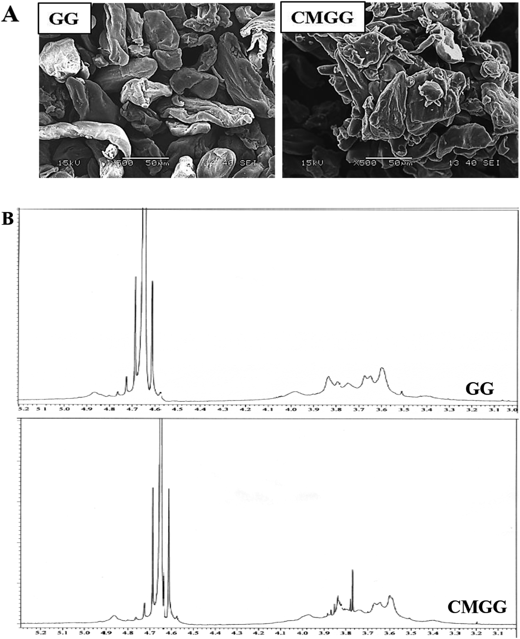
3.1.3. SEM analyses. SEM has been carried out to investigate the granular morphology of native GG and CMGG (Fig. 2A). Pristine GG shows discrete, elongated, irregular structure separated from each other. The morphology of CMGG was significantly altered wherein the granules had adhered to themselves in the form of larger aggregates.
 |
| | Fig. 2 (A) SEM images and (B) 1H NMR spectra of GG and CMGG. | |
3.1.4. 1H NMR analyses. Fig. 2B displays the 1H NMR of GG and CMGG. Native GG exhibits peaks at δ 4.7 and δ 3.5–4.0 ppm associated with anomeric protons and sugar protons respectively.19 The CMGG spectrum revealed the appearance of new proton peaks at δ 3.75, 3.8 and 3.9 ppm ascribed to the methylene protons in the carboxymethyl substituent at the position of C-6 of the α-D-galactose unit and at the position of C-3 of the β-D-mannose unit.11,19 Thus, the proton NMR results confirm the carboxymethylation reaction.
3.2. Characterization of hydrogels
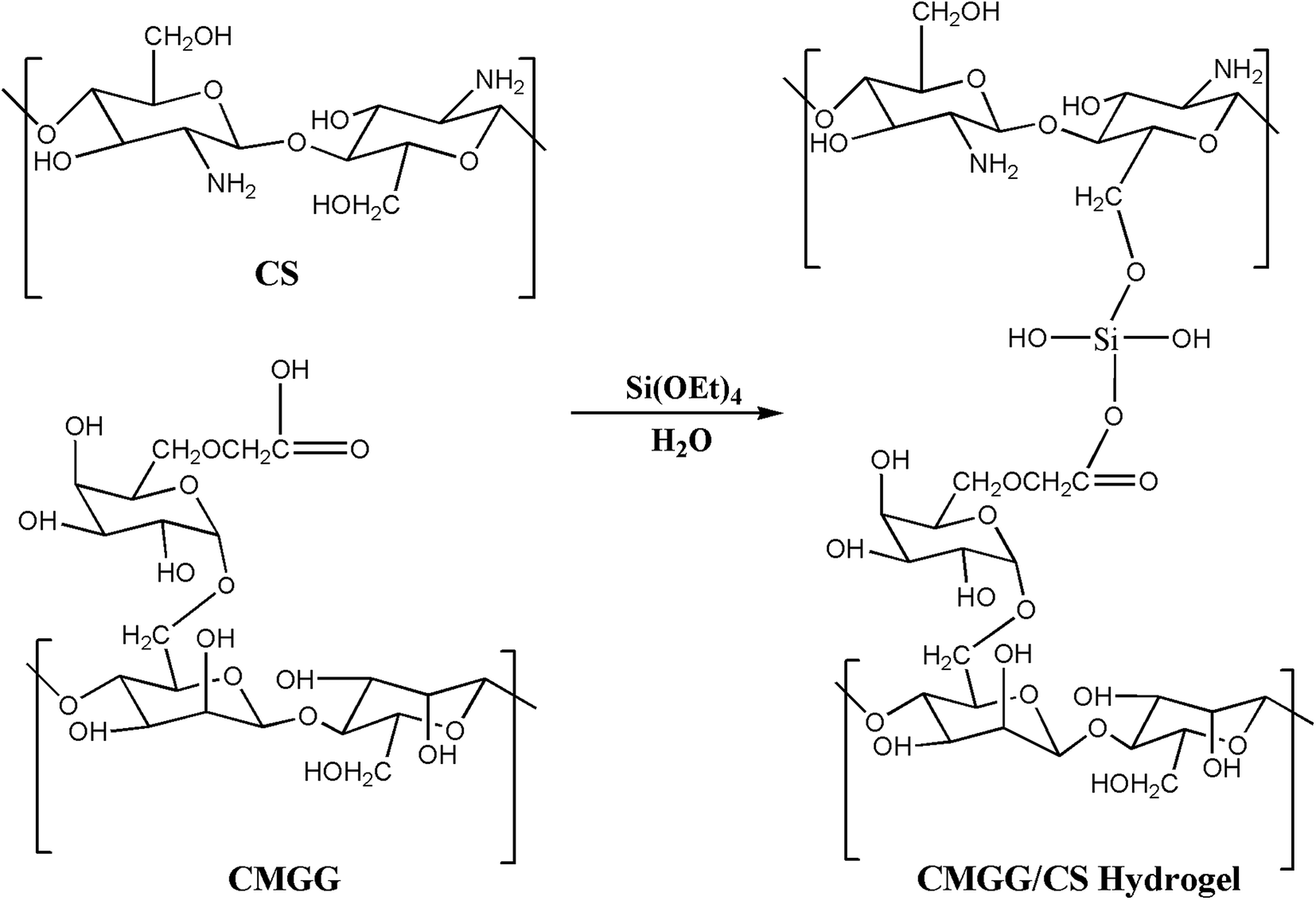
The plausible scheme of mechanism of hydrogel formation between CMGG and CS crosslinked by TEOS is shown in Scheme 2. The synthesized hydrogels have been characterized by FTIR and their surface wettability and topography also inspected.
 |
| | Scheme 2 Schematic of the synthesis of CMGG/CS hydrogel. | |
3.2.1. FTIR analyses. The FTIR elucidations signify the interaction of polymers in a hydrogel and are illustrated in Fig. 3 for the CMGG/CS hydrogels. Pristine CS exhibits key absorption bands at 3440 cm−1 (N–Hstr), 2922 cm−1 (C–Hstr), 1650 cm−1 (NH2 deformation), and 1590 cm−1 (N–Hbend).42 It could be seen that the characteristics bands of CMGG and CS were present in the spectra of the hydrogels with slight shifts from their original positions. The 1420 cm−1 peak arising from COO− symmetric stretching of CMGG was present in the spectra of the hydrogels along with the key peaks of CS. Moreover, a broad band was observed around 1080 cm−1 indicating the presence of siloxane bond (Si–O–) resulting from the crosslinker TEOS.43 The FTIR spectral features of HG@UT were more or less similar to those of plasma-modified hydrogels. However, the plasma-modified hydrogels displayed more significant hydroxyl absorption bands suggestive of their hydrophilic nature acquired post-plasma modification. The HG@Ar + O2 hydrogel demonstrated higher intensity of the hydroxyl absorption band which implied its higher wettability attained post-NTP treatment.
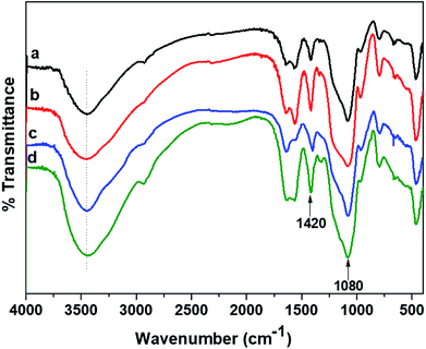 |
| | Fig. 3 FTIR spectra of (a) HG@UT, (b) HG@Ar, (c) HG@O2 and (d) HG@Ar + O2. | |
3.2.2. Surface wettability studies. CA measurement is one of the direct methods to investigate the hydrophilic/hydrophobic nature of materials acquired post-plasma treatment. The results for the water drop equilibrium CA measurement have been shown in Fig. 4. As clearly witnessed from the photographs, the water CA of the hydrogels decreased substantially following plasma modification.
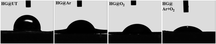 |
| | Fig. 4 Digital photographs of water droplets on the hydrogel surfaces. | |
The influence of plasma-modifications on the CA and SFE values of CMGG/CS hydrogels are listed in Table 1.
Table 1 CA and SFE of hydrogels treated with various gaseous plasmas
| Parameters |
Hydrogels |
| HG@UT |
HG@Ar |
HG@O2 |
HG@Ar + O2 |
| Contact angle (°) |
| Water |
60.32 ± 0.02 |
40.22 ± 0.59 |
30.90 ± 0.23 |
18.58 ± 0.91 |
| Ethylene glycol |
30.50 ± 1.45 |
21.53 ± 0.97 |
19.56 ± 0.87 |
17.01 ± 1.76 |
|
| Surface free energy (mJ m−2) |
| Dispersive (γd) |
20.43 ± 1.10 |
7.94 ± 0.46 |
4.44 ± 0.26 |
2.09 ± 0.27 |
| Polar (γp) |
21.77 ± 0.74 |
51.08 ± 1.16 |
65.50 ± 0.61 |
80.75 ± 1.37 |
| Total (γtotal) |
42.20 ± 0.36 |
59.02 ± 0.73 |
69.94 ± 0.36 |
82.84 ± 1.12 |
A significant reduction in the CA values was witnessed for all the plasma-treated specimens in comparison to the untreated hydrogel. This indicated that the wettability was greatly enhanced post-plasma modification. For the plasma-modified hydrogels, the lowering in CA values could be ascribed to the addition of new polar groups on the hydrogel surfaces (γp evident from Table 1). The hydrophilicity of the hydrogels was found to increase in the order of HG@UT < HG@Ar < HG@O2 < HG@Ar + O2. This observation could be rationalized by considering the nature of etching induced upon the hydrogel surface by the plasma-generating gases. While Ar plasma has been known to induce physical etching; O2 plasma generally stimulate chemical etching.33 Conversely, the mixture of Ar and O2 plasmas further enhances the hydrophilicity probably owing to the coupled effects of physical and chemical etching on the hydrogel surface.33
The energy of the surface (SFE), which is directly related to its wettability, is an important criterion that has often been strongly correlated with the cell–biomaterial interfacial interactions. The higher the SFE and the smaller the CA; the stronger is the adhesion between the two surfaces. It was witnessed that HG@UT presented a lower SFE value of 42.20 whereas the energies increased to 59.02, 69.94 and 82.84 mJ m−2 for HG@Ar, HG@O2 and HG@Ar + O2 respectively. The HG@Ar + O2 was found to be the most hydrophilic of the lot with lowest CA and highest SFE characteristics likely attributed to the combined influences of Ar and O2 plasmas on its surface.
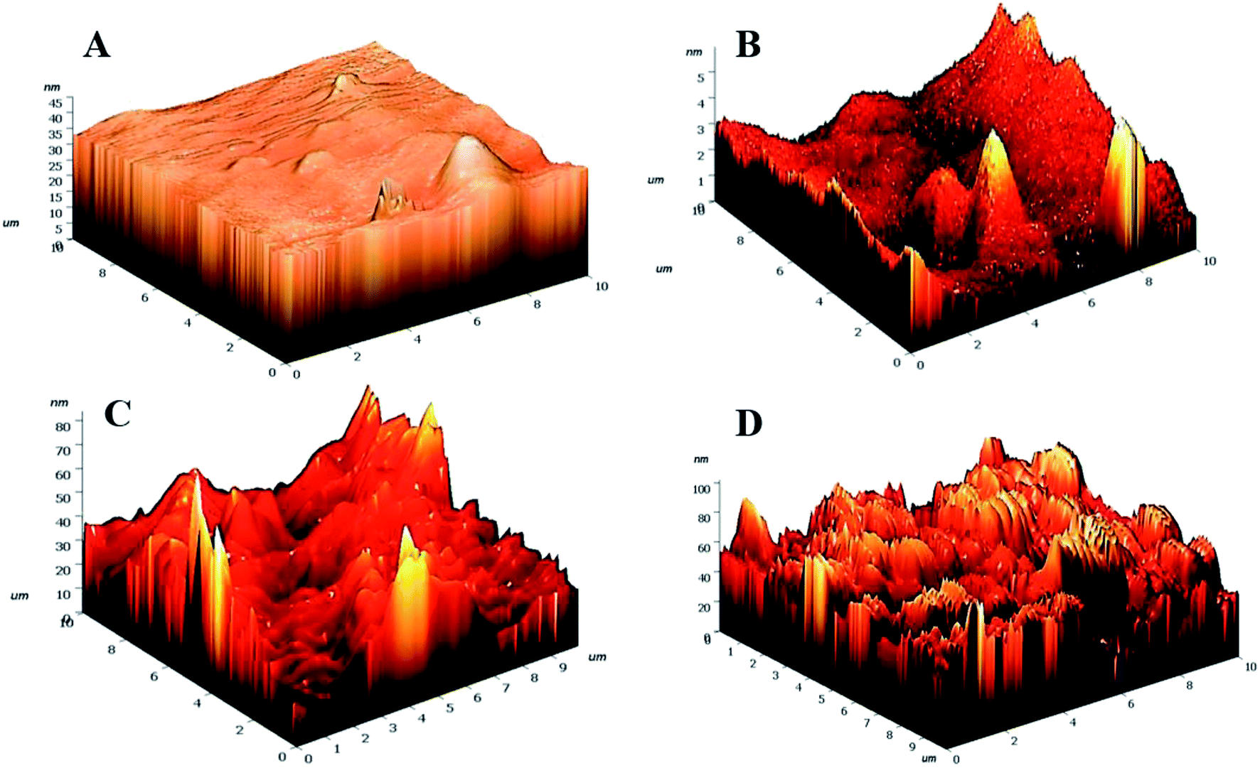
3.2.3. Surface topographical analyses. Etching processes are inevitable owing to the bombardment of plasma particles on the hydrogel surfaces. To explore the extent of etching incurred by the hydrogels post-plasma treatment, AFM have been employed (Fig. 5).
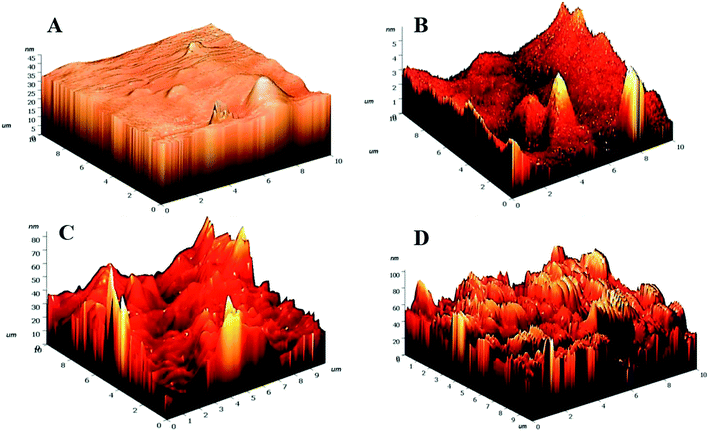 |
| | Fig. 5 3D AFM images of (A) HG@UT, (B) HG@Ar, (C) HG@O2 and (D) HG@Ar + O2. | |
Drastic transformation in the topography of the hydrogels post-NTP modification was visualized. The HG@UT appeared to be smooth and even. In stark contrast, the plasma-modified hydrogels revealed to be pretty much uneven, irregular and coarse. The roughness parameters have been quantified in terms of root mean squared (rms) values. Lower rms values are suggestive of a smoother surface. The rms values were estimated to be 1.59 ± 1.50, 8.07 ± 1.33, 9.00 ± 1.45 and 13.44 ± 2.12 nm respectively for HG@UT, HG@Ar, HG@O2 and HG@Ar + O2 hydrogels respectively. The degree of surface roughness induced by Ar + O2 plasma on the hydrogel was much higher than that induced by Ar and/or O2 alone. This could be accounted for the coupled effects of the reactive Ar + O2 plasmas impinging on hydrogel surface that lead to higher etching. It was obvious from the AFM studies that NTP treatment induced topographical changes of the hydrogels at the nano-scale level without any adverse effect on their bulk physical structure.
3.3. pH-responsive swelling of hydrogels. Role of pH is vital in biomedical and pharmaceutics. In this study, the swelling response of the hydrogels was investigated at different pHs. The influence of pH on the swelling of the hydrogels is shown in Fig. 6.
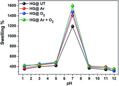 |
| | Fig. 6 pH dependent swelling of hydrogels in buffer at 37 °C. | |
The hydrogels exhibited pH-sensitive swelling with maximum swelling at neutral pH and lower swelling at acidic and basic pH. Due to protonation of amino groups in CS at lower pH, strong electrostatic repulsion occurs between the polymer chains. As a result, the flow of counter ions into the hydrogel matrix takes place and the overall electrostatic potential is neutral. Thus, the increased osmotic pressure inside the hydrogel results in a reduced water uptake capacity. At neutral pH, the deprotonation of –NH3+ occurs and intrachain hydrogen bonding take places in the matrix, increasing the water uptake capacity and subsequently, the swelling. At basic pH, due to complete deprotonation of –NH3+ groups, the degree of ionization of the hydrogels is lowered and there is a possibility of extensive hydrogen bonding in the hydrogel matrix, resulting in a more compact structure and swelling is thus lowered.42,43 The swellability was found to be of the order HG@UT < HG@Ar < HG@O2 < HG@Ar + O2. The higher water uptake capacity of HG@Ar + O2 could be linked to its higher hydrophilicity ensuing from plasma treatment.
3.4. Morphological analyses of hydrogels
To have an idea about the morphology, the equilibrium swollen hydrogels (in pH 7.4) were frozen at −20 °C for 5 h, lyophilized at −55 °C for 24 h and then observed under SEM (Fig. 7).
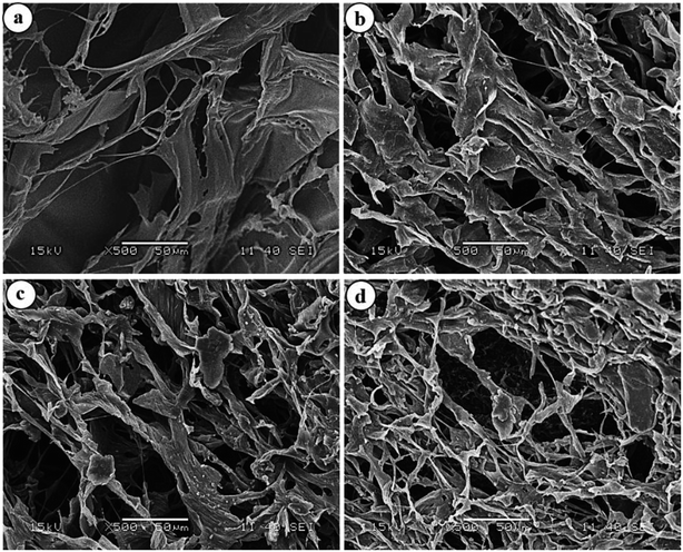 |
| | Fig. 7 SEM images of (a) HG@UT, (b) HG@Ar, (c) HG@O2 and (d) HG@Ar + O2. | |
The images revealed a continuous macroporous network structure of the hydrogel matrices. While the plasma-treated hydrogels disclosed a much porous morphology, the HG@UT appeared relatively less porous and compact. This observation could be justified by considering the higher water uptake capacity of the hydrogels post-plasma modification that renders the matrix a porous morphology. Hydrogels possessing such morphology are particularly suited as antibacterial/wound-healing materials.
3.5. Drug delivery and kinetics
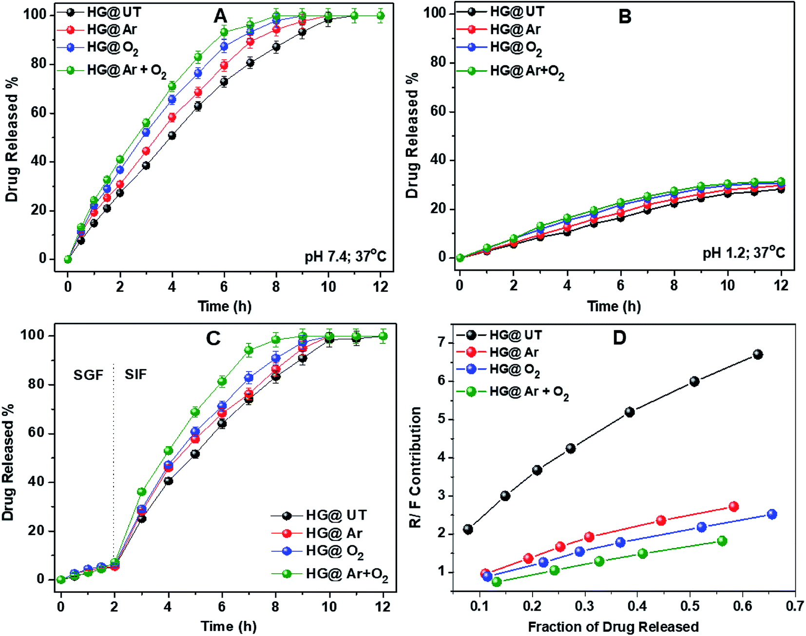
3.5.1. DS release studies from CMGG/CS hydrogels. DS release profiles of the hydrogels in pH 7.4 and 1.2 at 37 °C have been illustrated in Fig. 8A and B. As evident, a pronounced difference was observed in the release rates of DS at the two pHs. The amounts of DS released from all the hydrogels at pH 1.2 was always much lower than that at pH 7.4, even upon prolonged exposure to the releasing medium. This observation could be attributed to the difference in the extent of swelling of these hydrogels in the above two pH conditions.
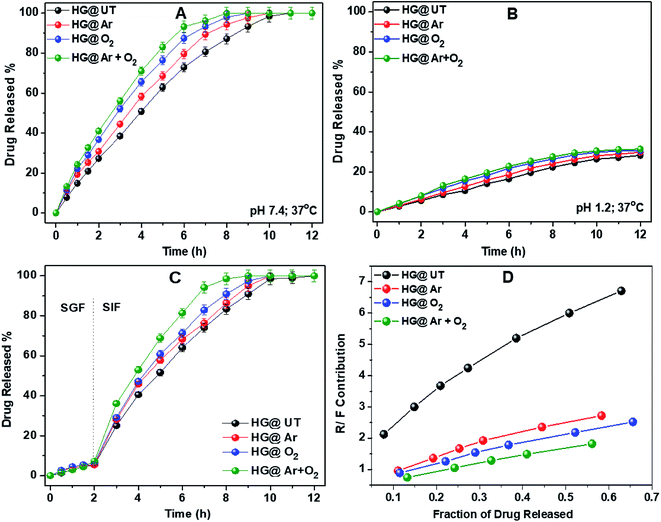 |
| | Fig. 8 Drug release profiles of hydrogels in (A) pH 7.4, (B) pH 1.2, (C) SGF, SIF at 37 °C and (D) plot of R/F vs. fraction of drug released from hydrogels. | |
To further emulate the conditions of the gastrointestinal tract, DS release from the hydrogels was studied in SGF and SIF. The hydrogels were immersed in SGF for 2 h, then transferred to SIF and the drug release was monitored. Fig. 8C depicts the DS release profile in SGF and SIF environments. Approximately 10% of DS was released during the initial 2 h in SGF. However, the rate of DS release was increased significantly when the hydrogels were transferred to SIF. This release profile of DS fulfils the requirements of US Pharmacopeia for oral drug delivery to the lower part of the gastrointestinal tract targeting the colon.43
3.5.2. DS release kinetics. Table 2 summarizes the kinetic parameters for DS release data which provides an approximate idea about the drug transport mechanism from the hydrogels.
Table 2 Kinetic and fitting parameters for drug release data fit to various equations
| Hydrogels |
Models |
| Higuchi |
Ritger–Peppas |
Peppas–Sahlin |
Zero-order |
| kH |
R2 |
n |
kRP |
R2 |
k1 |
k2 |
R2 |
k0 |
R2 |
| HG@UT |
0.231 |
0.842 |
0.91 |
0.144 |
0.999 |
0.037 |
0.108 |
0.999 |
0.128 |
0.994 |
| HG@Ar |
0.246 |
0.870 |
0.82 |
0.181 |
0.996 |
0.077 |
0.105 |
0.997 |
0.151 |
0.971 |
| HG@O2 |
0.282 |
0.876 |
0.81 |
0.211 |
0.999 |
0.093 |
0.118 |
0.998 |
0.173 |
0.970 |
| HG@Ar + O2 |
0.286 |
0.878 |
0.78 |
0.237 |
0.999 |
0.115 |
0.121 |
0.998 |
0.200 |
0.951 |
From Table 2, it was observed that DS release data showed the best fit to the Ritger–Peppas and Peppas–Sahlin models for all the hydrogels. The value of the diffusion coefficient n lied between 0.78 and 0.91 indicating the anomalous nature of drug release, where both diffusion and relaxation processes contribute. To know exactly the contribution of both these processes, the ratio of the relaxational over Fickian contributions (R/F) was calculated using the estimated values of k1 and k2 and plotted against the fraction of DS released from these hydrogels (Fig. 8D). The predominant influence of macromolecular chain relaxation on the drug release was observed for HG@UT. However, ensuing plasma-modification, the drug release mechanism was mostly diffusion-controlled. The lowest R/F values of HG@Ar + O2 were suggestive of the prevalence of diffusion process over the relaxation process that drive the drug delivery phenomenon.
3.6. In vitro antibiofilm propensity
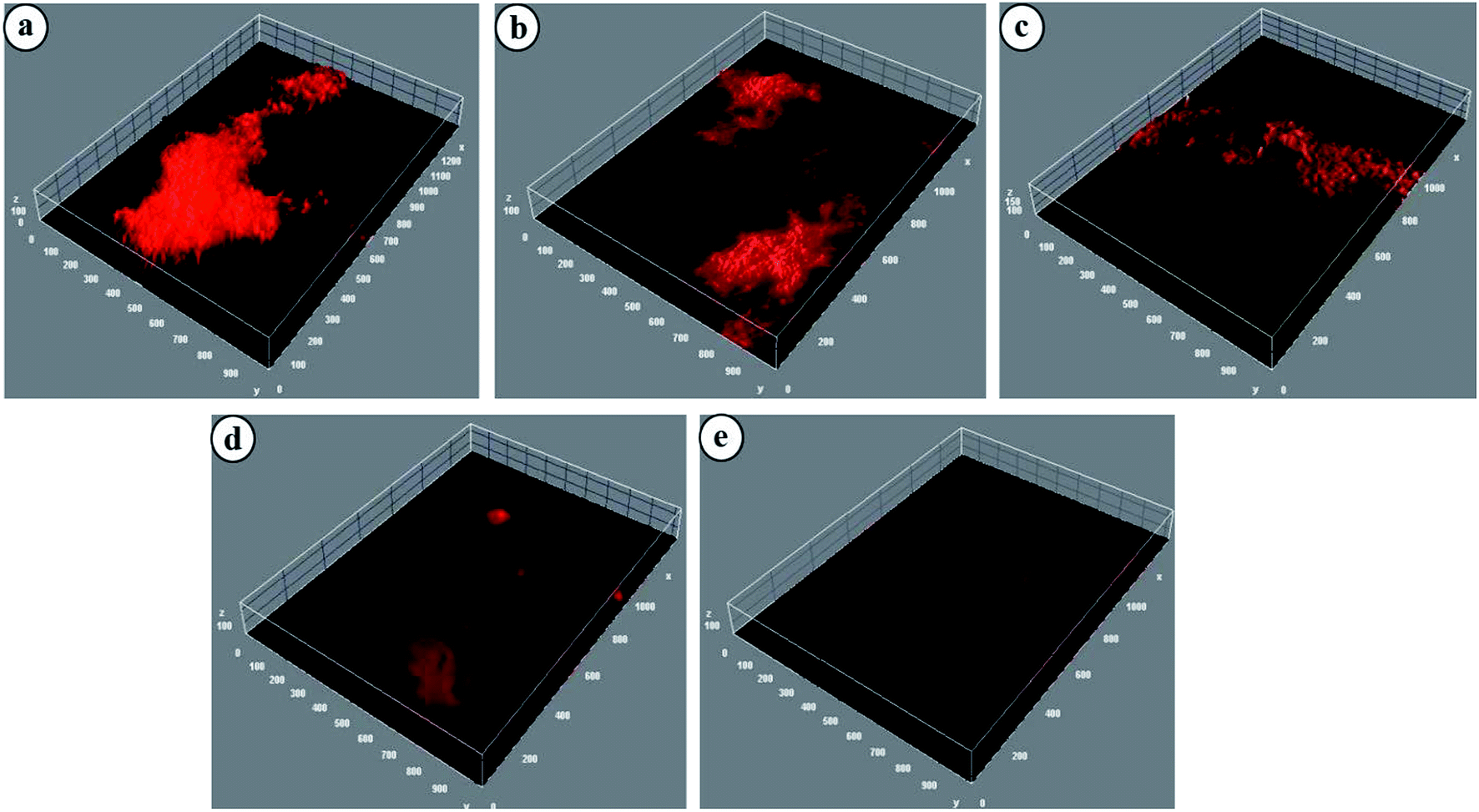
Biofilms are defined as three-dimensional structures formed by assemblages of microorganisms attached to a surface and their associated extracellular products.44 Biofilms particularly formed by pathogenic bacteria are responsible for biomaterial-related infections, nonhealing chronic wounds, dental diseases, endocarditis, etc. The detrimental effect of biofilms on wound healing makes mechanical removal of debris and biofilms critical in chronic wound therapy. NTP, as a potential strategy against biofilm eradication, is well-established.44 Most of the relevant studies have been carried out by directly exposing the bacterial medium to the plasma sources. However, the potential of NTP treated hydrogels for eradication of biofilms has, to date, received no attention. In this study, NTP modified CMGG/CS hydrogels have been explored for their biofilm eradication efficacy against E. coli and the images have been displayed in Fig. 9.
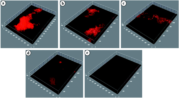 |
| | Fig. 9 Confocal images of E. coli treated with (a) Control, (b) HG@UT, (c) HG@Ar, (d) HG@O2 and (e) HG@Ar + O2. | |
For HG@UT, the bacterium is seen to form large aggregates which is clearly visible in the biofilm generation. However, following plasma-modification, there was a visible reduction in the extent of bacterial aggregation and the biofilms appeared more diffused. The HG@O2 and HG@Ar + O2 hydrogels displayed better biofilm eradication characteristics in comparison to HG@UT. The above results signified the good antibiofilm efficacy of the hydrogels post NTP treatment. Further investigation and tailored development of NTP-modified hydrogels could provide a new direction towards antibiofilm and subsequently, anti-biofouling prevention.
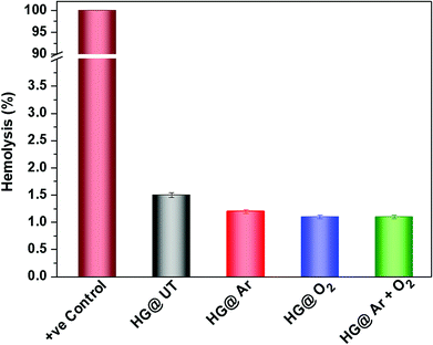
3.7. Hemocompatibility assessment
It is of utmost importance to assess a biomaterial in terms of its hemocompatibility. The hydrogels were incubated with human blood and the results have been depicted in Fig. 10. As evident, hemolysis was found to be around 1.5% for the NTP-modified hydrogels; which is quite below the permissible limit (upto 5%) for biomaterials.45 Thus, NTP-treatment did not evoke any detrimental effect with human blood. Therefore, these hydrogels meet the hemocompatibility criteria and can be efficaciously utilized in biomaterial formulations.
 |
| | Fig. 10 Hemolysis (%) of human RBCs after incubation with CMGG/CS hydrogels. | |
3.8. Biodegradability
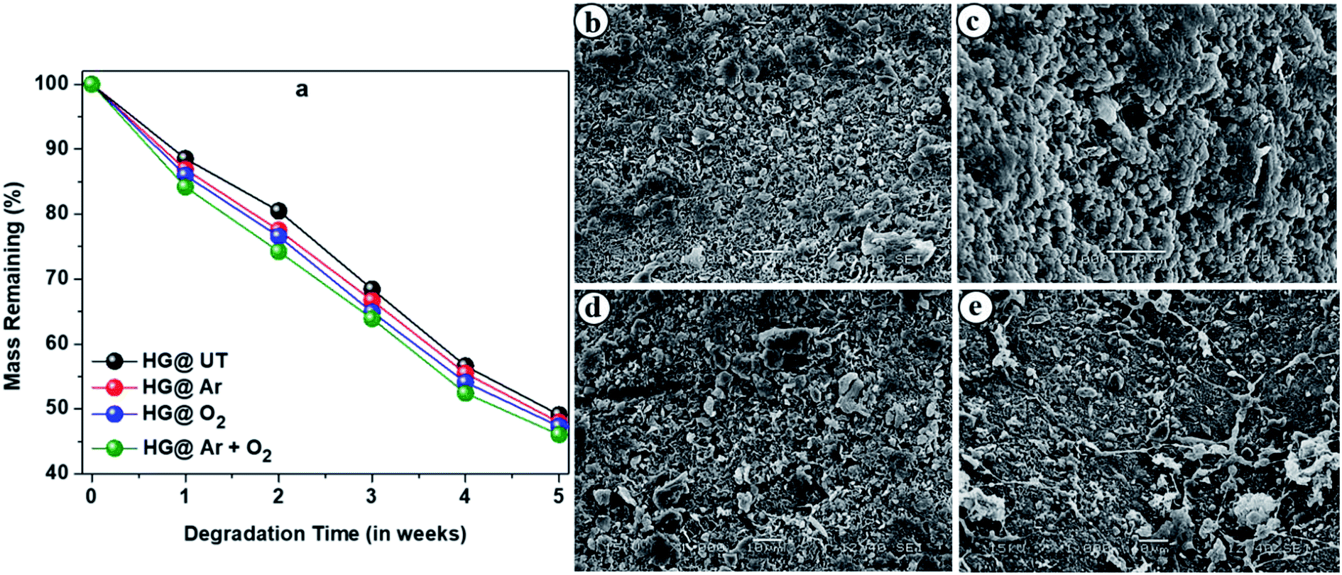
Biodegradability is a crucial criterion to be considered while fabrication of materials intended for pharmaceutical formulations. Microorganisms and fungi present in the soil are mainly responsible for degradation of these hydrogels. The degradation profiles of the hydrogels are shown in Fig. 11a which revealed them to be highly biodegradable.
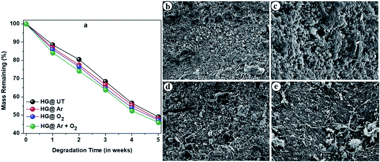 |
| | Fig. 11 (a) Degradation profiles of the hydrogels upon burying in soil. SEM images of the biodegraded hydrogels; (b) HG@UT, (c) HG@Ar, (d) HG@O2 and (e) HG@Ar + O2. | |
Fig. 11b–e presents the SEM images of biodegraded HG@UT, HG@Ar, HG@O2 and HG@Ar + O2 hydrogels. As evident, the morphology clearly indicated the degradation and erosion of the samples. Thus, apart from being excellent biodegradable materials, the CMGG/CS hydrogels can be potentially explored for their diverse applications in biomedicine.
4. Conclusion
CMGG/CS hydrogels have been fabricated using a green crosslinker TEOS. To render the hydrogels a higher degree of biological efficacy; NTP assisted surface modification have been performed using Ar, O2 and a mixture of Ar and O2 gaseous plasmas. Higher hydrophilicity and surface energy ensuing from the plasma treatment were witnessed from CA and SFE studies. The AFM analyses revealed that plasma treatment induced topographical changes at the nano-scale level without any adverse effect on the bulk physical structure. The HG@Ar + O2 exhibited higher degree of roughness attributed to the coupled effects of the reactive Ar + O2 plasmas impinging on its surface. The NTP-modified hydrogels possessed a highly porous network structure and could be utilized as wound-healing agents. The hydrogels exhibited pH-responsive swelling with maximum swelling in neutral pH. DS release from the hydrogels in SGF and SIF environments confirmed that they could be employed for colon-targeted drug delivery. The preliminary drug release kinetics revealed that drug release from NTP-modified hydrogels was predominantly diffusion-controlled. Excellent biofilm eradication features against E. coli was demonstrated by the hydrogels. Hemolytic experiments on human RBCs confirmed their hemocompatibility. The hydrogels were also found to be remarkably biodegradable. Thus, NTP-assisted surface nano-textured CMGG/CS hydrogels are truly potent for myriad biomedical applications.
Conflicts of interest
The authors declare no conflicts of interest.
References
- A. S. Hoffman, Adv. Drug Delivery Rev., 2012, 54, 18–23 CrossRef.
- N. A. Peppas, P. Bures, W. Leobandung and H. Ichikawa, Eur. J. Pharm. Biopharm., 2000, 50, 27–46 CrossRef CAS PubMed.
- A. Vashist, A. Vashist, Y. K. Gupta and S. Ahmad, J. Mater. Chem. B, 2014, 2, 147–166 RSC.
- T. R. Hoare and D. S. Kohane, Polymer, 2008, 49, 1993–2007 CrossRef CAS.
- L. Gao, J. Fei, J. Zhao, W. Cui, Y. Cui and J. Li, Chem.–Eur. J., 2012, 18, 3185–3192 CrossRef CAS PubMed.
- M. Prabaharan, Int. J. Biol. Macromol., 2011, 49, 117–124 CrossRef CAS PubMed.
- N. Thombare, U. Jha, S. Mishra and M. Z. Siddiqui, Int. J. Biol. Macromol., 2016, 88, 361–372 CrossRef CAS PubMed.
- T. M. Aminabhavi, M. N. Nadagouda, S. D. Joshi and U. A. More, Expert Opin. Drug Delivery, 2014, 11, 753–766 CrossRef CAS PubMed.
- G. Sharma, S. Sharma, A. Kumar, A. H. Al-Muhtaseb, M. Naushad, A. A. Ghfar, G. T. Mola and F. J. Stadler, Carbohydr. Polym., 2018, 199, 534–545 CrossRef CAS PubMed.
- H. Gong, M. Liu, J. Chen, F. Han, C. Gao and B. Zhang, Carbohydr. Polym., 2012, 88, 1015–1022 CrossRef CAS.
- G. Dodi, A. Pala, E. Barbu, D. Peptanariu, D. Hritcu, M. I. Popa and B. I. Tamba, Mater. Sci. Eng., C, 2016, 63, 628–636 CrossRef CAS PubMed.
- S. Pal, J. Appl. Polym. Sci., 2009, 111, 2630–2636 CrossRef CAS.
- M. S. Narasimha, S. R. Hiremath and K. L. Paranjothy, Int. J. Pharm., 2004, 272, 11–18 CrossRef PubMed.
- G. Dodi, D. Hritcu and M. I. Popa, Cellul. Chem. Technol., 2011, 45, 171–176 CAS.
- S. Parveen, M. Ranjita and S. K. Sahoo, Nanomedicine, 2012, 8, 147–166 CrossRef CAS PubMed.
- A. Kumari, S. K. Yadav and S. C. Yadav, Colloids Surf., B, 2010, 75, 1–18 CrossRef CAS PubMed.
- R. T. Thimma and S. Tammishetti, J. Appl. Polym. Sci., 2001, 82, 3084–3090 CrossRef CAS.
- A. G. Sullad, L. S. Manjeshwar and T. M. Aminabhavi, J. Appl. Polym. Sci., 2011, 122, 452–460 CrossRef CAS.
- P. J. Manna, T. Mitra, N. Pramanik, V. Kavitha, A. Gnanamani and P. P. Kundu, Int. J. Biol. Macromol., 2015, 75, 437–446 CrossRef CAS PubMed.
- S. Kundu, A. Das, A. Basu, D. Ghosh, P. Datta and A. Mukherjee, Carbohydr. Polym., 2018, 191, 71–78 CrossRef CAS PubMed.
- N. R. Gupta, A. T. A. Torris, P. P. Wadgaonkar, P. R. Rajamohanan, G. Ducouret, D. Hourdet, C. Creton and M. V. Badiger, Carbohydr. Polym., 2015, 117, 331–338 CrossRef CAS PubMed.
- K. V. Phadke, L. S. Manjeshwar and T. M. Aminabhavi, Polym. Bull., 2014, 71, 1625–1643 CrossRef CAS.
- M. Rinaudo, Prog. Polym. Sci., 2006, 31, 603–632 CrossRef CAS.
- M. Dash, F. Chiellini, R. M. Ottenbrite and E. Chiellini, Prog. Polym. Sci., 2011, 36, 981–1014 CrossRef CAS.
- N. Bhattarai, J. Gunn and M. Zhang, Adv. Drug Delivery Rev., 2010, 62, 83–99 CrossRef CAS PubMed.
- H. Hamedi, S. Moradi, S. M. Hudson and A. E. Tonelli, Carbohydr. Polym., 2018, 199, 445–460 CrossRef CAS PubMed.
- M. C. G. Pella, M. K. Lima-Tenorio, E. T. Tenorio-Neto, M. R. Guilherme, E. C. Muniz and A. F. Rubira, Carbohydr. Polym., 2018, 196, 233–245 CrossRef CAS PubMed.
- A. M. G. Borges, L. O. Benetoli, M. A. Licinio, V. C. Zoldan, M. C. Santos-Silva, J. Assreuy, A. A. Pasa, N. A. Debacher and V. Soldi, Mater. Sci. Eng., C, 2013, 33, 1315–1324 CrossRef CAS PubMed.
- A. Shekaran and A. J. Garcia, Biochim. Biophys. Acta, 2011, 1810, 350–360 CrossRef CAS PubMed.
- S. E. Woodcock, W. C. Johnson and Z. Chen, J. Colloid Interface Sci., 2005, 292, 99–107 CrossRef CAS PubMed.
- T. Desmet, R. Morent, N. De Geyter, C. Leys, E. Schacht and P. Dubruel, Biomacromolecules, 2009, 10, 2351–2378 CrossRef CAS PubMed.
- G. Fridman, G. Friedman, A. Gutsol, A. B. Shekhter, V. N. Vasilets and A. Fridman, Plasma Processes Polym., 2008, 5, 503–533 CrossRef CAS.
- M. C. Ramkumar, K. N. Pandiyaraj, A. Arunkumar, P. V. A. Padmanabhan, S. Udaykumar, P. Gopinath, A. Bendavid, P. Cools, N. De Geyter, R. Morent and R. R. Deshmukh, Appl. Surf. Sci., 2018, 439, 991–998 CrossRef CAS.
- E. Njatawidjaja, M. Kodama, K. Matsuzaki, K. Yasuda and T. Matsuda, Plasma Processes Polym., 2006, 3, 338–341 CrossRef CAS.
- P. L. R. Cunha, R. C. M. de Paula and J. P. A. Feitosa, Int. J. Biol. Macromol., 2007, 41, 324–331 CrossRef CAS PubMed.
- L. Serra, J. Domenech and N. A. Peppas, Biomaterials, 2006, 27, 5440–5451 CrossRef CAS PubMed.
- T. Higuchi, J. Pharm. Sci., 1963, 52, 1145–1149 CrossRef CAS PubMed.
- P. L. Ritger and N. A. Peppas, J. Controlled Release, 1987, 5, 37–42 CrossRef CAS.
- N. A. Peppas and J. J. Sahlin, Int. J. Pharm., 1989, 57, 169–172 CrossRef CAS.
- P. Das, N. Ojah, R. Kandimalla, K. Mohan, D. Gogoi, S. K. Dolui and A. J. Choudhury, Int. J. Biol. Macromol., 2018, 114, 1026–1032 CrossRef CAS PubMed.
- H. L. A. El-Mohdy and S. Ghanem, J. Polym. Res., 2009, 16, 1–10 CrossRef.
- S. Das and U. Subuddhi, Ind. Eng. Chem. Res., 2013, 52, 14192–14200 CrossRef CAS.
- A. Islam and T. Yasin, Carbohydr. Polym., 2012, 88, 1055–1060 CrossRef CAS.
- S. A. Ermolaeva, E. V. Sysolyatina and A. L. Gintsburg, Biointerphases, 2015, 10, 029404 CrossRef PubMed.
- N. S. Rejinolda, A. Naira, M. Sabithaa, K. P. Chennazhia, H. Tamura, S. V. Naira and R. Jayakumar, Carbohydr. Polym., 2012, 87, 943–949 CrossRef.
|
| This journal is © The Royal Society of Chemistry 2019 |
Click here to see how this site uses Cookies. View our privacy policy here. 
 Open Access Article
 This Open Access Article is licensed under a Creative Commons Attribution-Non Commercial 3.0 Unported Licence
 *
*